Aqua Lights AL250MH Instruction Manual
AL250MH
Underwater Hull Light
Installation and Maintenance
Instructions Manual

This underwater light has been carefully designed to pro ide a ersatile product of the highest quality, suitable for a wide range of
underwater applications such as marine, industrial and domestic.
WARNING! Sections in this manual identify safe practice. It is of the utmost importance that this manual is carefully read and
understood. Failure to do so may result in electric shock, injury, fire, or equipment damage. PLEASE READ CAREFULLY and, if in
doubt, seek professional ad ice.
Features
• Light source: 250-watt Metal Halide bulb with 4600° K Reflector
• Lamp replacement: The unit features rear access allowing simple replacement of lamps without remo ing the fitting
• Thermal management: The housing has been carefully designed with internal air gap and special enting/con ection to direct
heat away from that part of the housing in contact with the boat hull or other mounting surface. The housing locking ring has also
been designed as a heat sink to further dissipate heat effecti ely away from where it is not wanted.
• Lamp housing: The lamp housing is manufactured from na al bronze machined to the highest standards.
• Seals: All the seals are made from high temperature silicone rubber for reliability.
• Lens: Our lens is made from BoroTrans
sm
for high temperatures and harsh en ironments.
• Installation: The fixture is supplied with user friendly fixing hardware pro ided. There is a le eling ring supplied to allow fitment
where the inner surface may not be parallel to the outside surface.
Specifications (Fixture & Lamp Assembly)
• Body: Na al Bronze
•
Lens Bezel:
Na al Bronze

• Lens: 1/2" BoroTrans
sm
• Seals and Gaskets: High temperature (200° C) silicone rubber
• Lamp Cable: High Temperature (200° C) silicone rubber insulated
• Fixture Weight: 27 Lbs
• Cutout Size: 6” (110 mm)
• Maximum ull Thickness: 6" (125 mm)
• Minimum ull Thickness: 0.25” (6 mm)
• Water Ingress Protection Rating: IP66
Specifications ELECTRICAL
• Mains input voltage: 120Vac 60Hz (240Vac 50Hz a ailable on request)
• Mains current draw: 1.75 amps
• Power factor: 90%
• Lamp output starting (ignition) voltage: 4K
• Lamp running voltage: approx 88V
• Ballast housing: UL-appro ed cast aluminum (epoxy coated)
• Size: 12” x 6” x 7”
• Weight: 19.5 Lbs
• Rating: IP56
• Labeling: Operation and Warning label fitted to outside of co er with wiring diagram fitted to inside of co er.
• Cable entries: Glanded
Operation and Maintenance
• WARNING: Ne er operate the light out of water as the water pro ides necessary cooling. The lens bezel must be completely
submerged at all times. A oid operating the light when the boat is planning as often times this raises the fixture bezel abo e the
water-line and thus diminishing the cooling effect of the water. Generally, Halogen lamps ha e a ser ice life of approximately
2,000 hours. This may ary depending on the number of restarts and other factors.
Replacing the Lamp
• Isolate mains power and assure it can not be re energized accidentally by other persons.
•
Allow the lamp and housing to cool down (minimum 20 minutes). Check carefully that the unit has cooled sufficiently before

attempting to open the housing.
• Using your hand, loosen the rear lock ring, (turning counter clockwise).
• Once the ring is free, carefully withdraw the lamp assembly from the housing.
• NOTE: Ensure the area local to the light is relati ely dry, thus ensuring bilge water can not enter
the opened housing. Also ensure
the withdrawn lamp assembly DOES NOT comes in contact with water at any time. It MUST remain clean and dry at all times. Should
the assembly come in contact with water, contact your nearest supplier for further ad ice. Do not re-assemble and re-energize.
• Hold the cable end of the lamp assembly and rotate (counter clockwise) the reflector case. Unscrew until the lamp is exposed.
•
Carefully withdraw the spent lamp from its socket. It is recommended to use a glo e or thick cloth as the lamp may shatter causing
injury.
•
Inspect the lamp socket carefully for any signs of damage or corrosion. Basic cleaning may be carried out using dried, compressed
air. DO NOT spray contact cleaner into any part of the lamp holder assembly.
• Carefully remo e new lamp from its packing. Using a clean cloth, fit the new lamp into the 4 Socket. IMPORTANT! Ensure the new
lamp is wiped totally clean of any dirt or fingerprints. Failure to do so will result in premature lamp burn-out.
•
Inspect the housing to ensure it is completely clean and dry. The lens may be cleaned if necessary using a soft cloth on the end of a
wooden dowel or similar. Re inspect after cleaning to ensure no cloth or other cleaning fibers remain inside the housing. NEVER!
Spray lubricants, degreasing agents or other similar products into the housing. Carefully re-
fit the lamp assembly into the housing
ensuring the front end of the reflector case locates correctly into the front end of the lamp housing. This can be felt by mo ing the
assembly around until it drops neatly into position with the rear end cap snug against the silicone seal.
• Re-
fit the outer lock ring. Again it is recommended to apply a thin layer of silicone based grease to the thread and surface in
contact with the end cap.
• NOTE: at no point is it necessary to loosen the cable gland nut; howe er it should be checked to insure it is secure and snug around
cable, DO not pull excessi ely on the cable.
Other Maintenance
• Check to ensure the underwater lens is clean and free of marine growth. It may be cleaned using a nylon brush or plastic
scraper.
• Replacement parts and accessories: A full range of Replacement parts and accessories are a ailable. Please contact your
supplier for any requirements.
• Should there be a malfunction for any reason, please consult your nearest agent or Aqua Lights directly. The housing should not
be opened under any circumstances unless by a suitably qualified and authorized technician.
Safety and General Information

T E FOLLOWING INFORMATION IS IMPORTANT TO T E SAFE OPERATION OF T IS EQUIPMENT, ACCORDINGLY MUST BE
OBSERVED AND ACTIONED AS NECESSARY.
• This Light should only be installed by suitably trained trades persons experienced in the fitting of through hull equipment and
marine Mains Voltage AC electrical systems.
• It is important that the housing is electrically bonded to the essels cathodic protection grounding system. Failure to solidly
ground will result in corrosion, leading to serious damage or loss of essel, property and life. Regular checks/testing must be
carried out to ensure the metal housing is electrically bonded to the essels cathodic protection grid.
• If the housing shows signs of excessi e corrosion (other than surface contamination) or physical damage, the essel should be
hauled so a complete assessment can be performed. Any signs of water ingress must be addressed immediately.
• As this equipment operates on mains oltages, it is of the utmost importance that all equipment is maintained in first rate
working order at all times. Regular inspections should be carried out to ensure all wiring is in good condition, clear of wet areas
and not exposed to mechanical interference.
• Any suspect equipment must be repaired or replace.
• The Lens and Bezel ha e been carefully designed with a smooth, flush surface to allow easy cleaning.
• Ne er operate the essel with the lamp housing end cap remo ed.
Limited Warranty
Aqua Lights warrants these fixtures to be free of defects in parts and workmanship for 1-year from the date of shipment. Bronze
has lifetime warranty for barrel. This warranty does not apply to defects resulting from action of the user such as misuse, improper
wiring, operation outside of specification, improper maintenance or repair or unauthorized modification. Bulbs are not co ered
under warranty as they are a purely consumable item that may be ad ersely affected by en ironmental factors beyond our control.
Aqua Lights specifically disclaims any implied warranties or merchantability or fitness for a specific purpose and will not be liable
for any direct, indirect incidental or consequential damages. Aqua Lights’ total liability is limited to repair of the fixture at our
facility in Alpharetta, Georgia, or replacement of the product outright.
Under no circumstances is Aqua Lights responsible for reimbursement of expenses related to essel haul-outs, technician or yard
personnel tra el expenses, yacht storage, labor performed during remo al and/or replacement of fixture, or expedited shipping
costs for replacement parts. These are assumed liabilities of the customer and part of the terms of sale between Aqua Lights and
its customer.
The warranty set forth abo e is inclusi e and no other warranty, whether written or oral, is expressed or implied. If it should
become necessary to return a fixture for ser ice during or beyond the warranty period, call our customer ser ice desk at (770)
759-9967.
Installation Instructions
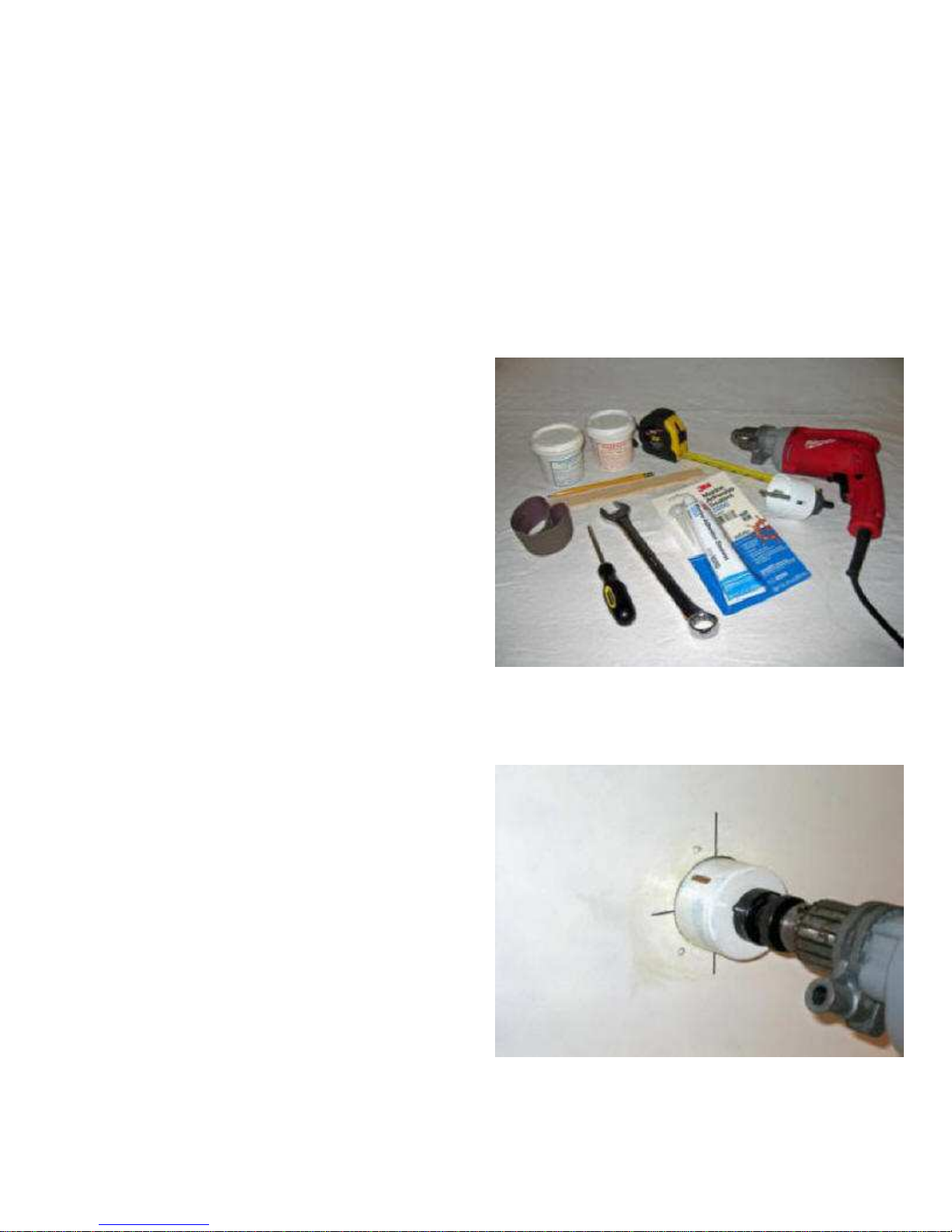
The following tools and supplies are
required for a proper install:
•
Variable speed drill
•
Hole saw
- 1.25-inch hole for the AL35 watt mini-light
- 2.5-inch hole for our AL75 lower series and the Aqua Cam
-
4.25-inch hole for our AL100 and higher series
• Tape measure
•
Pencil
•
Sand paper 180 grit
•
Phillips screw dri er
•
Wrenches
•
3M 5200 Marine adhesi e white or black de pending on your hull
color.
•
Optional two part epoxy for filling cored fiberglass essels.
•
Optional stir stick for epoxy.
•
Optional utility knife for trimming back core material.
1.
Drill hole with hole saw:
• The hole for the Aqua Light should be located a mini
mum of 6
inches below the water line for the AL75 and lower series, and 12
inches below the water line for the AL100 and higher series.
•
The Aqua Cam should be located as far below the
water line as
practical for the best iewing angle.
•
The best method is to locate your position on the hull, lea ing room
to ser ice the light with adequate room for entilation around the
fixture as the housing will warm up after prolonged use.
•
Ne er use your lights when the housing is out of the water except
when testing the light on initial install for less then 5 minutes.
•
When the location has been marked, find the same spot on the
inside of the hull and check your clearances. Then drill the pilot hole
from inside the essel,
as this will ensure the proper placement of the
light fixture.
•
Finish drilling the final hole using the proper whole saw from the
outside. Always being careful, the drill may come in contact with a
screw or other hardware that might cause the drill to jump.
•
Inspect the hull for core material. If you ha e core material, this
must be sealed to a oid the entry of water into the core. It will also
enhance the strength of the edges of the glass material.
2.
Trim core to allow room:
• Trim core to allow room for two-part epoxy or essel manufacturer
recommended material allow set.
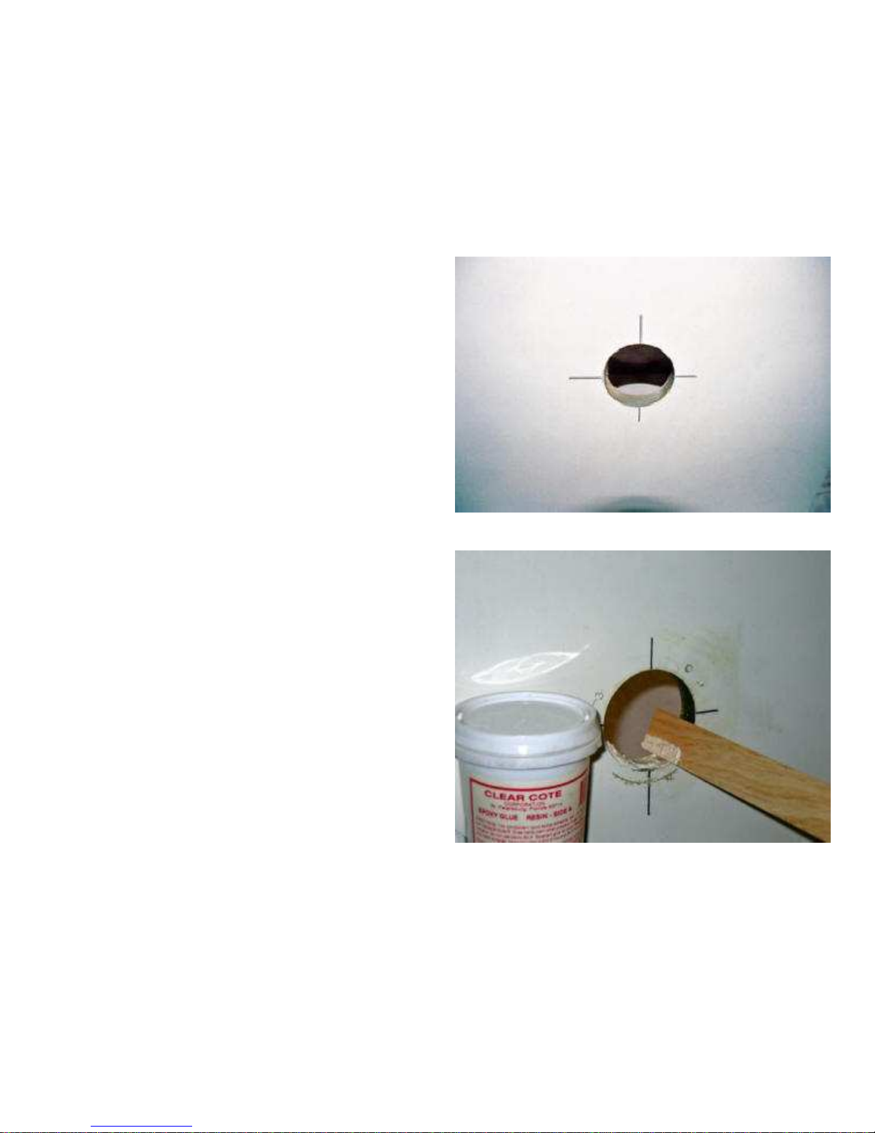
3.
Apply epoxy to dry:
• Clean core material, lea ing no isible core.
• Fill it to an e en le el amount.
• Sand clean and inspect for bubbles or pin holes.
4.
There is an O
-
ring supplied with the
light to be used when installing on
smooth level surfaces of fiberglass or
metal.
• If the surface is irregular, disregard the O-ring.
• The surface should be clean of debris and moisture at
this time, and
you should use the 180-grit sand paper to rough the adhesion points.
• Apply a generous amount of 3M 5200 Marine Adhesi e Sealant.
• A 1/2-inch bead completely around the flange and some on the
shaft of the light will be sufficient.

The adhesi e should be ejected from around the bezel
of the light.
• If it is tightened this way you know you ha e a proper seal.
5.
Insert light with a twisting motion.
• If installing the Aqua Cam, be sure to return to the top mark so that
you will ha e a proper display on your TV monitor.
6.
Tighten the locking nut.
• On some essels, if the hull is thin like a solid glass boat or
aluminum essel, make a spacer out of teak, Delron, Starboard to fill
the gap.

7.
Tighten the leveling bolts.
• Tighten the le eling bolts so that the fixture is locked into position.
Torque bolts to 30 ft lbs.
8.
Tighten SS locking bolts lock nuts.
9.
Attach light source to base.
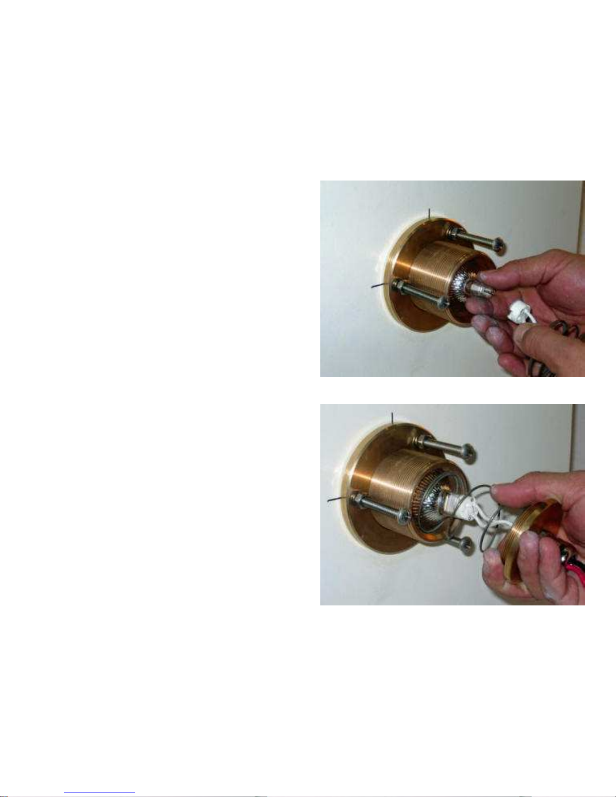
10.
Insert light source, retaining spring
into fixture.
11.
Add
light source backing.
Table of contents
Popular Light Fixture manuals by other brands


Chauvet Professional
Chauvet Professional ROGUE R1 BEAM WASH user manual

Martin
Martin MAC 250 Krypton user manual

Cooper Lighting
Cooper Lighting Halo L3232E Specification sheet

Stageline
Stageline ODW-2410RGBW instruction manual

Lightolier
Lightolier Paralyte 2424 PLA2G9LS26U specification

Lightolier
Lightolier Lytespan 83ED17S specification