NEW YORK APPROVED STEEL EMERGENCY LIGHTING UNIT
READ AND FOLLOW ALL SAFETY INSTRUCTIONS
WARNING: FAILURE TO FOLLOWTHESE INSTRUCTIONSAND WARNINGS MAY
RESULT IN DEATH, SERIOUS INJURY OR SIGNIFICANT PROPERTY DAMAGE.
For your protection, read and follow these warnings and instructions carefully before
installing or maintaining this equipment. These instructions do not attempt to cover all
installation and maintenance situations. If you do not understand these instructions
or additional information is required, contact LITHONIALIGHTING or your local
LITHONIALIGHTING distributor.
WARNING: RISK OF ELECTRIC SHOCK - NEVER CONNECTTO, DISCONNECT
FROM, OR SERVICE WHILE EQUIPMENTIS ENERGIZED.
WARNING: RISK OF FIRE. Lamps are hot. Keep combustible material away from
hot parts. Observe lamp manufacturer’s warnings, recommendations and restrictions
on lamp operation and maintenance. Make sure lamps are correctly installed.
WARNING: DO NOT USEABRASIVE MATERIALS, OR OTHER SOLVENTS. USE
OF THESE SUBSTANCES MYDAMAGE FIXTURE, WHICH MAY RESULTIN PERSONAL INJURY.
WARNING: RISK OF PERSONALINJURY- This product may have sharp edges. Wear gloves to prevent cuts or abrasions when removing from
carton, handling, installing and maintaining this product.
IMPORTANT SAFEGUARDS: When using electrical equipment, basic safety precautions should always
be followed, including the following:
• Before wiring to power supply, turn off electricity at fuse or circuit breaker.
• DisconnectA.C. power and unplug battery before servicing.
• Consult your local building code for approved wiring and installation.
• Do not use outdoors.
• Do not let power supply cord touch hot surfaces.
• Do not mount near gas or electric heaters.
• Do not install a damaged fixture.
• This product must be installed in accordance with the applicable installation codes and ordinances.
• Proper grounding is required to ensure personal safety. (WHEREAPPLICABLE)
• All service shall be performed by qualified service personnel. This product must be installed and maintained
in accordance with the applicable installation codes by a person familiar with the construction and operation
of the product and the hazards involved.
• Equipment should be mounted in locations and at heights where it will not be subject to tampering by unauthorized personnel.
• The use of accessory equipment not recommended by the manufacturer will void product listing and warranty and may cause an unsafe condition.
• Do not use this equipment for anything other than its intended use.
• CAUTION: Halogen cycle lamp(s) may be used in this fixture. To avoid shattering, do not operate lamp in excess of rated voltage. Protect
lamp against abrasions and scratches and against liquids when lamp is operating. Dispose of lamps with care. Halogen lamps operate at high
temperatures. Do not store or place flammable materials near lamps.
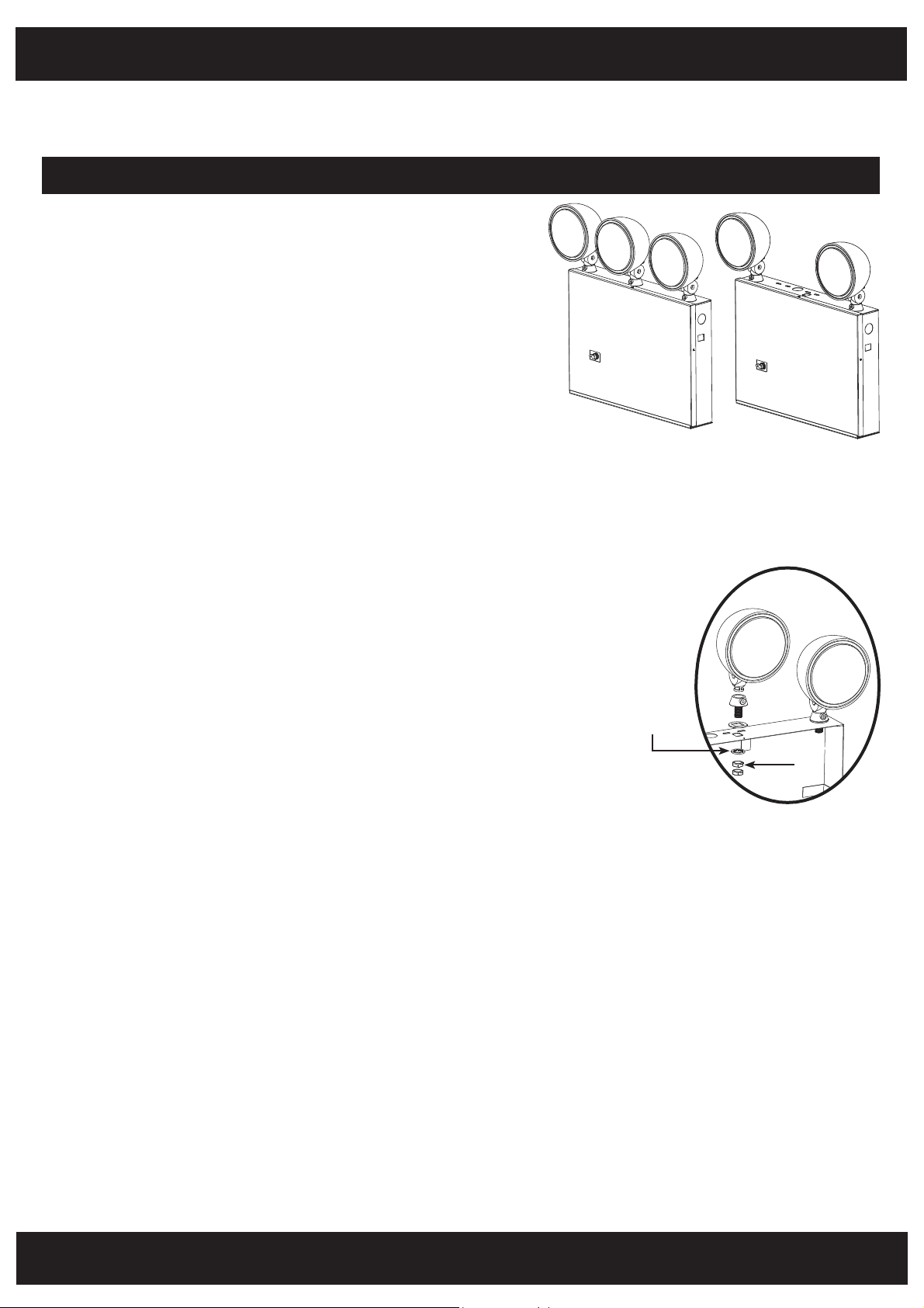
FIGURE: Lamp Head
Installation Instruction
Star Washer
Nut
INSTALLATION INSTRUCTIONS:
NOTE: Max mounting height is 8 ft to achieve at least 1 ft-candle of illuminance in emergency mode.
1. Remove the front cover.
2. Mount the equipment securely in place on the wall. Two additional KEY HOLE mounting holes are located at the top of the unit housing in addition to
the J-BOX mounting holes. These two (2) additional mounting slots must be used when the unit is mounted to the wall.Additional chain support may
be required by local codes. Chain hook holes are provided at each end of the enclosure.
3. Extend 24 hourAC supply of rated voltage to the equipment, which is furnished with a dual voltage (120/277V) field selectable input. Connect unit to
utility power using an approved connector. For 120V supply connect the line wire to the BLACK lead and for 277V supply connect the line wire to the
RED lead. Connect neutral wire to the WHITE lead. The ground wire (GREEN lead) needs to be conected in accordance with local codes. DO NOT
energize the circuit at this time.
CAUTION: Insulate the unused BLACK or RED wire. Failure to do so may cause an unsafe condition.
PAGE: 1 of 2


