3
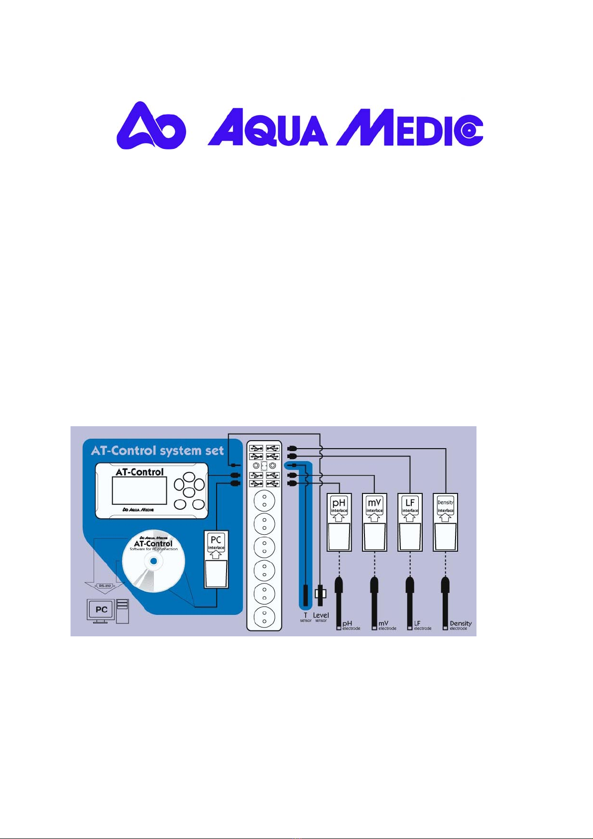
2. Connection.
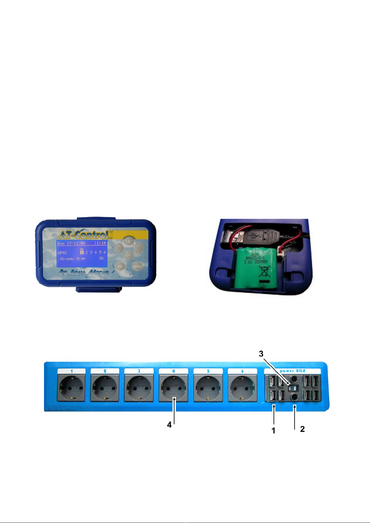
At first the batteries are placed into the controller (1) and the USB cable is connected,
before the lid is closed. Then all components are secured safely near the aquarium.
The Power Box (2) and the Controller (1) can be clipped into the holders, the Interface
Boxes (5-8) can be fixed to smooth surfaces with Velcro.
All components are now connected with the Power Box using the USB cables.
The temperature sensor (10) and if included the level sensor are directly connected
with the Power Box, using the audio jacks between the USB plugs. If more than 2
temperature or level probes are
used, an additional T/Lv- Interface
Box is needed.
All other probes are connected to
their corresponding Interface Boxes.
To reach the sockets, the Interface
Box can be opened and the sensor
can be connected to the plug. If
closed again, the sensitive
connections are protected.
Foto 5: Interface Box
If all internal connections are done, the Power Box can be connected to the mains.
The unit is switched on . One after the other, the connected sensors and components
are recognised by the controller. By pressing the Enter button, the components are
activated. Now, the corresponding measuring values are already displayed.
4. List of the Icons used in the controller
The Icons are displayed in the screen of the controller directly above the sockets and at the left lower
corner.
Attention, an alarm value is over/under
the limits Socket wave effect
Manual operation Socket tide effect
Function button is activated socket
RX Redox (ORP) socket is active (on) Agenda
pH pH socket is active (on) Agenda with sound alarm
µS Conductivity or density socket is active
(on) Summer mode
Timer socket active (on) Sound alarm activated
Temperature socket is active (on) Power Box manually blocked (switch on
“man”
Level socket is active (on) Socket blocked by blackout
Level socket is blocked ? Unknown accessory