4
CALL FOR SERVICE 480-894-0770
AquaScienceAZ.com
4
Solutions For Life
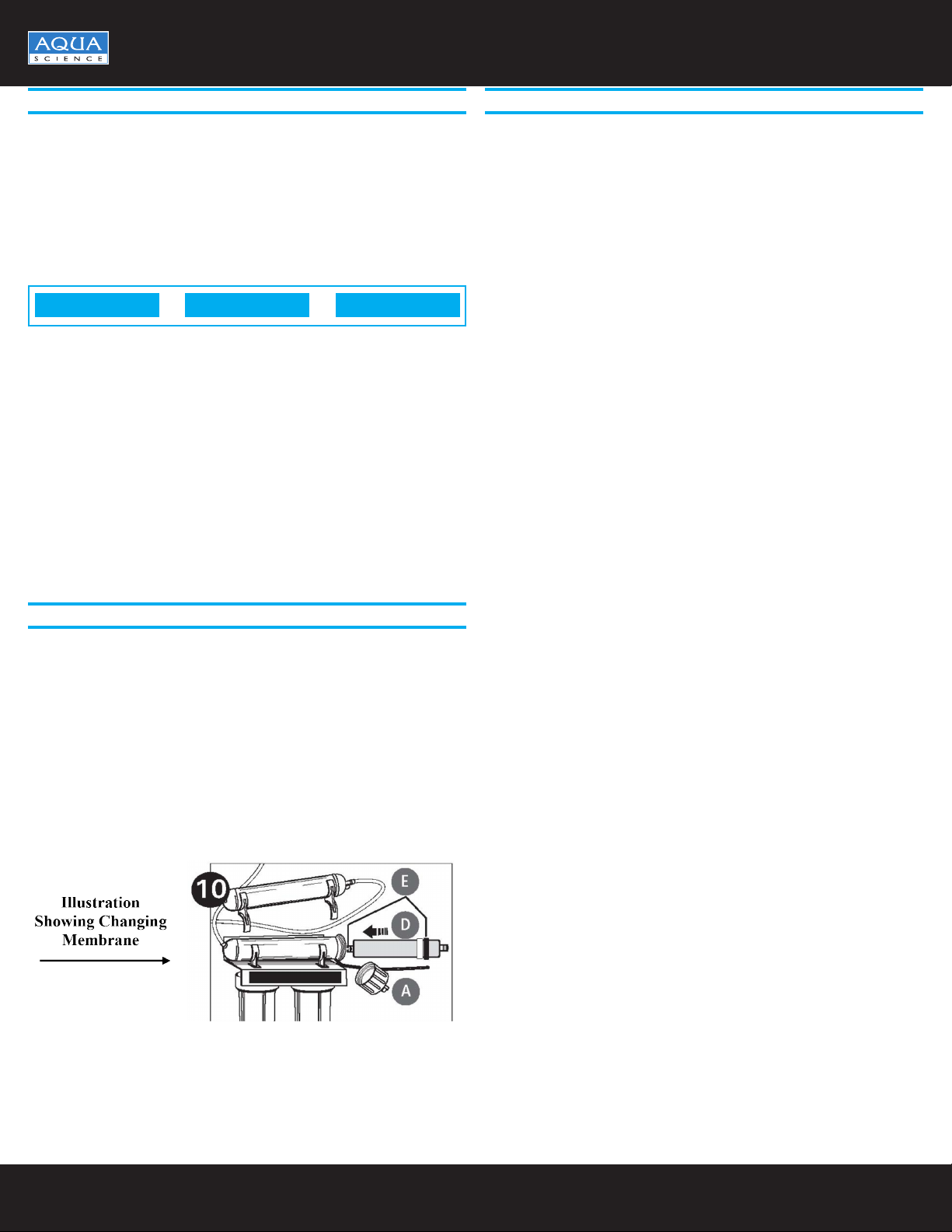
RO MEMBRANE PRECAUTIONS
Chlorine will destroy the TFC membrane. If you use this RO system
with a chlorinated or periodically chlorinated supply, it is ABSOLUTELY
NECESSARY to use a carbon pre-lter (included with the system). This
carbon pre-lter should be changed periodically to avoid chlorine bypass. See
warranty for disclaimers that apply to membrane.
NOTE: To make sure no chlorine is present in the water that reach the
membrane, you may want to use a chlorine test kit to check the water that
drains from the membrane.No chlorine should ever be detected.
HOW REVERSE OSMOSIS WORKS
The denition of reverse osmosis is to force water under pressure through
a semi-permeable membrane. Thereby the membrane reduces the salt and
minerals in your water supply. This will improve the taste and odor of your
water. The water molecule can pass through the membrane material but salt
and minerals are rejected and sent to the drain.
Your water supply is pre-ltered to remove the dirt and chlorine that may
foul the membrane. The RO membrane separates this pre-ltered water into
Product Water and Drain or Rejected Water. Incoming water pressure forces
product water through the membrane and into the storage tank. Dissolved
solids, salts, and other contaminants cannot pass through the membrane
and are sent to the drain as rejected water. When you draw water from your
RO faucet, product water is drawn from the storage tank and is run through
the post lter where it is polished to remove anything that may be left. This
provides you with great tasting, cleaner water for your drinking pleasure.
The storage tank can hold approximately 2.8 gallons of water at a time for
your water needs.
BASIC INSTALLATION PROCEDURE GUIDELINES
• For standard, under-sink installation on 3/8-inch steel, brass or copper cold
water supply line.
• Please read all instructions and precautions before installing and using
your new RO System.
• All local codes should be followed. Should the products we supply with the
unit not meet local codes, consult local plumbing supply house for correct
ttings to connect the system.
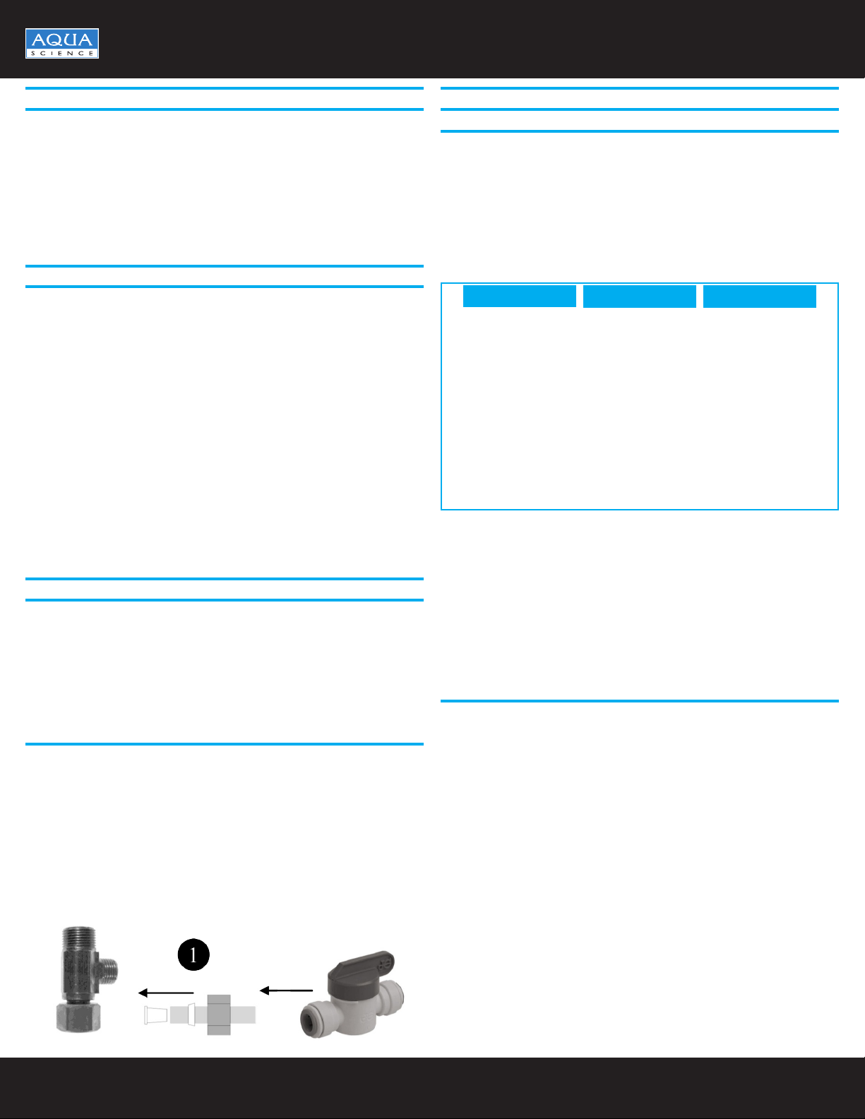
1. Installing the Water Supply Adapter
Directions
1. First shut off the cold water angle stop supply valve stopping the ow of
water. Should there not be a shut-off valve on this supply line, you should
install one.
2. Turn on cold water faucet and allow the water to drain from line.
3. Remove the supply line that runs up to the faucet. Install the brass swivel
adapter (supplied with the unit).
4. Install the brass compression nut, insert, ferrule, and plastic shut-off ball
valve (Illustration #1), supplied with the unit. After this is complete, turn the
water back on at the angle stop and check for leaks.
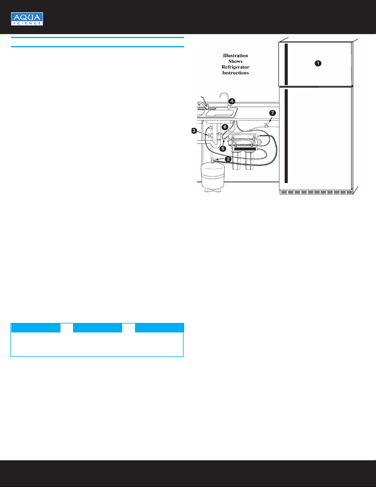
INSTALLATION (CONTINUED)
2. Selecting the Faucet Location
The drinking water faucet should be positioned with function, convenience
and appearance in mind. An adequate at area is required to allow faucet
base to rest securely. The faucet ts through a 3⁄4-inch hole. Most sinks
have pre-drilled 1 1⁄2-inch or 1 3⁄8-inch diameter holes designed for spray
hoses. The drinking water faucet may be installed using one of these holes,
despite their larger size. If these pre-drilled holes cannot be used or are in an
inconvenient location, it will be necessary to drill a 3⁄4-inch hole in the sink or
through countertop next to the sink for the faucet. Non Air-Gap faucets are
available when required and they would only require a 1/2-inch hole.
• This procedure may generate dusts which can cause severe irritation if
inhaled or come in contact with the eyes. The use of safety glasses and
safety mask for this procedure is recommended.
• Do not attempt to drill through an all-porcelain or porcelain-coated sink. For
applications on these types of sinks we recommend using the sprayer hole
or mounting the faucet through the countertop.
• When drilling through a countertop make sure the area below the drilled
area is free of wiring and piping. Make certain that you have ample room to
make the proper connections to the bottom of the faucet.
• Do not drill through a countertop that is more than 1 inch thick.
• Do not attempt to drill through a tiled, marble, granite or similar countertop.
Consult a plumber or the countertop manufacturer for advice or assistance.
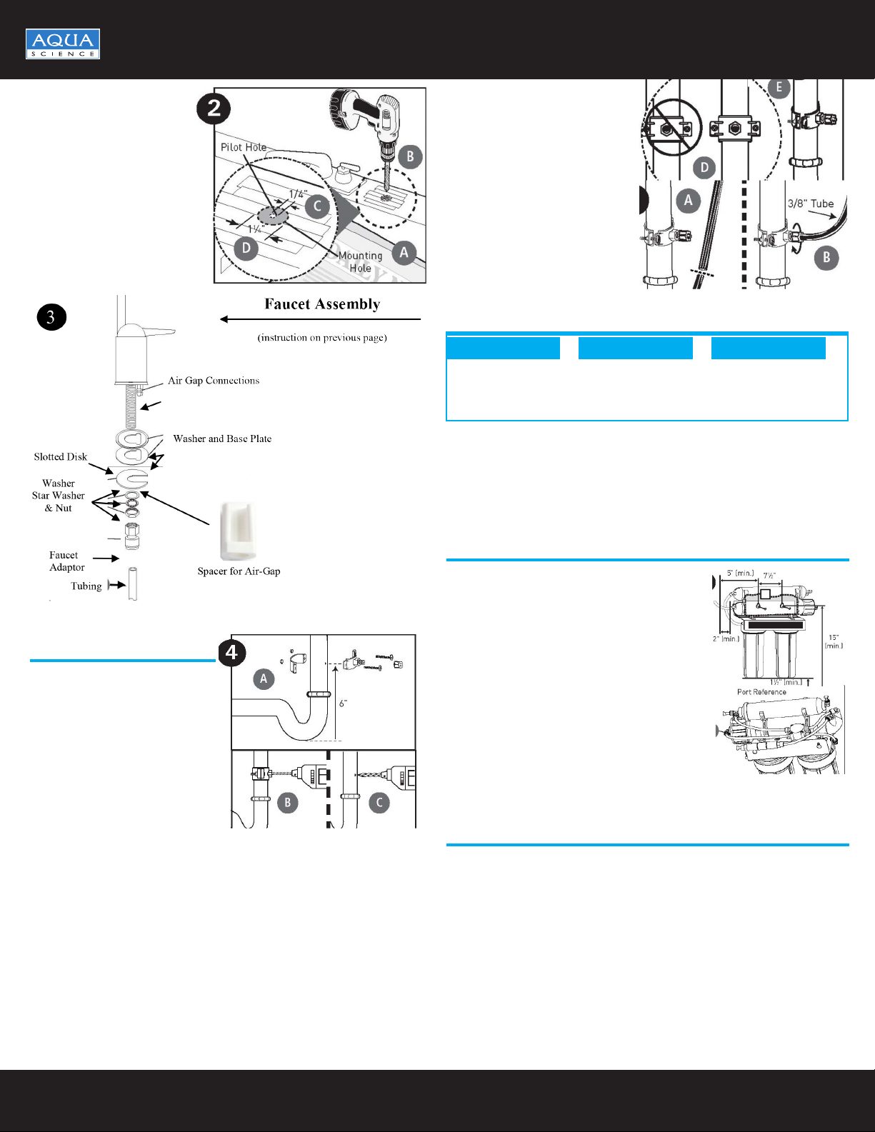
CAUTION
(SEE ILLUSTRATION #2 (next page)
The following instructions apply to stainless steel sinks ONLY.
1. Line bottom of sink with newspaper to prevent shavings, parts or tools from
falling down the drain.
2. Place masking or duct tape over the area to be drilled to help prevent
scratches if drill bit slips.
3. Mark point with center punch. Use a 1/4-inch drill bit to drill a pilot hole
through sink.
4. Use a 11⁄4-inch hole saw to enlarge hole. Smooth rough edges with a le.
3. Mounting the Faucet
1. Loosen stem-nut on faucet, remove metal slotted disc (if attached).
2. Attach large diameter 3/8-inch drain tube to barb tting at the faucet base.
This tube should be long enough to reach the drain clamp. This is a gravity
drain and should free ow to drain saddle.
3. Attach small diameter 1/4-inch drain tube to other barb tting at faucet
base. This tube should be the black 1/4-inch drain line from the RO
Assembly Drain.
4. Slide faucet plate and black rubber washer onto faucet by threading both
drain tubes through the holes on the plate and washer.
5. Slide white extension onto long threaded section of faucet. Open end of
extension should come in contact with base of faucet.
6. Apply 3-5 wraps of plumber tape to faucet stem. Screw quick connector
onto end of threads.
7. Wet end of 3/8” tube. Push into bottom of connector. Tug gently to be sure
connection is complete.
NOTE: To remove the tube, push on the ttings’ collar and pull the tube out.
8. Holding the faucet, feed the three tubes through the hole in the sink.
Position the faucet handle at a desired location
9. Center the faucet and slip slotted disc between the white extension and the
bottom of the counter or sink. Tighten the stem nut with a wrench until it is
tight.
10. Firmly insert goose-neck spout into faucet base
CAUTION CAUTION