Aqua Systems PST-20G-i User manual

1
INSTRUCTION MANUAL
1:1 RATIO
Air–operated piston transfer pump for high viscosity fluids.
1.2 MPa, 12.4 bar (180 psi) Maximum Air Input Pressure
1.2 MPa, 12.4 bar (180 psi) Maximum Fluid Working Pressure
PST-20G-i
[GRACO: 237-133]
PST-20SUS-i
[GRACO: 237-129]
Important Safety Instruction
Read all warning and instructions in this manual. Store
the manual. Refer to page 4 for a list of pump models.
Drum Can Pump

2
Symbols
Warning Symbol
Caution Symbol
WARNING
CAUTION
This symbol alerts you to the possibility of
serious injury or death if you do not follow
the instructions.
This symbol alerts you to the possibility of
damage to or destruction of equipment if
you do not follow the instructions.
WARNING
INSTRUCTIONS
EQUIPMENT MISUSE HAZARD
Equipment misuse can cause the equipment to rupture or malfunction and result in
serious injury.
⚫This equipment is for professional use only.
⚫Read all instruction manuals, tags, and labels before operating the equipment.
⚫Use the equipment only for its intended purpose. If you are uncertain about
usage, call your distributor.
⚫Do not alter or modify this equipment. Use only genuine parts and accessories.
⚫Check equipment daily. Repair or replace worn or damaged parts immediately.
⚫Do not exceed the maximum working pressure stated on the equipment or in
the Technical Data for your equipment. Do not exceed the maximum working
pressure of the lowest rated component in your system.
⚫Use fluids and solvents, which are compatible with the equipment, wetted
parts. Refer to the Technical Data section of all equipment manuals. Read the
fluid and solvent manufacturer’s warnings.
⚫Securely mount the pump. Do not attempt to operate it while holding it.
⚫Do not use hoses to pull equipment.
⚫Route hoses away from traffic areas, sharp edges, moving parts, and hot
surfaces. Do not expose hoses to temperatures above 82℃or below –40℃.
⚫Wear hearing protection when operating this equipment.
⚫Do not lift pressurized equipment.
⚫Comply with all applicable local, state, and national fire, electrical, and safety
regulations.

3
WARNING
FIRE AND EXPLOSION HAZARD
Improper grounding, poor ventilation, open flames or sparks can cause a hazardous
condition and result in a fire or explosion and serious injury.
⚫Use a ground wire for the liquid container and the device itself. Refer to
Grounding the System on page 5.
⚫If you notice static sparking or if you experience an electric shock while using
the device, immediately discontinue the operation. Do not use the
equipment until you identify and solve the problem.
⚫Provide fresh air ventilation to avoid the buildup of flammable fumes from
solvents or the fluid being dispensed.
⚫Keep the dispensation area free of debris, including solvent, rags, and gasoline.
⚫Unplug all the equipment in the dispensation area from the electric power
source.
⚫Extinguish all open flames or pilot lights in the dispensation area.
⚫Do not smoke in the dispensation area.
⚫Do not turn on or off any light switch in the dispensation area while operating or
if fumes are present.
⚫Do not operate a gasoline engine in the dispensation area.
TOXIC FLUID HAZARD
Hazardous fluid or toxic fumes can cause serious injury or death if splashed in the
eyes or on the skin, inhaled, or swallowed.
⚫Know the specific hazards of the fluid you are using.
⚫Store hazardous fluid in an approved container. Dispose of hazardous fluid
according to all local, state and national guidelines.
⚫Any additives to the air supply, such as oil or anti–freeze will be exhausted into
the atmosphere.
⚫Always wear protective eyewear, gloves, clothing and respirator as
recommended by the fluid and solvent manufacturer.
MOVING PARTS HAZARD
Moving parts can pinch or amputate your fingers.
⚫Keep clear of all moving parts when starting or operating the pump.
⚫Before servicing the equipment, follow the Pressure Relief Procedure on page
8 to prevent the equipment from starting unexpectedly.

4
2. Air hose and liquid hoses: use only
electrically conductive hoses.
3. Air compressor: according to
manufacturer’s recommendations.
4. Delivery valve: grounding is obtained
through connection to a properly grounded
fluid hose and pump.
6. Fluid supply container: according to local
code.
7. Object being sprayed: according to local
code.
8. All solvent pails used when flushing,
according to local code. Use only metal pails,
which are conductive. Do not place the pail
on a non-conductive surface, such as paper
or cardboard, which interrupts the grounding
continuity.
Installation
General Information
⚫The Typical Installation shown in Fig. 2 is only a guide for
selecting and installing system components. Contact your
Graco distributor for assistance in planning a system to suit
your needs.
⚫Always use Genuine Graco Parts and Accessories.
⚫Reference numbers and letters in parentheses refer to the
callouts in the figures and the parts lists.
Grounding the System
To reduce the risk of static sparking, ground the pump and all
other equipment used or located in the pumping area. Check
your local electrical code for detailed grounding instructions
for your area and type of equipment. Ground all of this
equipment.
1. Remove the ground screw (Z). Insert one exposed end of
a ground wire (Y) through the eye of the ground terminal
connector and tighten screw securely. Connect the other
end of the wire to a true earth ground. Order Part No.
222-011 Ground Wire and Clamp.
WARNING
FIRE AND EXPLOSION HAZARD
This pump must be grounded. Before
operating the pump, ground the system as
explained below. Also read the section
FIRE AND EXPLOSION HAZARD on
page 3.

5
Installation
Mounting the Pump
Always rigidly mount the pump to suit the type of installation planned. Graco mounting accessories are shown in the
Accessories section. With 200 liter (55 gallon) drum length pumps, screw the bung adapter (B) tightly into the bung
hole of the drum and adjust to hold the pump 13 mm (0.5 in.) off the bottom of the drum. Loosen the vent plug (A) to
prevent formation of a vacuum in the drum. Stubby pumps may be mounted on a wall or on the side of a drum with a
clamp. Drum pumps can also be mounted to the side of a drum.
NOTE: Refer to Dimensions section for pump dimensions, and air inlet and liquid outlet sizes.

6
Installation
System Accessories
Refer to Fig. 2 and the Accessories section. NOTE: To ensure maximum pump performance, be sure that all
accessories used are properly sized to meet your system’s requirements. Most models are supplied with a
needle-type air control valve (K) at the pump air inlet. All models are supplied with an air line quick disconnect
coupler (L) to connect the air line to the pump and accessories.
WARNING
A bleed-type master air valve (D) and a fluid drain valve (G) are
required in your system, to help reduce the risk of serious injury,
including splashing fluid in the eyes or on the skin, and injury
from moving parts if you are adjusting or repairing the pump.
The bleed-type master air valve (D) relieves air trapped between
this valve and the pump after the pump is shut off. Trapped air
can cause the pump to cycle unexpectedly and result in serious
injury, including amputation. Locate the valve close to the pump.
The fluid drain valve (G) helps relieve pressure in the
displacement pump, hose, and dispensing valve when shutting
off the pump. Actuating the dispensing valve to relieve pressure
may not be sufficient, especially if there is a clog in the hose or
the dispensing valve.
Using a suitable adapter, install the male disconnect pin
fitting (J) in the air filter inlet. Install the air line quick
disconnect coupler (L) on the air hose (F), but do not
connect it to the pin fitting yet. Connect an electrically
conductive fluid hose (M) to the 3/4 npt(f) fluid outlet.
For automatic air motor lubrication, install an air line
lubricator (C) downstream from the air regulator (if
supplied) and all other accessories. Install a bleed-type
master air valve (D) close to the pump. Next, install the air
regulator (CC), if supplied. Install an air line filter (E)
upstream from all other accessories, to remove harmful
dirt and moisture from the compressed air supply.

7
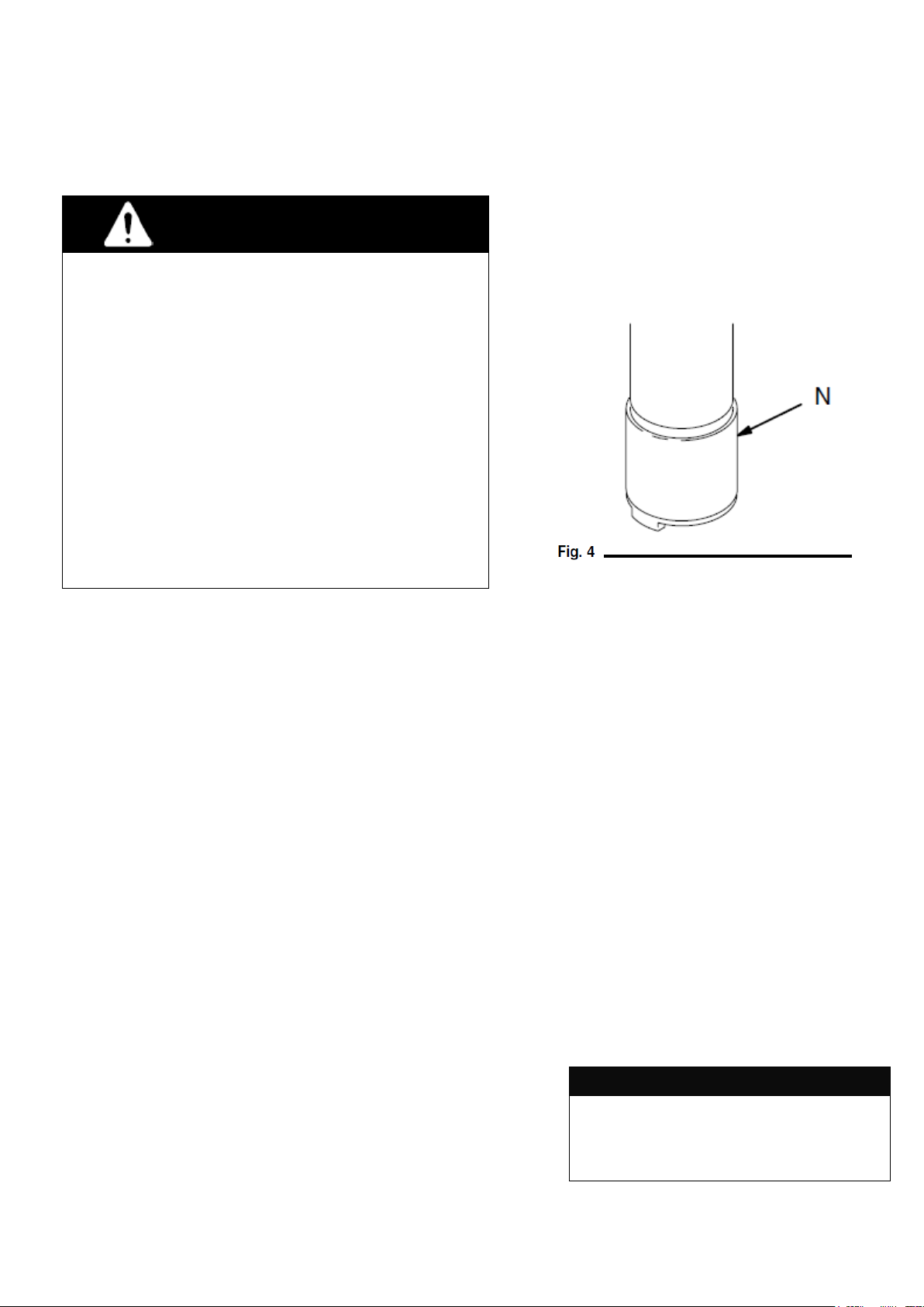
Cycle the pump slowly for at least 5 minutes, then
stop and disconnect the air hose. Push up on the
ball of the intake valve (N) to drain the lower part
of the pump. See Fig. 4. Turn the pump over to
drain the upper part of the pump.
Starting and Adjusting the Pump
With the air valve (K) or regulator (CC) closed, turn on
the air supply and connect the air line coupler (L). See
Figs. 3 or 5. Make sure all dispensing valves are open.
Slowly open the air valve (K) or regulator (CC) until the
pump cycles 5 to 20 cycles per minute. The pump itself
only takes a few strokes to prime. In a large system,
however, the pump may have to be cycled for several
minutes to fill all the lines. Once the entire system is
primed, use the air valve or regulator to control pump
speed and cycle rate; always use the lowest pressure
necessary to get the desired results. When used for
transfer and supply operations with no dispensing
valve, the pump will run whenever air is supplied.
Pump Shutdown
WARNING
To reduce the risk of serious injury whenever you are
instructed to relieve pressure, always follow the
Pressure Relief Procedure at left.
1. Disconnect the air line coupler (L).
2. Relieve the pressure.
Operation
Pressure Relief Procedure
1. Shut off the air to the pump.
2. Close the bleed-type master air valve (required in your system).
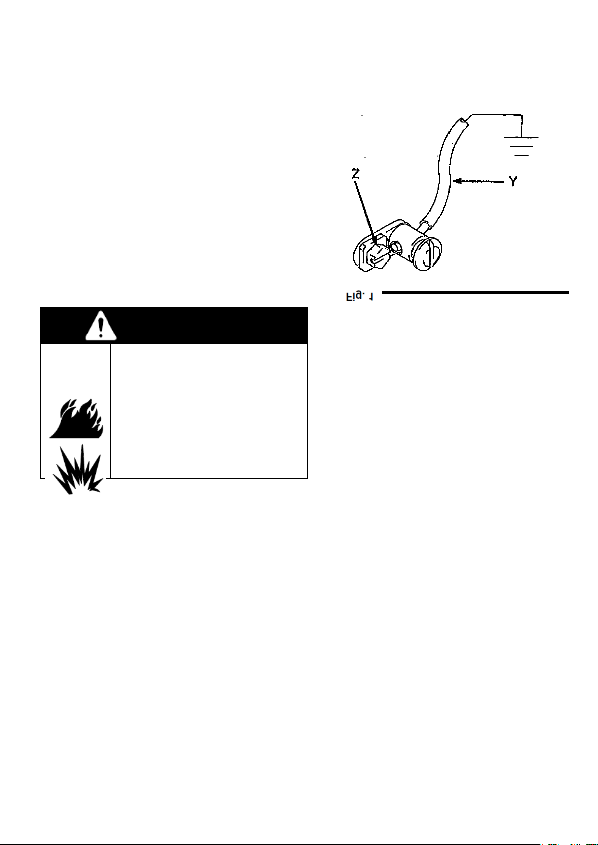
3. Hold a metal part of the dispensing valve firmly to the side of a
grounded metal pail, and trigger the valve to relieve pressure.
4. Open the fluid drain valve (required in your system) to relieve all
fluid pressure, having a container ready to catch the drainage.
5. Leave the drain valve open until you are ready to dispense
again.
If you suspect that the nozzle or hose is completely clogged, or that
pressure has not been fully relieved after following the steps above,
very slowly loosen the hose end coupling and relieve pressure
gradually, then loosen completely. Now clear the nozzle or hose.
Flush the Pump Before Using
The pump was tested in lightweight oil, which was left in to protect
pump parts. To prevent contamination of the fluid you are pumping,
flush the pump with a compatible solvent before using it. To flush
the pump, connect a short hose to the pump outlet, insert the pump
intake into a pail of compatible solvent, direct the hose into a pail,
WARNING
PRESSURIZED EQUIPMENT HAZARD
The system pressure must be manually relieved to prevent
the system from starting or spraying accidentally. To reduce
the risk of an injury from accidental spray from the gun,
splashing fluid, or moving parts, follow the Pressure Relief
Procedure whenever you:
⚫are instructed to relieve the pressure,
⚫stop spraying,
⚫check or service any of the system equipment,
⚫or install/clean the spray nozzle.

8
Fill the wet-cup (P) 1/2 full of Graco Throat Seal Liquid
(TSL) or compatible solvent and keep it 1/2 full to keep
fluid from drying on the displacement rod and damaging
pump throat packings. See Fig. 5.
Lubricate the throat packings frequently when you are
pumping a non-lubricating fluid, or are shutting down for
more than a few days. Some pumps have a grease
fitting (DD) for this purpose. See Fig.
5. The accessory air line lubricator (C) provides
automatic air motor lubrication. To manually lubricate
the motor, disconnect the air line at the air motor inlet,
put about 15 drops of lightweight oil in the inlet,
reconnect the air line and turn on the air to blow oil into
the motor.
Never allow the pump to run dry of fluid being pumped.
A dry pump will quickly accelerate to a high speed,
possibly damaging itself. If your pump accelerates
quickly, or is running too fast, stop it immediately and
check the fluid supply. If the supply container is empty
and air has been pumped into the lines, prime the pump
and lines with fluid, or flush and leave filled with
compatible solvent. Be sure to eliminate all air from the
fluid system.
Periodically, check the tightness of the packing nut
(P). Relieve the pressure, then tighten enough to
prevent leakage; no tighter. See Fig. 5. If the leakage
can not be stopped, change the packings to prevent
exposure to the fluid being pumped.
and start the pump as explained at right. Maintenance
WARNING
Do not attempt to adjust the packing nut with the
pump operating.
WARNING
To reduce the risk of serious injury whenever you are
instructed to relieve pressure, always follow the
Pressure Relief Procedure on page 8.

9
1. Relieve the pressure.
2. Check all other possible remedies before disassembling
the pump.
Troubleshooting
PROBLEM
CAUSE
SOLUTION
The pump fails to operate.
Dirty or worn air motor.
Clean, service; see the separate
motor manual 307456.
Inadequate air supply or restricted
lines.
Clean lines or increase the air supply
(see Technical Data).
Closed or clogged air valves.
Open or clear the valves.
Clogged fluid hose or valve.
Clear the hose or valves.
Worn or damaged valves or seals.
Service the valves or seals.
The pump operates, but the output
is low on both strokes.
Clogged fluid hose or valve.
Clear the hose or valves.
Exhausted fluid supply.
Refill the fluid supply and re-prime
the pump.
Worn or damaged valves or seals.
Service the valves or seals.
The pump operates, but the output
is low on the downstroke.
Held open or worn intake valve.
Clear or service the valve.
Worn or damaged valves or seals.
Service the valves or seals.
The pump operates, but the output is
low on the upstroke.
Held open or worn piston valve.
Clear or service the valve.
Worn or damaged valves or seals.
Service the valves or seals.
Erratic or accelerated operation.
Exhausted fluid supply.
Refill the fluid supply and re-prime
the pump.
Broken air motor compression
spring.
Replace the spring.
WARNING
To reduce the risk of serious injury whenever you are
instructed to relieve pressure, always follow the
Pressure Relief Procedure on page 8.

10
1. Flush the pump.
2. Relieve the pressure. Remove the pump from its
mounting.
3. See Fig. 6. Unscrew the tie rod locknuts (103).
4. Unscrew and remove the screw (105) and barrel
(104).
5. Raise the air motor (115) away from the
displacement pump (114). Unscrew the
displacement rod (15) from the air motor connecting
rod (S).
6. To order pump parts, refer to the parts lists on
pages 12–15. Refer to pages from page 17 for
displacement pump service and parts information.
Refer to manual 307456 for air motor service and
parts information.
Reconnecting the Air Motor
1. When reconnecting the air motor, use lithium base
grease on the threads of the displacement rod (15).
Make sure the o-ring (14) is in place on the rod.
2. Insert the muffler (T) into the air motor connecting
rod (S) as shown in Fig. 6.
3. Tighten the displacement rod (15) into the air motor
connecting rod hand tight, and install the barrel and
screw set (104 and 105).
4. Apply thread sealant to the threads of the tie rods
(106). To ensure proper alignment, first thread the
tie rod locknuts (106) loosely onto the tie rods, then
torque evenly to 15 N・m.
NOTE: Removing the muffler (T) will increase both
pump flow rate and exhaust noise.
5. Reconnect the ground wire if it was disconnected during
service.
Pump Service
Disconnecting the Air Motor
WARNING
To reduce the risk of serious injury whenever you are
instructed to relieve pressure, always follow the
Pressure Relief Procedure on page 8.

11
Drum Can Pump, carbon steel
Model PST-20G-i Series A, Teflon/Leather
Packings
Pump Parts
Ref. No.
Part No.
Description
Qty
.
103
104-541
NUT, M8
3
204*
15B-249
PIN
1
104*
15B-250
SCREW
1
106
177-171
TIE ROD
3
107
190-165
FITTING, air line
1
108
206-264
NEEDLE VALVE ASSY
1
109
157-628
O-RING
1
110
165-722
BODY
1
111
166-531
WASHER
1
112
166-529
NEEDLE
1
113
190-164
AIR COUPLER
1
114
215-953
Displacement Pump, refer
to page 17, model: 237-133
1
237-449
Displacement Pump, refer
to page 19, model: 237-134
1
115
223-099
Air Motor Kit, see
instruction manual 307T456
1
116
166-532
NUT
1
117
164-698
KNOB, adjusting
1
* Keep these spare parts on hand to reduce down time.

12
Drum Can Pump, carbon steel
Model PST-20G-i Series A, Teflon/Leather
Packings
Pump Parts
Ref. No.
Part No.
Description
Qty.
1
177-152
NUT, packing
1
2*
178-543
GLAND, female
1
3*
172-487
V-PACKING; Teflon
1
4*
172-384
V-PACKING; leather
2
5*
172-385
GLAND, male
1
6
178-542
HOUSING, outlet
1
7
101-281-
FITTING, grease
1
8
104-537
O-RING; Teflon
2
9
214-583
BUNG ADAPTER ASSY,
includes items 10 and 12
1
10
172-405
BUSHING, nylon
1
11
104-542
SCREW, M8x35L
1
12
210-834
ADAPTER, bung
1
13
172-416
CYLINDER
1
14
177-156
O-RING, Viton
1
15
217-189
ROD, displacement
1
16
105-775
NUT, M14
2
17
177-150
ROD, connecting
1
18
177-168
HOUSING, valve
1
19
177-155
VALVE, piston
1
20
172-393
WASHER
1
21*
172-392
CUP, leather
1
22
177-151
PISTON
1
23
217-102
FOOT VALVE
1
*These parts are included in Repair Kit 213012,
which may be purchased separately.

13
* Keep these spare parts on hand to reduce down
time.
Pump Parts
Drum Can Pump, stainless steel
Model PST-20SUS-i, Teflon Packings
Ref. No.
Part No.
Description
Qty.
103
104-541
NUT, lock, M8
3
104*
15B-249
PIN
1
105*
15B-250
SCREW
1
106
177-170
TIE ROD
3
107
190-165
FITTING, air line
1
108
206-264
NEEDLE VALVE ASSY,
includes items 109-112, 116, 117
1
109*
157-628
O-RING
1
110
165-722
BODY
1
111
166-531
WASHER
1
112
166-529
NEEDLE
1
113
190-164
COUPLER, air line
1
114
237-253
Displacement pump,
refer to page 22
1
115
223-099
Air Motor Kit,
see instruction manual 307T456
1
116
166-532
NUT
1
117
164-698
KNOB, adjusting
1

14
Pump Parts
Drum Can Pump, stainless steel
Model PST-20SUS-i Series A, Teflon Packings
Ref. No.
Part No.
Description
Qty.
1
180-049
NUT, packing
1
2*
178-543
GLAND, female
1
3*
172-487
V-PACKING; Teflon
3
5*
172-385
GLAND, male
1
6
210-876
HOUSING, outlet
1
8
104-537
O-RING, Teflon
1
10
172-405
BUSHING, Nylon
1
11
104-587
SCREW, M8x35L
1
12
210-877
BUNG ADAPTER ASSY
1
13
178-863
CYLINDER
1
14
177-156
O-RING, Viton
1
15
217-211
ROD
1
16
105-776
NUT, M14
2
17
177-149
ROD, connecting
1
18
177-175
HOUSING, valve
1
20
172-393
WASHER
1
21*
172-489
CUP PACKING, Teflon
1
22
172-495
PISTON
1
23
218-427
FOOT VALVE
1
24
172-391
SPACER, Teflon
1
25
104-585
BALL, 22 mm
1
26
172-399
STOP-PIN
1
27
177-230
GUIDE, ball
1
28
104-586
BALL, 32 mm
1
*These parts are included in Repair Kit 213013,
which may be purchased separately.

15
CARBON STEEL DISPLACEMENT PUMPS,
with leather or Teflon packings.
This procedure covers the following displacement
pump. Refer to the parts drawings on the indicated
pages for an illustration of your pump.
⚫PST-20G-i
Before You Start
1. Disconnect the displacement pump from the air
motor as explained on page 11.
2. Be sure you have all the necessary repair parts on
hand to reduce downtime.
3. Repair Kits are available. For best results, use all
the new parts in the kit even if the old parts look
good. Refer to the parts drawing for your pump.
Intake Valve
1. Unscrew the intake valve housing (23) from the
cylinder (13), using a strap wrench. Disassemble
the valve and clean and inspect all parts.
NOTE: On Models 237254 and 237255, inspect the
ball (28) and seat in the housing (23) for wear or nicks.
2. Replace parts as necessary. Reassemble as shown
in the applicable parts drawing.
Piston Valve
1. Using a strap wrench, grip the cylinder (13) near the
outlet housing (6) and unscrew it from the housing.
Pull the cylinder down off the piston. Check the
inner surface of the cylinder for scoring or wear by
running a finger over the surface or holding the part
up to the light at an angle.
2. Loosen the lower nut (16) and unscrew the valve
housing (18) from the connecting rod (17). Unscrew
the piston stud (22).
3. Clean and inspect all piston parts. Replace parts as
necessary. Reassemble the piston parts as shown,
being sure that the lips of the u-cup packing (21) are
facing up. Screw the piston stud (22) into the valve
housing (18) and torque to 31 N・m.
4. When reassembling the piston to the connecting
rod (17), screw the connecting rod all the way into
the displacement rod (15). Tighten the upper nut
(16) against the displacement rod and torque to 33
N・m. Adjust the lower nut (16) to allow 3.1 mm free
travel for the disk (19).
Throat Packings
1. Remove the cylinder (13) and piston as explained
previously. Remove the packing nut (1) and pull the
displacement rod (15) out of the top of the outlet
housing (6). Inspect the outer surface of the
displacement rod for scoring or wear by running a
finger over the surface or holding it up to the light at
an angle.
2. Remove the throat packings from the outlet housing
(6).
3. Clean and inspect the parts for wear or damage.
Lubricate the packings before reassembly. Install
the parts one at a time, in the same position as
before. The lips of the v-packings must face down
against fluid pressure.
NOTE: On displacement pumps PST-20G install the
two leather v-packings (4) below the single PTFE
v-packing (3).
4. Leave the packing nut (1) loose until the
displacement rod (15) has been installed.
CAUTION
Insert the displacement rod from the top of the
outlethousing to prevent shearing of the packings.
5. Tighten the packing nut just enough to prevent
leaking. Overtightening can damage the packings.
6. Reconnect the displacement pump to the air motor
as explained on page 11.
Displacement Pump Service

16
210-881 Wall Mounting Bracket
Carbon Steel. See manual 307T458.
1
107-558
BOLT, M8
2
2
104-572
LOCKWASHER
2
3
172-405
BUSHING
1
4
172-428
BRACKET
1
5
172-429
CLAMP
1
210-880 Open Tank Mounting Clamp
Carbon Steel.
1
107-558
BOLT, M8
2
2
104-572
LOCKWASHER
2
3
159-056
PAD
1
4
159-057
RETAINER
1
5
172-405
BUSHING, Nylon
1
6
172-427
BRACKET
1
7
172-429
CLAMP
1
8
210-879
HANDLE
1
Bung Adapters
Included with all 210L (55 gallon) drum size pumps.
214-583 Carbon Steel
214-592 SUS
1
104-542
BOLT, M8, Carbon Steel
1
104-587
BOLT, M8, SUS
1
2
172-405
BUSHING Nylon
1
3
210-834
ADAPTER, Carbon
Steel
1
210-877
ADAPTER, SUS
1
Accessories

17
222011 Ground Wire and Clamp
7.6 m (25 ft) long
Bleed-Type Master Air Valve (Required)
2.1 MPa, 21 bar (300 psi) Maximum Working Pressure
Relieves air trapped in the air line between the pump
air inlet and this valve when closed.
107-141 3/4 npt(m x f) inlet and outlet.
107-142 1/2 npt(m x f) inlet and outlet.
218-316 Air Regulator Kit
Includes 1/8” size, 0–0.4 MPa, 0–4.2 bar (0–60 psi) air
regulator and air pressure gauge, and air quick coupler.
See page 16.
206-994 Throat Seal Liquid (TSL)
Solvent for wet-cup. 0.24 liter (8 oz.).
200-326 Drum Cover
200 liter (55 gallon) size. Drum cover mounts on top of
an open drum, with mounting for 1:1 metric pump.
101078 Y Line Strainer
3.5 MPa, 35 bar (500 psi) Maximum Working Pressure
3/4 npt(f) ports; no. 20 mesh screen.
206265 Spout
For directing fluid into pails.
Carbon steel; 3/4 npt inlet.
215965 Intake Extension Tube
Intake tube 265 mm (10.4 in.) long; screws into
bottom 1–1/2 npt(f) thread of 1:1 metric pump.
Carbon steel. See manual 307T459.
214-951 Hose and 238-651 Valve
1.2 MPa, 12 bar (175 psi) Maximum Working
Pressure 7.6 m (25 ft) long, 1/2 npt(m) x 3/4 npt(m),
electrically conductive.
Accessories

18
PST-20G-i
PST-20SUS-i
Other inlet fittings (optional):
Dimensions
PUMP MODEL
A
OVERALL LENGTH
B
PUMP LENGTH
C
FLUID INLET
D
FLUID OUTLET
PST-20G-i,
PST-20SUS-i
1315 mm
880 mm
NPT 1-1/2 (f)
NPT 3/4 (f)
PART NO.
PART NAME
MATERIAL
THREAD
DIAMETER
THREAD SHAPE
843-889
NIPPLE
Stainless Steel
NPT 1-1/2 x PT 1
Both Side MALE
843-890
NIPPLE
Carbon Steel
NPT 1-1/2 x PT 1
Both Side MALE
843-884
NIPPLE
Stainless Steel
NPT 1-1/2 x PT 1/2
Both Side MALE
843-885
NIPPLE
Carbon Steel
NPT 1-1/2 x PT 1/2
Both Side MALE

19
Technical Data
Category
Data
Recommended air operating range
0.3-1.2 MPa (3-12 bar)
Air consumption
By delivery rate: 4L/min and air supply pressure: 0.5 MPa (5 bar), approx. 50L/min
Maximum recommended pump speed,
delivery rate and liquid viscosity
100 cycles/min, 15L/min, 20,000 cP
Air inlet size
PT 1/4 (m)
Liquid inlet size
NPT 1-1/2 (f)
Liquid outlet size
NPT 3/4 (f)
Maximum operating temperature
50°C
Sound pressure level
at 100 psi (0.7 MPa, 7 bar): 72 dB(A)
at 65 psi (0.45 MPa, 4.5 bar): 70 dB(A)
Sound power level
at 100 psi (0.7 MPa, 7 bar): 82 dB(A)
at 65 psi (0.45 MPa, 4.5 bar): 81 dB(A)
Weight
Stubby Pump: 11 lbs (5 kg)
Drum Pump: 20 lbs (9 kg)
Wetted parts
For PST-20G-i model
Carbon steel, SUS303, 304, 316, leather, cadmium-plated ductile iron, Teflon, Viton
For PST-20SUS-i model
SUS303, 304, 316m Teflon, Viton
* Teflon®and Viton®are registered trademarks of DuPont.

20
Performance
This manual suits for next models
1
Table of contents
Other Aqua Systems Water Pump manuals
Popular Water Pump manuals by other brands

Gormann-Rupp Pumps
Gormann-Rupp Pumps 82E-GX240 Installation, operation, and maintenance manual with parts list

Seaflo
Seaflo 56A Series instruction manual

DIVERSITECH
DIVERSITECH ASURITY PROCP-22S installation instructions

GORMAN-RUPP
GORMAN-RUPP AMT 5586-H6 manual

Speck pumpen
Speck pumpen V Series operating instructions

Grundfos
Grundfos SEG Series instructions