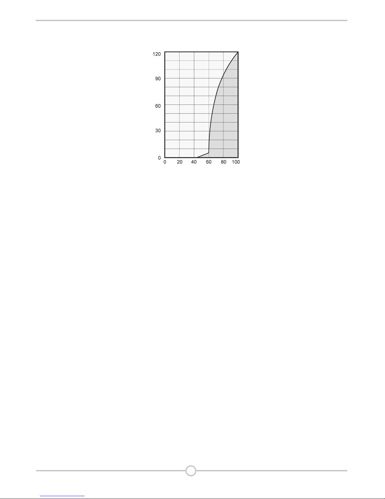
Itisevidentthatthecorrosion
ratebelow50% relative humidity
(RH) islow, and below 40%
isnegligible.
Thecorrosion rate increases
significantlyabove60% RH. This
threshold for damage as theresult
ofhumidityalsoappliestoother
materials, suchaspowdery
substances, packaging, wood
andelectronic units.
Buildingsmaybedriedinavariety
of
1. By heating and air exchange:
Theairintheroom is
heatedinorder for moisture
toberemoved and drained
outside. Alloftheenergy that
isinvolvedislosttogetherwith
themoistairthatisreleased.
2. By air dehumidification:
Themoistairthatispresent
withinanenclosedspace
iscontinuouslydehumidified
according to the condensation
principle.
Thecorrelations occurring when
airisdehumidifiedare based
onphysicallaws.
Theseare depicted here
ingraphicalforminorder
toprovide you with a brief
overviewoftheprinciplesofair
dehumidification.
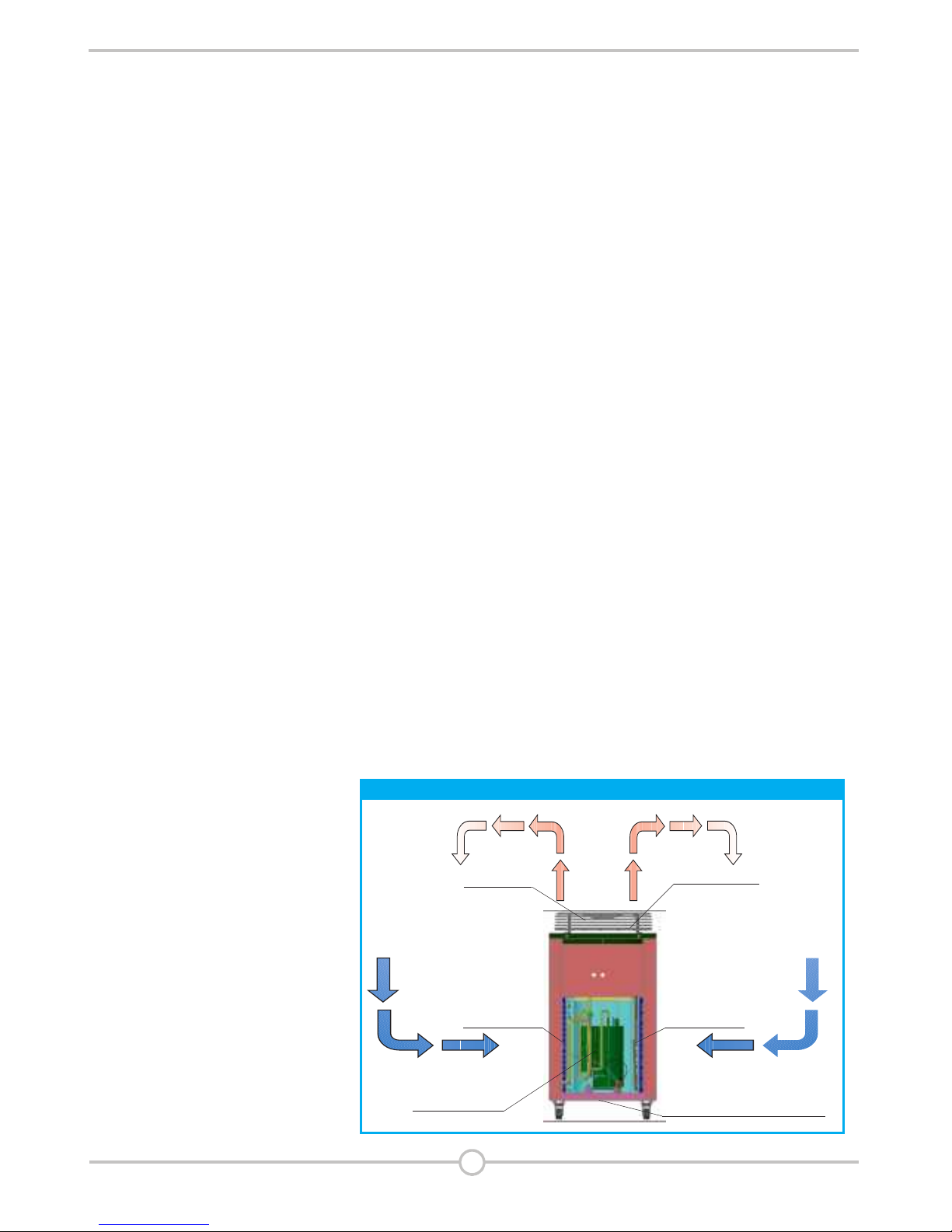
Theuseof
AQUAairdehumidifiers
EvenifWindows and doors
are well insulated, water
andmoisture are capable
ofpenetratingeventhick
concrete walls.
Thewaterrequired
forsettingintheproduction
ofconcrete, mortar and plaster
etc. mayonlybediffused after
1-2months.
Evenmoisture trapped
inthemasonryafterhigh-
waterorafoodisreleased very
slowly.
Thesame is also true ofmoisture
containedinforexamplestored
materials.
Themoisture (water vapour)
released from parts of abuilding
ormaterialsisabsorbed
bythesurrounding air. As a result,
themoisture content increases,
whichultimatelygivesrise
tocorrosion, mould, rot, peeling
ofpaintandotherunwanteddamage.
Bywayofexample, thediagram
showsthecorrosion rate of metal
indifferent levels of humidity.
Air dehumidification
With regard to energy
consumption, airdehumidification
hasonedistinctadvantage:
Energy expenditure is limited
exclusivelytotheairvolumes
present., The mechanical heat that
isreleased by the dehumidification
process is fed back into the room.
Under normal use, the air
dehumidifier uses approximately
25% of the energy that
is required for the "heating
and ventilating" principle.
Relativehumidity
Ourambientairisagaseous
mixture which always contains
acertainvolumeofwater
intheformofwatervapour.
Thisvolumeofwaterisspecified
ingperkgofdryair(absolute
moisture content).
1m3ofairweighsapprox.1.2kg
at20°C
Dependingonthetemperature,
eachkgofairisonlycapable
ofabsorbingacertainvolume
ofwatervapour. Once this
capacityhasbeenreached, the
airisreferred to as "saturated"
andhasarelative humidity (RH)
of100%.
Relativehumidityisunderstood
tomeantheratiobetween
thecurrent volume of water
vapourin the air and the maximum
possiblevolumeofwatervapour
atthesametemperature.
Theabilityoftheairtoabsorb
watervapourincreases
asthetemperature rises.
I.e. themaximumpossible
(absolute) watercontentbecomes
greater as the temperature rises.
4
Air dehumidifIers
■
■
■
■
corrosion rate
Relative humidity%