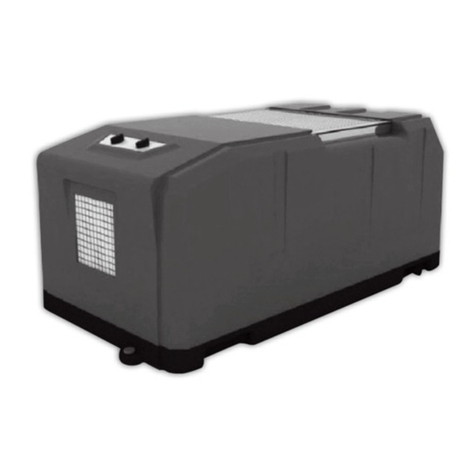
Basement Systems SD109 SaniDry XP User manual


Table of Contents
1. Specifications ................................................................................... 2
2. Installation ........................................................................................ 3
2.1 Location .................................................................................... 3
2.1A In Humid Area, No Ducting ................................................... 3
2.1B In Humid Area, Duct Inlet and/or Outlet .................................... 3
2.1C In Remote Area, Duct Inlet & Outlet ......................................3
2.1D In Remote Area, Duct Outlet Only ......................................... 3
2.1E In Remote Area, Duct Inlet Only ............................................ 3
2.2 Electrical Requirements ............................................................ 3
2.3 Condensate Removal ................................................................3
2.4 Ducting ..................................................................................... 3
2.4A Optional Ducting .................................................................. 3
2.4B Ducting for Dehumidification ................................................ 3
3. Dehumidifier Operation ..................................................................... 3
3.1 Humidity Control ....................................................................... 3
3.2 On/Off ....................................................................................... 4
3.3 Mode ........................................................................................ 4
3.4 Up/Down Arrows ....................................................................... 4
3.5 Button Press Tone ..................................................................... 4
4. LED Display ...................................................................................... 4
4.1 Run LED .................................................................................... 4
4.2 Defrost LED ............................................................................... 4
4.3 Dehumidify LED ........................................................................ 4
4.4 Fan LED .................................................................................... 4
5. Digital Display .................................................................................. 4
5.1 Digital Display Relative Humidity % ........................................... 4
5.2 Digital Display Relative Humidity % Set Point ............................ 4
5.3 Display Codes ........................................................................... 4
6. Memory/Power Failure ...................................................................... 4
7. Operating Modes .............................................................................. 4
7.1 Power Up .................................................................................. 4
7.2 Default Settings After Power Up ................................................ 4
7.3 Dehumidify Mode ...................................................................... 4
7.4 Changing Modes ....................................................................... 4
7.5 Fan Mode .................................................................................. 4
7.6 Standby Mode ........................................................................... 4
8. Protection Functions and Troubleshooting ........................................5
8.1 Defrost Protection ..................................................................... 5
8.2 Defrost Condition ...................................................................... 5
8.3 Coil Sensor Operating Properly .................................................. 5
8.4 Coil Sensor Malfunction (Digital Display Shows E1) ................... 5
8.5 Defrost Cycle ............................................................................ 5
8.6 Defrost Cycle Complete Conditions ........................................... 5
8.6A Coil Sensor Operating Properly................................................ 5
8.6B Coil Sensor Malfunction (Digital Display Shows E1) ................. 5
8.6C Defrost Cycle LED ...................................................................5
8.7 Dehumidifier Cycle Delayed Start ..............................................5
8.8 Troubleshooting the Sensors ..................................................... 5
8.8A Coil Sensor ............................................................................. 5
8.8B Humidity Sensor .....................................................................5
9. Other Functions ................................................................................ 5
9.1 Control Lock.............................................................................. 5
9.2 Display Coil Temperature .......................................................... 5
10. Electromagnetic Compatible Standard ............................................ 5
10.1 EMS Criteria ............................................................................ 5
10.2 EMC Criteria ............................................................................ 5
10.3 EMI Criteria .............................................................................5
11. Maintenance ................................................................................... 5
11.1 Air Filter .................................................................................. 5
12. Service ........................................................................................... 6
12.1 Warranty ................................................................................. 6
12.2 Technical Description .............................................................. 6
12.3 Troubleshooting ...................................................................... 6
13. Condensate Pump .......................................................................... 6
Wiring Diagram ..................................................................................... 6
Service Parts List .................................................................................. 7
Exploded Parts Diagram ....................................................................... 8
Condensate Pump Installation Instructions ............................................ 9
Ductable Inlet Mounting Detail ............................................................ 10
Filter Installation Instructions .............................................................. 10
Warranty ............................................................................................. 11
Read the installation, operation and maintenance instructions
carefully before installing and using this unit. Proper adherence
to these instructions is essential to obtain maximum benefit
from your SaniDry XP dehumidifier.
When unpacking, make sure to remove
white protective film off of filter rails.
1. SPECIFICATIONS
Model: SD109
Blower: 300 CFM @ 0.0" WG
Power: 742 watts @ 80°F and 60% RH
Supply Voltage: 115 volt – 1 phase - 60 Hz
Current Draw: 6.75 Amps
Energy Factor: 2.88 L/kWh
Operating Temp.: 40°F Min., 95°F Max.
Sized for: 2500 Sq. Ft. - Typical
Minimum Performance at 80°F and 60% RH
Water Removal: 109 Pints/Day
Efficiency: 6.09 Pints/kWh
Air Filter: MERV-11
Efficiency: Standard 65% Efficient, ASHRAE Dust Spot Test
Size: 16" x 20" x 2"
Power Cord: 10', – 110-120 VAC, Ground
Drain Hose: 9/16" ID x 8' Direct Gravity Drain Hose
SaniDry XP Dimensions
Unit With Duct Kit Shipping
Width: 19 ¾" 22 ¾" 20¼"
Height: 36 ½" 43" 43¼"
Depth: 17 ½" 17 ½" 225
/
8"
Weight: 106 lbs 122 lbs
TABLE OF CONTENTS
2SaniDry XP Installer’s & Owner’s Manual

CAUTION! — This symbol means
important instructions. Failure to heed them can result
in injury or material property damage.
2. INSTALLATION
2.1 Location
The SaniDry XP is designed to be installed indoors and is ideal for
unfinished and finished basements.
CAUTION!
• Installation outdoors, or near a pool or spa will void
factory warranty.
• Do not use the dehumidifier as a bench or table.
2.1A In humid area, no ducting.
The simplest installation is to place the SaniDry XP in the humid
area with no ducting. The air inlet on top & outlet on the side
must be at least 1’ from walls and other obstructions to air
flow.
2.1B In humid area, duct inlet and/or outlet.
If the humid area is very large or has high ceilings,
dehumidification can be improved by adding an inlet and/or
outlet duct to circulate and destratify stagnant areas. For a
large area, add inlet or outlet ducting to create flow across the
area’s greatest length. For areas with ceilings higher than 12’,
use an inlet duct to draw warm, moist air from near the ceiling.
See section 2.4 for attaching duct collars & ducting.
2.1C In A Remote Area, Duct Inlet & Outlet.
It is often desirable, in finished areas, to install the SaniDry
XP in an adjacent equipment room or unfinished area. Air is
transferred between the humid room and the unit via ducting.
The factory-mounted humidity control on the SaniDry XP
cabinet will sense the humidity in the humid room accurately
enough with this installation method.
2.1D In A Remote Area, Duct Outlet Only.
A simpler remote installation method than above uses ducting
between the SaniDry XP discharge and the humid room; the
SaniDry XP inlet draws air from the room in which it’s located.
This works well if there is an adequate air flow path between the
two rooms; i.e. high door undercut, louvered door or wall grill.
There are several potential disadvantages to using this method.
First, humid air is drawn into the room where the SaniDry XP is
located. Second, to accurately sense humidity, the blower in the
SaniDry XP may need to run continuously to draw air from the
humid room into the SaniDry XP room. Third, a slight negative
pressure is created in the room with the SaniDry XP which could
backdraft open combustion devices located there. If such devices
are present, call the factory for specific instructions before using
this installation method or consider the option 2.1E below.
2.1E In A Remote Area, Duct Inlet Only.
When the SaniDry XP is located in a room separate from the
main area to be dehumidified, it may be desirable to dehumidify
and/or slightly pressurize that room. Pressurization assures
that open combustion devices do not backdraft. This can be
accomplished by installing a duct from the humid room to the
SaniDry XP inlet and by allowing the SaniDry XP to discharge
dehumidified air into the room in which it’s located. An
adequate air flow path must exist between the two rooms for
this method to work well.
2.2 Electrical Requirements
The SaniDry XP plugs into a common grounded outlet on a 15 Amp
circuit. It draws between 6 and 7 Amps under normal operating
conditions.
2.3 Condensate Removal
Condensate drains by gravity via the clear hose extending from
the unit. Route hose to a floor drain, sump pump, or drainage
system. Use care to keep the hose as flat to the floor as possible.
Excessive humps or kinks will prevent proper drainage.
If the SaniDry XP is located too far from a floor drain for the
attached hose to reach, 1/2" PVC pipe can be used to extend
it. It is commonly available in 10’ lengths from building supply,
plumbing and hardware stores. It will slide tightly inside the end of
the drain hose.
If more than one length of pipe is required, they can be joined with
a short piece cut from the end of the drain hose.
2.4 Ducting
2.4A Optional Ducting
An inlet shroud with an 8" round collar and an 8" round
exhaust collar are available from the factory that will allow
round ducting to be attached to the inlet and/or outlet of the
SaniDry XP.
2.4B Ducting for Dehumidification
Ducting the SaniDry XP as mentioned in sections 2.1B-2.1E
requires consideration of the following points:
Duct Sizing: For total duct lengths up to 25 feet, use a
minimum 8" diameter round or equivalent rectangular. For
longer lengths, use a minimum 10" diameter or equivalent.
Grills or diffusers on the duct ends must not excessively restrict
air flow. Isolated Areas: Effective dehumidification may require
that ducting be branched to isolated, stagnant areas. Use 6"
diameter branch ducting to each of two or three areas, use 4"
to each of four or more areas.
3. Dehumidifier Operation
3.1 Humidity Control
The dehumidifier will run continuously until relative humidity
(RH) is reduced to the desired humidity level using the electronic
controller. Setting the electronic humidity controller to lower RH
levels will NOT increase the unit’s dehumidification rate - it will
simply run longer to reduce the area’s RH to the setting. The
SaniDry XP unit (and refrigerant based dehumidifiers in general)
will reduce a warm space’s RH to a lower level than that of a cool
space. For example, the SaniDry XP may reduce an 80° F space to
30% RH. However, if the same space is 65° F, it may only reduce
it to 40% RH. It is therefore pointless to set the electronic humidity
SaniDry XP INSTALLER'S AND OWNER'S MANUAL
3SaniDry XP Installer’s & Owner’s Manual

controller to excessively low levels in cool rooms. Doing so will
result in long periods of ineffective dehumidifier run time. An ideal
setting is 55%, which prevents mold growth.
3.2 ON/OFF: Pressing the ON/OFF button once will power up the
control system and illuminate the RED RUN LED. The unit will
now operate in either AUTO DEHUMIDIFY or FAN MODE. Pressing
the ON/OFF button again will return the unit to STANDBY MODE.
The RED RUN LED will flash.
3.3 MODE: Use the MODE button to select AUTO DEHUMIDIFY or
FAN mode of operation.
3.4 UP/DOWN ARROWS: Pressing the UP/DOWN arrow buttons
will display and change the desired %RH. The selectable %RH
range is 26 - 90%. These buttons will function while in either the
AUTO DEHUMIDIFY or FAN MODE.
3.5 BUTTON PRESSING TONE: Pressing any function button will
sound a tone.
4. LED DISPLAY
4.1 RUN LED: This RED indicator will flash when in STANDBY
MODE. It will remain illuminated while in either AUTO DEHUMIDFY
or FAN MODE.
4.2 DEFROST LED: This RED indicator will be illuminated while
in the DEFROST MODE, otherwise it will be extinguished.
4.3 AUTO DEHUMIDIFY LED: This GREEN indicator will be
illuminated while in the AUTO DEHUMIDIFY MODE, otherwise it will
be extinguished.
4.4 FAN LED: This GREEN indicator will be illuminated while in
the FAN MODE, otherwise it will be extinguished.
5. DIGITAL DISPLAY
5.1 DIGITAL DISPLAY RELATIVE HUMIDITY %: The digital
display will show the current %RH. in the room that the
dehumidifier is located while in stand by mode or while running in
AUTO DEHUMIDFY or FAN MODES.
5.2 DIGITAL DISPLAY RELATIVE HUMIDITY % SET POINT:
The digital display will show the % RH set point when a new
setting is selected using the UP/DOWN arrow buttons.
5.3 DISPLAY CODES: E1 indicates that the coil temperature
sensor is not functioning properly.
E2 indicates that the humidity sensor is not functioning properly.
CO indicates that the unit is running in continuous dehumidify
mode.
6. MEMORY/POWER FAILURE
If a power failure occurs, the unit will store the last selected
mode of operation and %RH settings for up to one year. When
power returns, the SaniDry XP will resume operation in the mode
previously selected.
7. OPERATING MODES:
7.1 POWER UP: When the unit is powered up, it will be in
STANDBY MODE indicated by the flashing RED RUN LED. All other
LEDs are extinguished. None of the buttons are functional except
ON/OFF. The compressor and fan will not run.
7.2 DEFAULT SETTINGS AFTER POWER UP: The control unit
displays the current %RH humidity condition of the room and sets
the %RH goal to 60%.
7.3 AUTO DEHUMIDIFY MODE: When AUTO DEHUMIDIFY MODE
is selected, the GREEN DEHUMIDIFY and RUN RED LED will be lit
and the digital display will show the current %RH of the room.
The %RH set range is 26- 90%. When the set point is lower than
the current %RH of the room, the compressor and fan will run.
When the current %RH of the room is equal to or less than the set
point, the compressor will stop. The fan will continue to run for
an additional 30 seconds. When the set point is less than 26%,
the digital display will show CO. This indicates that the unit will
dehumidify continuously.
7.4 CHANGING MODES: Press the MODE button to change the
operating mode from AUTO DEHUMIDIFY to FAN or back to AUTO
DEHUMIDIFY. The corresponding LED will be lit to indicate the
current operating mode.
7.5 FAN MODE: When the FAN MODE is selected, the fan will
run continuously, the GREEN FAN and RED RUN LED'S will be lit,
the digital display will show the current %RH of the room. The
%RH set range is 26- 90%. When the set point is lower than the
current %RH of the room, the compressor will run. When the
current %RH of the room is equal to or less than the set point, the
compressor will stop but the fan will continue to run.
7.6 STANDBY MODE: The unit will return to STANDBY MODE
each time the ON/OFF button is pressed to leave the FAN or AUTO
DEHUMIDIFY MODES indicated by the flashing RUN RED LED.
When running in FAN OR AUTO DEHUMIDIFY MODE and the %RH
set point is satisfied, the compressor will shut off, the fan will run
for an additional 30 seconds and the defrost timer will be reset. If
the ON/OFF button is pressed before the fan shuts off and the unit
returns to STANDBY MODE, the compressor will not start when the
RUN button is pressed until the this timer has run out. The control
unit does not monitor sensor information while in STANDBY
MODE.
SaniDry XP INSTALLER'S AND OWNER'S MANUAL
4SaniDry XP Installer’s & Owner’s Manual

8. PROTECTION FUNCTIONS AND
TROUBLESHOOTING
CAUTION!
ELECTRIC SHOCK HAZARD: Maintenance and repairs should be
performed by a qualified service person.
8.1 DEFROST PROTECTION
8.2 DEFROST CONDITIONS
8.3 COIL SENSOR OPERATING PROPERLY: While the
compressor is running in the AUTO DEHUMIDIFY MODE, the
control unit will monitor the coil sensor and measure how much
time it sees a coil temperature that is equal to or less than 30
˚F (-1 °C). Once that count reaches 15-minutes, the unit will
perform a DEFROST CYCLE.
8.4 COIL SENSOR MALFUNCTIONING (DIGITAL DISPLAY
SHOWS “E1”): The unit will perform DEFROST CYCLES after the
compressor has run for 53 minutes.
8.5 DEFROST CYCLE: During a DEFROST CYCLE, the compressor
will turn off, the fan motor will turn on, the RED DEFROST LED will
illuminate and the 15 minute defrost timer will be reset.
8.6 DEFROST CYCLE COMPLETE CONDITIONS
8.6A COIL SENSOR OPERATING PROPERLY: When the coil
sensor sees a temperature higher than 37 ˚F (3 °C) for 4 minutes,
the control unit will exit the DEFROST MODE.
8.6B COIL SENSOR MALFUNCTIONING (DIGITAL DISPLAY
SHOWS “E1”): The control unit will execute a DEFROST CYCLE
for 6 minutes and then exit the DEFROST MODE.
8.6C The DEFROST CYCLE LED will be extinguished.
8.7 DEHUMIDIFY CYCLE DELAYED START (COMPRESSOR
PROTECTION FUNCTION)
When the compressor stops running for any reason (%RH set point
reached, mode change, power off, power failure, etc.), it will not
restart for 3 minutes. When it starts, it will run for a minimum of 5
minutes regardless of the %RH setting.
8.8 TROUBLESHOOTING THE SENSORS
CAUTION!
ELECTRIC SHOCK HAZARD: Maintenance and repairs should be
performed by a qualified service person.
8.8A COIL SENSOR: When the coil sensor reports a temperature
that is lower than 4 ˚F (-20 °C) or higher than 158 ˚F (70 °C), the
control unit considers it faulty and will display “E1” in the digital
display. The unit will continue to run in the AUTO DEHUMIDIFY
MODE and will perform a DEFROST CYCLE every 53 minutes of
operation.
8.8B HUMIDITY SENSOR: When the humidity sensor’s output
voltage is less than 0.5V or more than 4V, the control unit
considers it faulty and will display “E2” in the digital display. The
unit will run continuously in the AUTO DEHUMIDIFY MODE or FAN
MODE and will perform a DEFROST CYCLE as required.
9. OTHER FUNCTIONS
9.1 LOCK: In the RUN mode, pressing the UP/DOWN buttons
together for 2 seconds will lock the control. None of the buttons
will function except ON/OFF. A decimal point will appear
indicating this condition. Pressing the UP/DOWN arrow buttons
together for 2 seconds again will unlock the control and restore
the all button functions.
9.2 DISPLAY COIL TEMPERATURE:
In the RUN mode, pressing the UP arrow button and the MODE
button together for 2 seconds will display the coil temperature.
Pressing the UP arrow button and the MODE button together for
2 seconds again will return the display to the current %RH of the
room.
10. ELECTROMAGNETIC COMPATIBLE
STANDARD
10.1 Meets EN61000-3 electromagnetic compatible EMS criteria
10.2 Meets IEC6100C-4 electromagnetic compatible EMC criteria
10.3 Meets CISPR14 electromagnetic compatible EMI criteria
11. Maintenance
11.1 Air Filter
The SaniDry XP is equipped with two (2) air filters. An aluminum/
foam pre-filter followed by a standard MERV-11 65% efficient
pleated fabric filter. These should be checked every six months.
Operating the unit with dirty filters will reduce dehumidifier
capacity and efficiency and may cause the compressor to cycle off
and on unnecessarily.
If dirty, the aluminum/foam prefilter can be vacuumed or carefully
hand washed with warm water and mild detergent then rinsed.
The pleated fabric filter can generally be vacuumed clean several
times before needing replacement. Replacement filters can be
ordered from your local Basement Systems dealer. DO NOT
operate the unit without the filters or with a less effective filter.
The heat exchange coils inside the unit could become clogged and
require disassembly to clean.
SaniDry XP INSTALLER'S AND OWNER'S MANUAL
5SaniDry XP Installer’s & Owner’s Manual

12. SERVICE
CAUTION!
Servicing the SaniDry XP with its high-pressure refrigerant
system and high-voltage circuitry presents a health hazard
which could result in death, serious bodily injury, and/or
property damage. Only qualified service people should service
this unit.
12.1 Warranty
A warranty certificate has been enclosed with this unit. Read
it before any repair is initiated. If a warranty repair is required,
call the factory first at 1-800-640-1500 for warranty claim
authorization and technical assistance.
12.2 Technical Description
The SaniDry XP uses a refrigeration system similar to an air
conditioner’s to remove heat and moisture from incoming air and
add heat to the air that is discharged (see Figure 1).
Hot, high-pressure refrigerant gas is routed from the compressor
to the condenser coil (see Figure 1). The refrigerant is cooled
and condensed by giving up its heat to the air that is about to be
discharged from the unit. The refrigerant liquid then passes through
a filter/drier and capillary tubing, which cause the refrigerant
pressure and temperature to drop. It next enters the evaporator coil
where it absorbs heat from the incoming air and evaporates
The evaporator operates in a flooded condition, which means that
all the evaporator tubes contain liquid refrigerant during normal
operation. A flooded evaporator should maintain constant pressure
and temperature across the entire coil, from inlet to outlet.
The mixture of gas and liquid refrigerant enter the accumulator
after leaving the evaporator coil. The accumulator prevents any
liquid refrigerant from reaching the compressor. The compressor
evacuates the cool refrigerant gas from the accumulator and
compresses it to a high pressure and temperature gas to repeat
the process.
13. CONDENSATE PUMP
The Condensate is automatically pumped to a remote location when
the water level in the pump’s reservoir rises to close the float switch.
SaniDry XP INSTALLER'S AND OWNER'S MANUAL
SaniDry XP WIRING DIAGRAM
Figure 2: Electrical Schematic of the SaniDry XP Dehumidifier
6SaniDry XP Installer’s & Owner’s Manual

SaniDry XP SERVICE PARTS LIST • To order, contact your local Basement Systems Dealer
NO DESCRIPTION QTY SPECIFICATIONS
1 Wheel 4
2 Plate, Bottom 1 Galvanized steel (1.5mm)
3 Bracket 4 Galvanized steel (1.0mm)
4 Grommet, rubber – compressor 3 Buna N
5 Washer, plate 3 6mm dia. Steel
6 Nut 3 M6 steel
7 Capacitor, compressor 1 35µF/250V
8 Compressor 1 5RS080UAA21 115VAC/60HZ R410A
9 Gasket, cover – terminal 1 EPT
10 Spring, hold down 1 SS
11 Overload protector 1 B290-150-241H
12 Cover, terminal 1 PET
13 Gasket, nut 1 5mm dia PET
14 Cover, terminal – nut 1 M5 steel
15 Seal, lower - condenser 1 PU
16 Seal, side – condenser 2 PU
17 Condenser 1
18 Seal, upper – condenser 1 PU
19 Trough, collection - water 1 SS
20 Probe, temperature 1
21 Evaporator 1
22 Seal, heat exchanger - vertical 4 PU
23 Seal, heat exchanger - horizontal 2 PU
24 Probe, humidity 1
25 Cover, probe - humidity 1 ABS
26 Heat exchanger 1 PP
27 Guide, filter 2 SS (0.6mm)
28 Seal, guide 2 PU
29 Cabinet 1 Powder-coated steel (1.0mm)
30 Bracket, evaporator 1 SS (0.6mm)
31 Tubing, evaporator 1 9.52mm OD x .8mm wall copper tubing
32 Grommet 1 Buna N
33 Capillary 2 2.5mm OD x 1.0mm wall
34 Tubing, discharge 1 6.35mm OD x .8mm wall copper tubing
35 Filter 1
36 Tubing, process 1 6.35mm OD x .8mm wall copper tubing
37 Tubing, condenser 2 9.52mm OD x .8mm wall copper tubing
38 Insulation 1 PE
39 Tubing, suction 1 9.52mm OD x .8mm wall copper tubing
40 Line cord 1 3 wire 16AWG/125V/13A/105˚C/300V
41 Cordgrip 1 ABS
42 Grommet 1 Buna N
43 Screen, fan 1 Steel
44 Control unit 1 115V/60Hz
45 Insulation, trough – water collection 1 PE
46 Damper, mass 1
47 Housing, fan 1 Powder-coated steel (1.0mm)
48 Motor, fan 1 115V/60Hz
49 Washer, motor - fan 1 Silicon Rubber 97mm OD x 7mm thick
50 Capacitor, fan 1 12.5µF/250V
51 Isolator, vibration - fan 1 PE
52 Rotor, fan 1 Aluminum
53 Deflector, air 1 Powder-coated steel (1.0mm)
54 Wire 1 16-20AWG/105˚C/600V/VW-1
55 Clamp, tubing 1 SS
56 Tubing, drain 1 16mm ID x 1.8m PVC
57 Cover, cabinet 1 Powder-coated steel (1.0mm)
58 Insulation, cover - cabinet 1 PE
59 Insulation, cabinet - lower 2 PE
60 Insulation, cabinet - upper 2 PE
61 Filter, pleated – paper 1
62 Filter, aluminum 1
7SaniDry XP Installer’s & Owner’s Manual

SaniDry XP SERVICE PARTS LIST • To order, contact your local Basement Systems Dealer
8SaniDry XP Installer’s & Owner’s Manual
Exploded View

SaniDry XP CONDENSATE PUMP INSTALLATION INSTRUCTIONS
STEP 1: The condensate pump kit
includes: 25' drain hose, drain hose clamp,
condensate pump, two mounting screws and
instructions.
STEP 4: Pull discharge hose out of unit until it
stops. Cut the condensate drain hose at a 45°
angle approximately 10 inches from the unit.
STEP 7: Insert the drain hose into the
condensate pump reservoir as shown.
STEP 2: Predrilled mounting holes are located
near the bottom and on the same side of the
unit as the drain hose.
STEP 5: Example of hose cut at a 45° angle.
The angle prevents the hose from sealing tight
against the bottom of the pump reservoir.
STEP 8: Install the provided drain hose over the
condensate pump nipple. Tighten hose clamp.
STEP 3: Secure the condensate pump to the
unit with the two provided screws.
STEP 6: Remove the plug as shown.
STEP 9: Route the condensate pump drain hose
to an appropriate drain and plug the condensate
pump into a standard 115VAC outlet.
9SaniDry XP Installer’s & Owner’s Manual

Ductable
Inlet
Exhaust
Collar
SaniDry XP DUCTABLE INLET MOUNTING
Ductable Inlet Instructions
1. Remove the Filters from the unit.
2. Remove the ductable inlet from the box and remove the
release paper from the tape on the inlet flanges.
3. Center the inlet above the filter guides and attach the inlet to
the guides.
4. Replace the filters in the unit.
Exhaust Collar Mounting Instructions
5. Remove the exhaust collar from the box and bend the tabs in.
6. Place the collar over the blower outlet and line up the tabs
with the holes in the cabinet.
7. Using (4) screws from the kit, attach the collar to the unit.
collar.
Ductable
Inlet
Exhaust
Collar
10 SaniDry XP Installer’s & Owner’s Manual
SaniDry XP FILTER INSTALLATION INSTRUCTIONS
Instructions: To prevent damaging the aluminum filter, place it “mesh-side up” on top of
the pleated filter and slide them both into the filter slot.
Aluminum filter with
aluminum grid up. Pleated filter with air flow
arrows pointed down.
Pleated filter with
air flow arrows
pointed down.
Aluminum mesh filter
with aluminum grid up.

SaniDry XP Limited Warranty
11 SaniDry XP Installer’s & Owner’s Manual
Limited Warranty. Basement Systems, Inc. ("BSI") warrants as
follows: (i) the SaniDry XP dehumidifier (“Product”) will be free of
material defects in workmanship or materials for a period of thirty
months following the date of manufacture on the cabinet label.
Limitation of Remedies. CUSTOMER’S SOLE AND EXCLUSIVE
REMEDY UNDER THE ABOVE LIMITED WARRANTY AND BSI’S
ENTIRE LIABILITY THEREUNDER, SHALL BE, AT THE SOLE OPTION
OF BSI, REPLACEMENT OR REPAIR OF SUCH PRODUCT OR ITS
COMPONENTS (“COMPONENTS”) BY BSI OR BSI’S AGENTS ONLY. IF
TRANSPORTATION IS REQUIRED TO BASEMENT SYSTEMS' SERVICE
CENTER, CUSTOMER MUST PAY FOR SUCH TRANSPORTATION, AND
BASEMENT SYSTEMS WILL PAY FOR RETURN TRANSPORTATION
BACK TO AUTHORIZED BSI DEALER OR HOMEOWNER ANYWHERE IN
CONTINENTAL US OR CANADA. THIS DISCLAIMER AND EXCLUSION
SHALL APPLY EVEN IF THE EXPRESS WARRANTY AND LIMITED
REMEDY SET FORTH HEREIN FAILS OF ITS ESSENTIAL PURPOSE.
CUSTOMER ACKNOWLEDGES THAT NO REPRESENTATIVE OF BSI OR
OF ITS AFFILIATES OR RESELLERS IS AUTHORIZED TO MAKE ANY
REPRESENTATION OR WARRANTY ON BEHALF OF BSI OR ANY OF ITS
AFFILIATES OR RESELLERS THAT IS NOT IN THIS AGREEMENT.
Disclaimer of Warranties. EXCEPT FOR ABOVE LIMITED
WARRANTY, WHICH IS THE SOLE AND EXCLUSIVE WARRANTY
PROVIDED WITH RESPECT TO THE PRODUCT AND ITS COMPONENTS,
BSI HEREBY DISCLAIMS ALL EXPRESS AND IMPLIED WARRANTIES,
INCLUDING, WITHOUT LIMITATION, THE IMPLIED WARRANTIES OF
MERCHANTABILITY AND FITNESS FOR A PARTICULAR PURPOSE.
Warranty Limitations. A “defect” under the terms of the limited
warranty shall not include problems resulting from Customer’s
or Customer’s employees’, agents’, invitees’ or a third party’s
misuse, improper installation, improper design of any system in
which the Product is included, abuse, lack of normal care, failure to
follow written instructions, tampering, improper repair, or freezing,
corrosion, acts of nature or other causes not arising out of defects
in BSI’s workmanship or material. If a Product or Component is
replaced while under warranty, the applicable limited warranty
period shall not be extended beyond the original warranty time
period. The limited warranty does not cover any costs related to
changes to a Product or Component that may be required by any
codes, laws, or regulations that may become effective after initial
purchase of the Product by Customer.
Customer Responsibilities. As a further condition to obtaining
warranty coverage hereunder, the Customer must send a valid
warranty claim to BSI such that BSI receives such claim prior to the
end of the applicable warranty period. BSI shall have no obligation
hereunder with respect to any claim received by BSI after the
expiration of the applicable warranty period. Warranty service must
be performed by BSI or a servicer authorized by BSI. In order to
obtain warranty service, the Customer should call BSI at 1-800-
640-1500 and ask for the BSI Products Service Department, which
will then arrange for applicable warranty service. Warranty service
will be performed during customary, daytime working hours. If
the Product must be shipped for service, Customer shall be solely
responsible for properly packaging the Product, for all freight
charges, and for all risk of loss associated with shipment.
Limitation of Liability. IN NO EVENT SHALL BSI, IN CONNECTION
WITH THE DESIGN, SALE, INSTALLATION, USE, REPAIR,
REPLACEMENT OR PERFORMANCE OF ANY PRODUCT, COMPONENT,
PART THEREOF OR WRITTEN MATERIAL PROVIDED THEREWITH,
BE LIABLE, TO THE EXTENT ALLOWED UNDER APPLICABLE LAW,
UNDER ANY LEGAL THEORY FOR ANY SPECIAL, DIRECT, INDIRECT,
COLLATERAL OR CONSEQUENTIAL DAMAGES OF ANY KIND.
NOTWITHSTANDING THE ABOVE LIMITATIONS AND WARRANTIES,
THE SOLE AND EXCLUSIVE LIABILITY OF BSI, REGARDLESS OF
THE NATURE OR THEORY OF THE CLAIM, SHALL UNDER NO
CIRCUMSTANCES EXCEED THE PURCHASE PRICE OF THE PRODUCT,
COMPONENT OR PART UPON WHICH THE CLAIM IS PREMISED.
Applicable Law and Venue. ANY ARBITRATION, ENFORCEMENT
OF AN ARBITRATION OR LITIGATION RELATED TO THE PRODUCT
WILL BE BROUGHT EXCLUSIVELY IN NEW HAVEN COUNTY,
CONNECTICUT, AND CUSTOMER CONSENTS TO THE JURISDICTION
OF THE FEDERAL AND STATE COURTS LOCATED THEREIN, SUBMITS
TO THE JURISDICTION THEREOF AND WAIVES THE RIGHT TO
CHANGE VENUE. CUSTOMER FURTHER CONSENTS TO THE EXERCISE
OF PERSONAL JURISDICTION BY ANY SUCH COURT WITH RESPECT
TO ANY SUCH PROCEEDING.
Miscellaneous. If any term or condition of this Limited Warranty
is found by a court of competent jurisdiction to be invalid, illegal or
otherwise unenforceable, the same shall not affect the other terms
or conditions hereof or thereof or the whole of this Limited Warranty.
Any delay or failure by BSI to exercise any right or remedy will not
constitute a waiver of BSI to thereafter enforce such rights.
60 Silvermine Road
Seymour, Connecticut 06483
Web: www.BasementSystems.com
For product information go to: www.SaniDryDehumidifier.com
1-800-640-1500
Information in this document is subject to change without notice.
No part of this document may be reproduced or transmitted in any
form or by any means, electronic or mechanical, for any purpose,
without the express written permission of Basement Systems.
© 2009 Basement Systems, Inc. All rights reserved.
By
Table of contents
Other Basement Systems Dehumidifier manuals
