aquabrass Aquasteam N2787 User manual

aquabrass.com
Aquasteam N2787/N2789/N2782
steambath generator 7.5KW 9KW 12KW
générateur de vapeur 7.5KW 9KW 12KW
last revision: 10/20/2016

SteambathGeneratorSystems
INSTALLATION,OPERATION&MAINTENANCEMANUAL
Table of Contents
Read Me First! & Warning Placard .....................................1
SelectYour
!
!QUASTEAM
ȩModel.......................................2
Specification Chart .............................................................2
Before Installing .................................................................3
Steam Room Guidelines.....................................................3
Locating the Steam Generator Unit ...................................4
Typical Installation ..............................................................4
Installation: Plumbing, Water Supply, Drain, Steam Outlet
SafetyValve,DripPan,AromaSteam..............
WaterQualityInformation..................................................
*OTUBMMJOHUIF"SPNB4UFBNTUFBNIFBE..............................6
GeneratorDimensions.......................................................
ElectricalSpecifications&FieldPowerWiring..................
WiringDiagrams...............................................................
InitialStart-Up&Checkout,
.BJOUFOBODF..................................1
SystemStatusCodes,LiquidLevelControlBoard..........1
AutoFlush
®
System...........................................................1
ReplacementPartsList.....................................................1
ReplacementPartsDiagram.............................................1
Controls
CareTipsforControlsandSteamhead............................1
General
$BSF....................1
MADE IN USA
PUR
100426
REV
5.16
'JFMEQPXFSXJSJOH
5SPVCMFTIPPUJOH
Warranty...........................................................................

READ ME FIRST!
IMPORTANT NOTE:
As you follow these instructions, you will
notice warning and caution symbols. This
blocked information is important for the
safe and ecient installation and opera-
tion of this generator. These are types of
potential hazards that may occur during
this installation and operation:
states a hazard may cause serious injury
or death if precautions are not followed.
signals a situation where minor injury or
product damage may occur if you do not
follow instructions.
IMPORTANT NOTE:
This highlights
information that is especially relevant to a
problem-free installation.
All information in these instructions is
based on the latest product information
available at the time of publication.
Sussman-Automatic Corporation reserves
the right to make changes at any time
without notice.
Wheninstallingandusingthiselectricalequipment,basicsafetyprecautions
shouldalwaysbefollowed,includingthefollowing:
IMPORTANTSAFETYINSTRUCTIONS
1. READANDFOLLOWALLINSTRUCTIONS
2. Do not permit children under the age of 16
to use this steambath.
3.
To reduce the risk onjury:
A. The wet surfaces of steam enclosures may be slippery. Use care when
entering or leaving.
B. The steam head is hot. Do not touch the steam head and avoid the
steam near the steam head.
C. Prolonged use of the steam system can raise excessively the internal
human body temperature and impair the body’s ability to regulate its
internal temperature (hyperthermia). Limit your use of steam to 10-15
minutes until you are certain of your body’s reaction.
D. Excessive temperatures have a high potential for causing fetal damage
during the early months of pregnancy. Pregnancy or possibly pregnant
women should consult a physician regarding correct exposure.
E. Obese persons and persons with a history of heart disease, low or high
blood pressure, circulatory system problems, or diabetes should consult
a physician before using a steambath.
F. Persons using medication should consult a physician before using a
steambath since some medication may induce drowsiness while other
medications may aect heart rate, blood pressure and circulation.
SAVE THESE INSTRUCTIONS
1
_________________________________________________________________________________________
WARNING
!
WARNING
!
WARNING
!
CAUTION
!
HYPERTHERMIAoccurswhentheinternaltemperatureof
thebodyreaches a levelseveraldegreesabovethe
normalbodytemperatureof98.6°F. Thesymptomsof
hyperthermiaincludeanincreaseintheinternaltem-
peratureofthebody,dizziness,lethargy,drowsiness,and
fainting.Theeffectsofhyperthermiainclude:
a) Failure to perceive heat;
b) Failure to recognize the need to exit the steambath;
c) Unawareness ompending risk;
d) Fetal damage in pregnant women;
e) Physical inability to exit the steambath
and
f) Unconsciousness.
The use of alcohol, drugs, or medica-
tion can greatly increase the risk of hyperthermia.
WARNING
!

_________________________________________________________________________________________
2
In considering a purchase of this steam-
bathsystem,pleasenotethatifusersarepregnant,
haveacoronarycondition,areinpoorhealth,arebeing
treatedforanyothermedicalcondition,orareusing
medicationordrugs,$TXDVWHDPrecommendsthatyou
obtaintheapprovaloftheirphysicianbeforeuse.
IMPORTANTNOTES:
•
•
Theguidelinesforselectingthesteambathgeneratoris
arecommendationonly.Becauseofvariablesin
construction,thesesizinginstructionsandspecifica-
tionsshouldbeconsideredasguidelinesonly.
"RVBCSBTTwillreviewthemodelselectedprovidedwe
receivecompleteinformation,includingworkingdraw-
ings,specifications,andpertinentelectricalandcon-
structiondetails.Otherwise,themanufacturerdis-
claimsresponsibilityforthesizingofamodelselected
'PSTUFBNSPPNTDPOTUSVDUFEPGBDSZMJDPSTZOUIFUJD
NBUFSJBMTTFMFDUOFYUMPXFSSBUFENPEFM
• Thetotaladjustedroomvolumeallowsforupto60
feetofinsulatedsteamlinefromthegeneratortothe
steamroom.Ifthe60feetlineisexceededconsult
withfactory.Whenlocatingthesteamgenerator
considerationofthecontroltemperatureprobemust
betakenintoaccount.Themaximumlengthfora
controlcableis60feetb
Steam Generators Specification Chart
Amps (for Total Adj Wire Water Usage Shipping
Model No. KW 240v/1PH)† Room Vol. Size‡ *SP Dimensions* Wt. (lbs)**
25
8
,ȩXȩ(ȩXȩ$
9 38 360 8
12 50 575 6 17"L x 18½"H x 77⁄8"D 40
Materials of construction, room size and special design features such as
large glass areas, all affect the steam generator model selection.
1.
Measure length, width & height in feet of the steam/shower or tub/shower
Multiply the Length ____ x Width____ x Height _____ =
2. Construction Materials:
For natural stones: natural marble, Add 110%
stone, shale, glass block or concrete
For ceramic or porcelain tile on Add 40%
cement board or mortar bed
3. Ceiling Height: For each foot above 8 feetAdd 15%
4. Add all figures above to obtain
the Total Room Volume required
ROOM
VOLUME
TOTAL ADJUSTED
ROOM VOLUME
SelectYourModel
CompareyourTOTALADJUSTEDROOMVOLUMEtotheSpecificationChart
belowandselecttheappropriatemodel.
WARNING
!
,ȩXȩ(ȩXȩ$
/
/
/

_________________________________________________________________________________________
3
Never use damaged equipment, doing so
mayresultinaninoperativeorhazardousinstallation.
Discontinueuseofthesteamgeneratorandcontrolifthe
steamgeneratororcontrolaredamagedorotherwisenotfunc-
tioningproperly.Doingsomayresultinaninoperativeorhaz-
ardousinstallation
ELECTRICALSHOCKHAZARD.$TXDVWHDPsteamgeneratorsare
connectedto240Vline
voltageandcontainliveelectricalcom-
ponents.Allinstallationandservicetobeperformedbyquali-
fedandlicensedelectriciansandplumbersonly.Installationor
servicebyunqualifiedpersonsorfailuretouse"RVBTUFBN
partsmayresultinpropertydamageorin a hazardous
condition.
Do Not alter or modify any !QUASTEAM prod-
uct. Doing so may result in an inoperable or hazardous
installation and will void the warranty
BeforeInstalling
CarefullyinspecttheCTsteamgeneratorandpackagingfor
shippingdamage.Intheeventofshippingdamage,please
contactthecarrierforclaiminformation.Ourcustomer
servicedepartmentcanassistyouwithanymissingor
damagedparts.
Readtheseinstructionsbeforeinstallationorservice.
Althoughthissteamgeneratorhasbeenfullyqualifiedfor
shipment,thefollowingmustbereviewedforproper,safe
andenjoyablesteambathing:
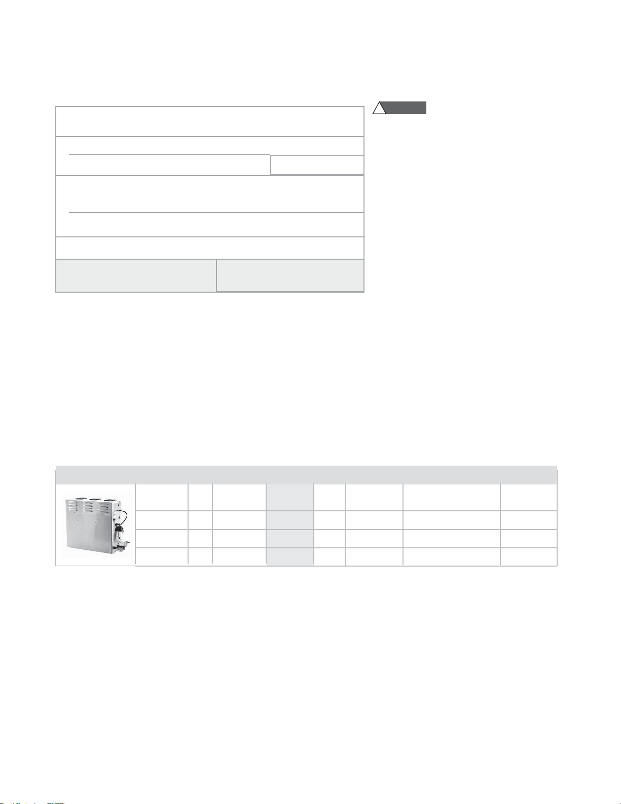
1. Verify that the model and accessories specications are
correct for the incoming line voltage.
2. Insure steambath generator has been correctly sized for
Steam Room Guidelines
1. Steam room must be completely enclosed, with full
walls, door, oor and ceiling.
2. It is recommended that a gasketed door is used for
steam containment.
3. If tile-type or other smooth surfaced ooring is used
provide suitable anti-skid strips or equivalent, to
prevent a slipping hazard.
4. Check the suitability of any materials with the
manufacturer. Walls and ceilings must be constructed
of water-resistant, non-corrosive surface, such as tile,
marble, molded acrylic, or other non-porous material.
5. The ceiling should be sloped to prevent dripping of
condensate.
6. Provide a oor drain.
7. No heating, venting or air conditioning devices
should be installed inside the steam room.
8. Steam room tile construction information is available
from the Tile Council of America, Inc. by purchasing
the TCA Handbook for Ceramic Tile Installation.
Tel. (864) 646-8453 or www.tileusa.com.
9. Windows that are part of the steam room should be
double paned and tempered safety glass.
10. Limit steam room ceiling height to 8 feet. Exceeding
8 feet may require a higher-rated steam generator.
thesteambathroom.Payparticularattentiontoroom
volumeandconstruction.
Marbleorglasswallsorceilings“enlarge”theroom’ssize
requiring a generatorlargerthanonebasedonlyonthe
room’scubicfoot(LxHxW)volume.
Thephysicalsizeoftheunit,clearanceforplumbing
servicing,anditsdistancefromthesteamroommustall
beconsideredbeforefinalinstallation.
Consideranycontrolsandaccessoriesbeforeinitiating
installation.ReadtheInstallationandOperationManual
ofallcontrolsandaccessories
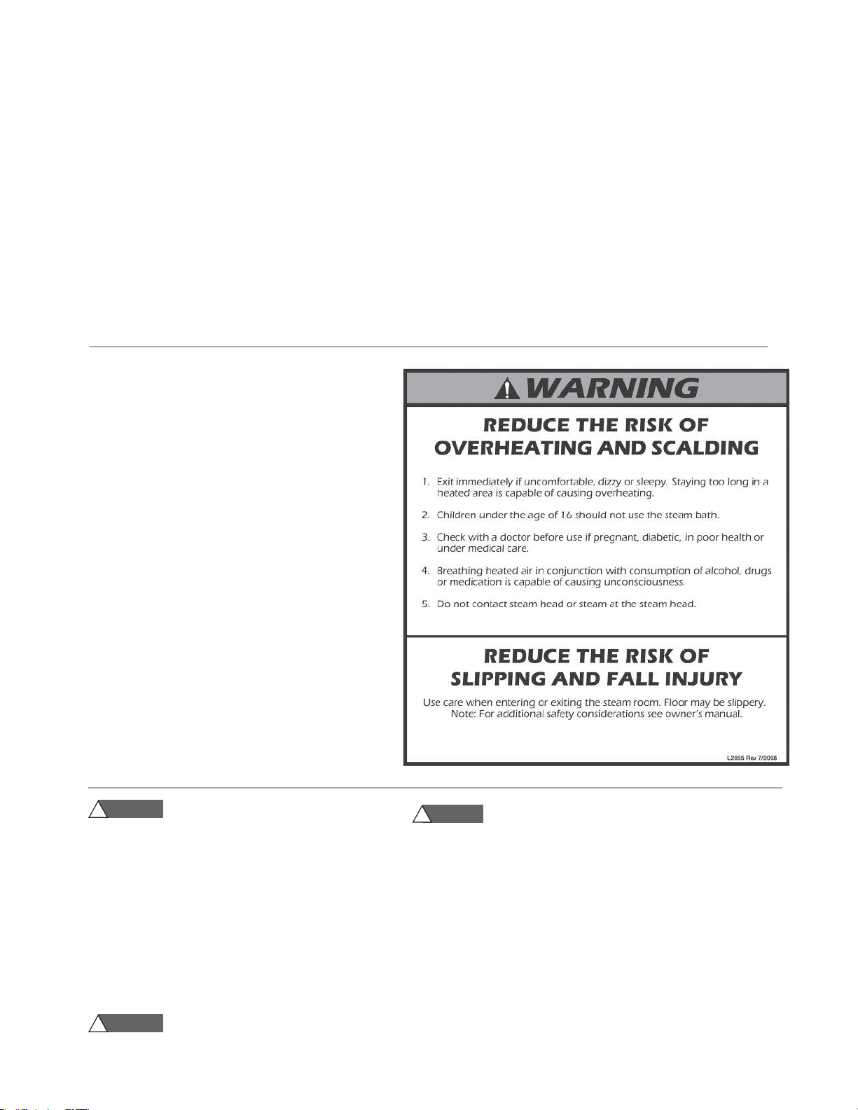
WARNING
!
WARNING
!
!
CAUTION
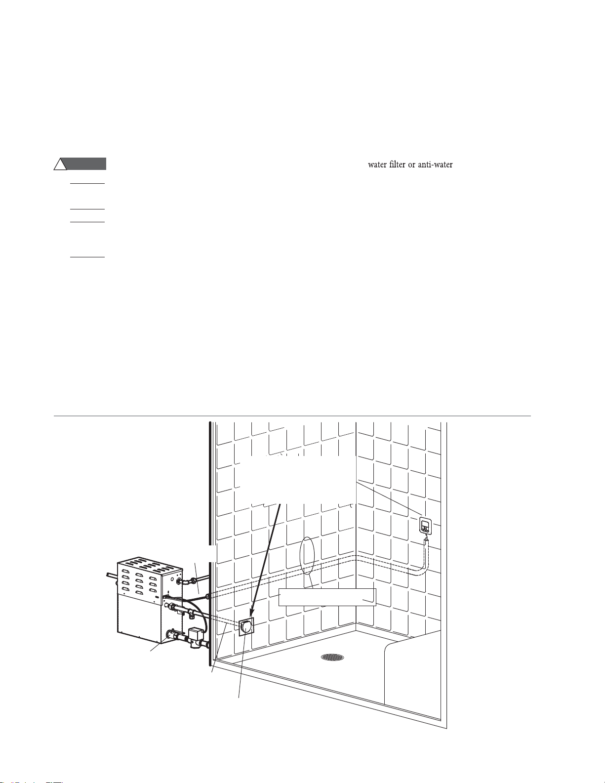
Ifacrylic,berglassorothernon-heatresistantmaterialsare
used as part of the steam room enclosure. Consult with the material
manu-facture and see pg. 6, “Installing the Steamhead"for additional
details.
IMPORTANT NOTES:
This document contains important safety, operation and maintenance
infor-mation. Leave this document with the club/spa management.
Do not discard this document.
The following general information should be used in conjunction with con-
sultations with an architect, designer and contractor in determining
factors necessary in providing asuitable and safe steam room.
"RVBTUFBN BSF JOUFOEFE UP CF PQFSBUFE XJUI / BOE BSF UP CF
JOTUBMMFE TUSJDUMZ JO BDDPSEBODF XJUI UIF TQFDJGJD JOTUSVDUJPOT DPOUBJOFE JO UIJT
NBOVBMBOEBTTVQQMJFEJOUIFNBOVBMTQSPWJEFEXJUIUIFDPOUSPMTPSBDDFTTPSJFT

4
(Items 1-7)
1. DO NOT install steambath generator or plumbing lines in
unheated attic or any locations where water could freeze.
2. DO NOT install steambath generator inside steam room.
3. DO NOT install steambath generator outdoors or wherever
environmental conditions may aect the safety and/or
performance of the generator.
4. DO NOT install steambath generator near ammable or corrosive
materials or chemicals such as gasoline, paint thinners, or the like.
Installation in areas having high concentrations of chlorine (such
as pool equipment room) must be avoided.
5. Install steambath generator on a solid and level surface. Keyhole
slots are provided for wall mounting. Insure the steam generator
is properly secured and level when mounting with keyhole slots.
6. Install steambath generator in an upright position only.
7.
Steam line, safety valve, drain valve, plumbing and steamheads
become hot during operation and remain hot after shutdown
for a period of time. Provide appropriate protection, including
insulating plumbing lines. Avoid plumbing runs and steamhead
locations that can come in contact with bathers.
NOTE: FOR ILLUSTRATIVE PURPOSES ONLY
Some components may be omitted or altered
for clarity. Do not use for wiring, repair or other
purposes not related to component identication
.
Provide unions as required to facilitate
installation and disconnect of piping
Steam
Generator
Field installed
power supply
Field installed
steam supply pipe
DrainValveshouldbeclosedJG
AutoFlushisnotinstalled
Controlcablesrunin1”conduit
(locatedbehindthewall)
Steam Head (shown with optional acrylic shield)
See page 6 for Steam Head Installation information
Field installed
water supply line
Typical Installation
IMPORTANT:
(Items 8-11)
8. Install hammer device as
necessary.
Provideaminimumof12inchesatbothendsand
topofthesteamgeneratororasrequiredforservic-
ing.Seepage7.
Provideunionsasrequiredtofacilitate
installationanddisconnectionofpiping.
WARNING
!
NOTE:
"RVBTUFBNGeneratorsandcontrolsareCE
andULlisted.
_________________________________________________________________________________________
LocatingtheSteamGeneratorUnit
IMPORTANTNOTE:
Thecontrolcablesshouldberunindedicated1"conduittofacilitateinstallationandservice
Selectalocationasnearaspracticaltothesteamroom.Typicallocationsinclude:closet,vanitycabinet,heatedatticorbasement.
NOTE:
ThemaximumlengthoftheN2762ȩis60feet.6TJOH PQUJPOBM DBCMF 4UBOEBSE JT GFFU *U DPOOFDUT UP
thesteamgenerator.
IMPORTANT:
Locatethe/
sensorinalocationrepresentativeofthe
desiredsteambathingtemperatures.Do
notlocatethecontrolaboveornearthe
steamheadordirectsteamemissions.
*
*.1035"/5

1. Install each steam generator as in a single installation. Install genera-
tors as close as practical to each other, not exceeding 10 feet.
The interconnecting cable length is 12 feet.
2. Shock Hazard. Power must be disconnect-
ed at the main electrical supply. Remove steam gen-
erator covers. Retain screws and covers for reuse.
Connectthe/Dontroltoeitherunitasperthe
InstallationManualsuppliedwitheachcontrol.
3FNPWFPOFLOPDLPVUPOFBDIHFOFSBUPSBTTIPXO
*OTFSUUIFFOETPGJOUFSDPOOFDUJOHDBCMFQSPWJEFE
UISPVHIUIFLOPDLPVUTBTTIPXOJOEJBHSBN
$POOFDUFBDIFOEUPUIFQSJOUFEDJSDVJUCPBSE
DPOOFDUPSMBCFMFE5"/%&.BTTIPXO
1SFWFOUUIFJOUFSDPOOFDUJOHDBCMFGSPNDPOUBDUJOH
IPUTVSGBDFTTVDIBTTUFBNPVUMFUTBGFUZWBMWFBOE
UIFMJLF
$POOFDUTFQBSBUFQMVNCJOHBOEQPXFSTVQQMJFTGPS
FBDIVOJU3FQMBDFDPWFSTXJUIDPWFSTDSFXT
1SPWJEFVOJPOTBTSFRVJSFEUPGBDJMJUBUFJOTUBMMBUJPO
BOEEJTDPOOFDUJPOPGQJQJOH
NOTE: The secondary unit will de-energize when the
steam room reaches steambathing temperature resulting
in a more gentle and energy efficient operation.
Printed Circuit Board Component
shown enlarged for illustrative purpose.
Primary Unit
Interconnecting
Cable
Control
Cable
Secondary Unit AutoFlush
®
, see AutoFlush
Installation page 14
Steam Heads
Water Feed
Line
Power
Supply
_________________________________________________________________________________________
8IFOUIFDBMDVMBUFETUFBNSPPNWPMVNFFYDFFETDVCJDGFFUUIFHFOFSBUPSDBOCFDPNCJOFE
TYPICALINSTALLATIONINSTRUCTIONS
!
WARNING
/ DVCJDGFFU
/ DVCJDGFFU
/ DVCJDGFFU
3PPNWPMVNFVQUP

Installation
Plumbing
All plumbing shall be performed by a qualified licensed plumber
and in accordance with applicable National and local codes.
• Use unions on all pipe connections.
• Use only brass piping or rigid copper tubing as permitted
by codes.
• Do not use black, galvanized, PVC, or PEX pipe.
Water Supply (3⁄8"NPT)
Connecttocoldwaterline.
Provideashutoffvalveinthewatersupplylineupstreamofthe
steambathgenerator.
Donotoverheatinletsolenoidvalvewithsolderconnections.
Overheatingwilldamageparts.
Flushinletwaterlinethoroughlybeforemakingconnectionto
unit.
Strainerrecommendedupstreamoffeedwaterconnection.
Forbestperformancewaterpressureshouldbe15to20psig.
Reducepressureasrequired.
ProvideXBUFSGJMUFSBOEPSBnti-waterhammerdeviceas
required.
Installanapprovedbackflowpreventerasrequiredbylocal
codes
.b
Drain
(1"NPT)
Thedrainfromthegeneratorshouldnotshareanundersink
trap,unlessthegeneratorismountedhigherthanthesink.
NOTE:Adrainvalveisprovidedtofacilitateservicing.
Provideadrainlineconnectionfromsteambathgeneratordrain
valveaccordingtoNationalandlocalCodes.Checklocalplumbing
codeforreceptor,trapandventrequirements.Donotconnect
DrainlineandSafetyValvelinetogether.Unitdrainsbygravity.
DoNOTconnectthedrainvalvetothesteamline.
SafetyValve
(3⁄4"
NPT
)
Wherepermittedbylocalcodes,provideanoutletplumbingcon-
nectionforsafetyvalve.
To insure proper and automatic safety valve
operation: DO NOT connect a shut off valve or a plug at
safety valve outlet. DO NOT connect a shut off valve or any
construction in steam supply pipe.
Steam Outlet (1⁄2"NPT)
1. Do not install any valve in steam line. Flow of steam must
be unobstructed.
2. Use 1⁄2inch brass pipe or copper tubing from unit to
steam head as permitted by codes.
3. Insulate steam line with fiberglass pipe insulation or similar
insulation rated 212° F or higher.
4. Pitch steam line 1⁄4" per foot towards steam head or steam
generator to avoid valleys and trapping of condensate.
IMPORTANT NOTES:
• Running the steam line down and then up will create a
steam trap blocking the flow of steam.
•
A 1.5" hole in the steam room is required to mount the
steamhead.
Water Quality Information
For optimum results, the water supply should be tested prior
to installation. If the mineral content exceeds the following
recommended limits, various external treatment processes are
recommended to correct the problem.
NOTE: An analysis of the on-site water must be made by a
recognized and reliable water treatment company to ascertain
the existing condition and treatment required.
Poor water quality can affect efficiency or result in steam gen-
erator damage. Water contains impurities in solution and sus-
pension. These impurities concentrate in the generator. The
concentration of these impurities increases as more feedwater
is introduced into the generator and steam is produced. If the
suspended solids are allowed to concentrate beyond certain
limits, a deposit or “scale” will form on the generator internal
surfaces.Thisdepositcaninterferewiththepropergenerator
operationandcausegeneratorfailure.Theconcentrationof
theseimpuritiesisgenerallycontrolledbythewaterquality
andbyperiodicdrainingofthegenerator.
RECOMMENDEDFEEDWATERQUALITY
Hardness,ppm8–85(~0.5–5gpg)
P-Alkalinity,ppm85–
410(~5–24gpg)
T. Alkalinity,ppm200–500(~7–0gpg)
pH(strengthofalkalinity)8.0–11.4
4HEȩ!UTO&LUSHLjȩ3YSTEMȩFEATUREȩAUTOMATICALLYȩDRAINSȩTHEȩ
!QUASTEAMȩGENERATORȩFOLLOWINGȩEACHȩUSEȩ!ȩTIMEȩDELAYȩ
ALLOWSȩTHEȩWATERȩTOȩCOOLȩDOWNȩABOUTȩTWOȩHOURSȩBEFOREȩITȩ
DRAINSȩBYȩGRAVITYȩFORȩAȩSAFEȩANDȩGENTLEȩOPERATION
WARNING
!
_________________________________________________________________________________________

Steam
Supply Pipe
End of pipe to
be recessed 1/8"
1/8" minimum clearance
required for
Acrylic Shield.
Apply with silicone
or equal sealant
as required for
moisture seal.
UseTeflon® or
equal sealant on
pipe threads
NOTE: A1
1⁄2
" clearance hole around the steam pipe is
needed to mount the steamhead.
STEP 1
Locate steam head 6-12 inches above oor, except for:
1. Tub/shower enclosures, install 6 inches above tub top edge.
2.
3.
Consultwithsupplierofacrylic,berglassandothernon-heat
resistantenclosuresforrecommendedsteamheadlocation.
UseAcrylicShieldinstructionsprovidedwithsteamshield.
STEP
SecureabronzedropearfittingtoaheaderandrunB
1
⁄
2
"copper
steamlinefromthesteamgeneratortothedropearfitting.Install
atemporarynipple(6"orlonger)inthedropearfittingtolocate
thesteamheadafterthewallisfinished.
STEP
Afterthewallhasbeenfinished,markonthenipplewherethe
surfaceofthewallis.Removethenippleandmeasuretheportion
thatwasinthewall(theendtoyourmark).Subtract1⁄8"fromthat
dimensionandselectabrassnippleofthatlengthtofinishthe
installation.
STEP
Wrapteflontapearoundthethreadsofthenewnippleandscrewthe
nippleintothesteamhead.Donotusewrenchesortoolswhich
woulddamagethesteamhead'sfinish.
Wrapteflontapearoundthethreadsofthenippleandscrewthe
nippleandsteamheadassemblyyoujustmadeintothedropearfit-
tinginthewall.Thesteamheadshouldbeflushwiththewallandthe
wellmustbefacingup.
__________________________________________________________
IMPORTANTNOTE:
•
•
Do not disassemble steamhead , steamhead is shipped fully
assembled and requires no additional assembly.
To preserve steam head nish, do not use wrenches or other
tools to tighten. DO NOT use abrasive cleansers or chemicals.
Use only water with mild soap and anon-abrasive sponge.
Because the steam head and direct steam emissions are very hot,
locate the steam head where incidental contact by bather with
the steam head or direct steam emission cannot occur.
STEP
STEP
STEP
Installing the AromaSteam Steamhead (1⁄2" NPT)
Steamhead
Locating Nipple
Drop Ear
Fitting
CAUTION
!
All drawings are for illustrative purposes only
_________________________________________________________________________________________
Oil Well

17"
(432)
2
3/8
"
(60)
23/8"
(60)
71/4"
(184)
121/2"
(310)
13/4"
(45)
183/4"
(466)
4"(102)
6"(152)
97/8"
(251)
13/8"
(35)
63/8"
(162)
12”(305)
for servicing
WATER INLET 3/8” NPT
STEAM OUTLET 1/2” NPT
SAFETY VALVE 3/4” NPT
MANUALDRAINVALVE1”NPT
AUTOFLUSH VALVE 1”NPT
77/8"(200)
NOTE
:
"llunitsininches(MM
Water Inlet
Steam Outlet
Safety Valve
AutoFlush
Manual
Drain Valve
Side View
Showing Element
Access Panel
Generator Dimensions
IMPORTANT NOTES:
• Provide a minimum of 12 inches at both ends and top
of the steam generator or as required for servicing.
Alternately, provide unions as required to facilitate
installation and disconnection of the steam generator.
• The minimum clearance from combustible surfaces is
zero all around.
TO AVOID EQUIPMENT DAMAGE DO NOT CONNECT
POWER SUPPLY DIRECTLY TO ELEMENTS !!!
All drawings are for illustrative purposes only
Water Inlet
Control &
Accessory
Connections
Steam Outlet
Safety Valve
Manual
Drain Valve
_________________________________________________________________________________________
/

Transformer
Liquid Level
Control Board
Water Feed
Solenoid
Water Feed
Thermostat
Liquid Level Probe
Power Block
Power Supply
Knock-Out
Contactor
Steam Outlet
Fuses
AutoFlushPlugand
PlayConnector
(seepage1)
_________________________________________________________________________________________
Field Power Wiring
1. TO AVOID EQUIPMENT DAMAGE DO
NOT CONNECT POWER SUPPLY
DIRECTLY TO ELEMENTS!!!
2. L1, L2, Ground to be field wired
Models.ȩȩ.
(singlephasewiring)
Model.
(singlephasewiringshown)
Electrical
All electrical wiring to be installed by a qualified licensed elec-
trician in accordance with National Electrical Code and local
electrical code.
Power Wiring-
See “Field Power Wiring” Diagrams (below)
usetwo-wiresupplysourceandequip-
mentgroundingwire.Neutral(white)wireisnotrequired.
!
WARNING
Provideapowersupplydisconnectwithinsightofthesteam
generatororonethatiscapableofbeinglockedintheopenpositionaspermittedbycode.d
NOTE: FOR ILLUSTRATIVE
PURPOSES ONLY
Some components may be omitted
or altered for clarity. Do not use for
wiring, repair or other purposes not
related to component identification.
______________________________________________________________
Amper
____________________________________________________________
e Chart __
Maximum Room Voltage/ Wire Size
pha
______
se
______________
Model N
___________________
o. Volume ft
3
(m
2
)KW
________________
Amperes
________________________________
AWG ( mm
2)
__
ABSC02787 225(6.37) 7.5
_____________________________________________________________________
240/1 32 8 (10 )
ABSC02789 360 (10.19) 9.0
__________________________________________________________________________
240/1 38 8 (10 )
ABSC02782 575 (16.82) 12
_________________________________________________________________________
240/1 50 6 (16)
Transformer
Liquid Level
Control Board
Water Feed
Solenoid
Steam Outlet
Liquid
Level Probe
AutoFlush
®
Plug and
Play Connection
(see page 14)
Contactor
Power Supply
Knock-Out
Field
Wiring
Water Feed
!
CAUTION
!

_________________________________________________________________________________________
CONTACTOR
To Probe
HEATING ELEMENT
MSTS
TEMP. PROBE
AutoFlush
CT-SteamStop
/
/
Control
Transformer
POWER INPUT
L1 L2
GROUND
Express
Steam
WATER
FEED
SOLENOID
VALVE
THERMOSTAT
THERMOSTAT
HEATER
FACTORY
WIRING
FIELD
WIRING
LEGEND
(All Diagrams)
CONTROL BOARD
CONTACTOR
Heating Element To Probe
AutoFlush
CT-SteamStop
/
Control
TRANSFORMER
POWER INPUT
L1 L2
FUSES
GROUND
WATER
FEED
SOLENOID
VALVE
Express
Steam
THERMOSTAT
HEATER
Single Phase
Wiring Diagrams
MODEL
..
MODEL.

1
Initial Start-Up and Checkout
Turnoncontrol.Followspecificinstructionsprovided
withcontrols.
Steamwillbegintoappearinapproximatelymin-
utesatthesteamhead.Steamwillshutoffwhen
desiredtemperatureisreachedandwillautomatically
resumewhenroomtemperaturedropsbelowset
point.
Toshutsteamoffmanually,turncon-trolOFF.To
clearsteamfromenclosurearea,turnshoweron
beforeopeningdoor.
IfunitdoesnotstartandcontroldoesnotturnON
(controldisplaydoesnotlightup)thenturnbreaker
offfor20secondsandtryagain.
Refertospecificinstructionsheetsforinstallation,
operationandmaintenanceofoptionalequipment
andControlb
Maintenance
"RVBTUFBNsteambathgeneratorsrequirelittlemaintenance.3INCEȩ
ITȩFEATURESȩTHEȩ"UTO'LUSHȩSYSTEM
Otherthandraining,maintenanceproceduresareminimal.When
AutoFlushisnotinstalledthemanualdrainvalveshouldbeopened
fullyflushingoutaccumulatedmaterials,saltsandotherparticles
whicharenaturalby-productsofboilingwater,aftereachuse.
!
CAUTION
7ITHȩ!UTOFLUSHȩTHEȩUNITȩWILLȩDRAINȩAFTERȩȩHOURS
!
WARNING
$rainingimmediatelyafterasteamcyclemay
exposePVCandotherpipingtohightemperaturewater.
SteamGeneratorOperation
"RVBCSBTTSFcommendsbeginningsteambathingatalowtemperature
settingtogaugecomfortandsafetylevels.
_________________________________________________________________________________________

1
RED (Heater)
YELLOW (Water Level)
GREEN (Power)
Force On
Test Button
_________________________________________________________________________________________
SystemStatusCodes
The.controlmaydisplayastatuscodeifthesteamgeneratorisnotfunctioningproperly.
Code Code Meaning Probable Cause Suggested Remedy
H20 Water level is not Water Supply is off Turn on Water Supply
satisfied within 5 min. Defective water feed solenoid Check/replace water solenoid valve
Water feed probe not functioning Check/clean probe.
Check probe wiring.
Drain Valve Open Check/Close drain valve
AutoFlush not functioning Check/Replace AutoFlush
Prr1 Temperature Probe Error Control/Remote sensor cable cut Replace Control Cable/Sensor
or Prr2 Internal problem with control/Remote Sensor Replace ControlSensor
Err1 Incorrect Field Supply Voltage Incorrect voltage supplied Supply steam generator with the correct
(green light on liquid level to Generator voltage noted on the data plate label.
control board will be off)
Err2 Button on control is pressed Control cover misalignment Remove and reinstall control cover
for more than 5 minutes Debris behind control cover Remove control cover and clean cover,
control and keypad with a damp cloth
Err7 Liquid Level Control Board Memory error in LLCB Press ON/OFF to clear.
malfunction Replace control if code remains.
Liquid Level Control Board -
EXPLANATION OF LED INDICATORS
_____________________________________________________________________________________________________________________________________________
GREEN LED is ON when there is 208/240 Volt incoming power connected,
24 Volt transformer secondary output and on-board 5 Volt DC control power are present.
_____________________________________________________________________________________________________________________________________________
YELLOW Water level indicator–LED is OFF when no water is detected (for more that 5 seconds). ON when
water level is satisfactory. For units with AutoFlush, if more than five hours have elapsed since
last usage and this LED is ON it is indicative of an AutoFlush or water level probe circuit malfunction.
_____________________________________________________________________________________________________________________________________________
RED Contactor relay indicator–LED is ON when relay is closed and sending 24 Volts to the
contactor coil. (This LED comes ON if the generator is ON.)
_____________________________________________________________________________________________________________________________________________
FORCE ON This button is for trouble shooting only and will operate if a control is connected or not.
TEST BUTTON Pressing the button again will shut the generator OFF.
The test button will only allow the generator to operate for 10 minutes.
_____________________________________________________________________________________________________________________________________________
Liquid Level Control Board
PN 103975
(shown without wiring)

TROUBLESHOOTING
Step 1 Check main incoming power to the unit.
Step 2 Ensure the black wires from the pri-
mary side of the transformer are connected
to the quick connect tabs on the line side
of the contactor.
Step 3 Verify that you have 24VAC
coming out of the transformer, WHT &
WHT/BLU wires, into the board.
Step 4 Verify that you have the
green light on the PC board.
Step 5 Push the white test button to
run the generator for 10 minute test
cycle. Make sure the steam room is
empty.
Step 6 Verify that you have 24 VAC to the water feed
solenoid, GRY & WHT/GRY wires (will fill when needed).
Step 7 Temporarily short out the WLS (Purple wire) and
GND (Green wire) terminals and verify the contactor
engages.
Step 8 When the red light is on, verify 24 VAC,
RED & WHT/RED wires, to the contactor.
Step 9 Check main voltage on the
load side of the contactor when it is engaged.
Step 10 If all steps on the power path were verified, turn
off power to the unit and pull the heating element via
the left hand access panel for inspection.
DO NOT disassemble internal components,
All drawings are for illustrative purposes only
internal components contain no serviceable parts.
1
All electrical troubleshooting to be performed by a qualified licensed electrician
12
4
7
8
9
3
6
5
Transformer
Liquid Level
Control Board
Water Feed
Solenoid
Ste
Ou
Liquid
Level Probe
AutoFlush
and Play
Connectio
Contactor
Power Supply
Knock-Out Field Wiring
Water Feed
WARNING
!

_________________________________________________________________________________________
1
AutoFlush®
Box Contents
• AutoFlush Valve with Cord
• Installation instructions.
Operation
TheAutoFlushSystemfeatureautomatically
drainsthesystemfollowingeachuse.
Atimedelayallowsthewatertocooldown
(abouttwohours)beforeitdrainsbygravityfora
safeandgentleoperation.Unitdrainsbygravity.
InstallationInstructions
1. Plumbingtobeperformedbyaqualified
plumberandshallbeinaccordancewith
applicablenationalandlocalcodes.Unitdrains
bygravity.Adrainlinethatislowerthanthe
AutoFlushassemblymustbeavailable.The
AutoFlushSystemvalveoutletis1"NPT.Check
plumbingcodeforreceptor,trapandventrequirements.
3. Open Drain Valve (handle must be aligned with brass nipple).
4. Connect the AutoFlush System cord connector to
the three pin connector as shown.
Drain Valve
DO NOT TURN OR REMOVE
THE DRAIN VALVE
(shown in the correct open position)
Steam Generator
Nipple Plumb to
Drain Line
AutoFlush Valve
AutoFlush Cord
AutoFlush Valve
3 Pin Connector
for AutoFlush
AutoFlush Cord Connector
Drain Valve
(shown in the correct open position)
DO NOT REMOVE THIS DRAIN VALVE
Steam Generator
Nipple
copper or brass
nipple 1" NPT x
31⁄2"or longer
(not supplied)
Plumb to
Drain Line
Arrow indicates correct
direction of flow
!
WARNING
Donotdrainintoasteamenclosureorany
locationwhereaccidentalcontactwithdrainwatermayoccur.In
theeventofapowerfailuretheAutoFlushSystemvalvewill
openandmaydischargeboilingwater.
SweatFittings
Whenusingsweatfittingsuseonlytinbasesolderwithamelt-
ingpointbelow600degreesF. Donotoverheat.Endsofwater
supplytubingmustbethoroughlycleanforaminimumdistance
of1"fromends.Donotremovevalvecover.
ToCheckOperation
Turnon"RVBTUFBNandallowtanktofillwithwater.
Turnoff"RVBTUFBNcontrol.Watershouldstayin
tank.
Turnoffpoweratthepanelbox.Watershould
dischargefromtank.
Turnonpoweratpanelbox.
RepeaUb
Usecopperorbrassnipple1"NPTx3
1
⁄
2
"orlonger
(notsupplied)toconnectAutoFlushvalvetotheDrainValve,
CAUTION
DONOTREMOVETHEDRAINVALVERemoval
maycauseequipmentandpropertydamage.
Ifthereisnotenoughroomforthevalve,anelbowand
ashortnipple(notprovided)canbeaddedb
CAUTION
!
PROVIDE DRAIN PLUMBING ACCORDING
TO LOCAL CODES. PLUMB AS REQUIRED
FOR AUTOFLUSH SYSTEM.
notingthedirectionofflowontheWalvebody.
!

1
_________________________________________________________________________________________
Replacement Parts List
____________________________________________________________
Part No. Description Product
____________________________________________________________
99178CT Drain Valve All models
99297 Safety Valve 15PSI All models
100479 Water Feed Solenoid All models
Valve w/filter
10477-3 Transformer 24VAC All models
103975 Liquid Level Control Board All models
100476-2 Contactor 50A 2-pole //
Single phase
103453 Contactor 50A 4-pole .
100471-2 Probe Assembly All models
99096MS Heating Element Gasket All models
103412 Acrylic Shield All Models
99314 Power Fuse 60A 250V
2901CMS HeatingElementKW240V /
29#MS HeatingElementKW2V/
29121CMS Heating Element 12 KW 240V /
104016 Thermostat All models
.

Transformer
Drain Line
Liquid Level
Control Board
Fuses
Water Inlet
Water Feed
Solenoid
Safety Valve
AutoFlush
Valve
Stainless
Steel Tank
Heating
Element
Access Cover
Thermostat
Liquid Level Probe
AutoFlushPlugand
PlayConnector
(seepage1)
Power Block
Power Supply
Knock-Out
Steam Outlet
Contactor
.PEFMT
/
/
/
shownwithcoverremoved
NOTE: FOR ILLUSTRATIVE
PURPOSES ONLY.
Some components may be
omitted or altered for clarity.
Do not use for wiring, repair
or other purposes not related to
component identification.
.PEFMT
/
/
shownwithcoverremoved
NOTE: FOR ILLUSTRATIVE
PURPOSES ONLY.
Some components may be omitted
or altered for clarity. Do not use for
wiring, repair or other purposes not
related to component identification.
1
_________________________________________________________________________________________
Transformer
Nipple
(not included)
Liquid Level
Control Board
Water Feed
Solenoid
Water Inlet
Safety Valve
AutoFlush
Valve
(optional)
Stainless Steel Tank
Heating Element
Access Cover
Liquid Level Probe
Plug and Play
Connection (see page 13)
Contactor
Power Supply
Knock-Out
Steam Outlet
Express Steam
Heater (optional)
Manual
Drain Valve

1
Care Tips for all Controls and Steamheads
1. Use only mild soap and water on a soft cloth to
clean the control and steamhead.
2. Do not use abrasive cleansers.
3. If the decorative cover is damaged on the
iTempo/ Plus call Mr.Steam technical service for
replacement parts.
NOTE: Replacement of the decorative covers
requires removal and reinstallation of the control
from the mounting surfaces.
_________________________________________________________________________________________

aquabrass.com
last revision: 10/20/2016
Aquasteam N2787/N2789/N2782
steambath generator 7.5KW 9KW 12KW
générateur de vapeur 7.5KW 9KW 12KW
Care
Entretien
To clean your Aquabrass faucet or accessory, wash with a wet nonabrasive soapy cloth. Then wipe dry with a soft towel or cloth. We
recommend this be done on a regular basis.
DO NOT USE ANY ABRASIVE, CHEMICAL OR CORROSIVE, POWDER OR ANY OTHER STRONG CLEANERS INCLUDING DETERGENTS,
WINDOW CLEANERS AND DISINFECTANTS ON YOUR Aquabrass PRODUCT as they will destroy the finish and therefore VOID THE
WARRANTY.
Toothpaste remnants should also be rinsed off when necessary. Ask your plumbing retailer about our PROTECTANT-CLEANER now
available from Aquabrass. This product is specially manufactured to clean and polish leaving a protective coating to maintain your
product’s shine and finish.
Pour nettoyer et conserver l’apparence de vos robinets ou accesoires Aquabrass, lavez-les avec un linge mouillé à l’eau tiède et
enduit d’un savon doux non-abrasif. Puis essuyer avec un linge doux et sec. Nous vous recommandons cet entretien sur une base
régulière.
NE JAMAIS UTILISER DE PRODUITS ABRASIFS, CHIMIQUES, CORROSIFS, INCLUANT DE TRÈS FORTS DÉTERGENTS, EN LIQUIDE OU EN
POUDRE, NETTOYANTS POUR VITRES ET DÉSINFECTANTS sur votre produit Aquabrass. Cela pourrait en détériorer le fini et ANNULER
LA GARANTIE.
Les restants de pâte à dentifrice doivent aussi être rincés au besoin. Demander à votre détaillant le PROTECTEUR NETTOYANT
Aquabrass spécialement conçu pour nettoyer, faire briller et protéger en laissant un mince film protecteur sur vos robinets et vos
articles décoratifs.
This manual suits for next models
2
Table of contents
Popular Portable Generator manuals by other brands

Pramac
Pramac P2200i Operator's manual

Scheppach
Scheppach SG3200x Translation of original instruction manual

iTechworld
iTechworld AU4i user manual

Troy-Bilt
Troy-Bilt 01919-1 owner's manual

Champion Power Equipment
Champion Power Equipment CSA40025 Owner's Manual and Operating Instructions

Westerbeke
Westerbeke 22.0 KW EDE-60Hz Service manual