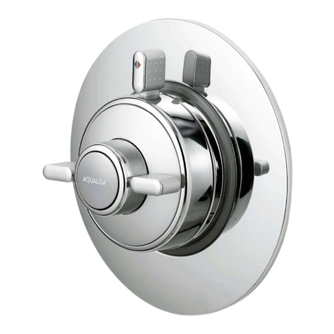
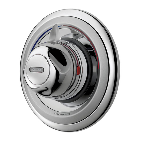
Aqualisa Aquatique Thermo Series User manual

Aquatique Thermo installation instuctions page 2
Sho er systems
Aquatique Thermo
Exposed valve
Chrome
500.10.01
Gold
500.10.04
Aquatique Thermo
Con ealed valve
Chrome
500.00.01
Gold
500.00.04

Aquatique Thermo installation instuctions page 3
Components
Exposed
Con ealed
Literature not shown
Literature not shown

Aquatique Thermo installation instuctions page 4
Important information
Introdu tion
The Aquatique Thermo is an antique style brass bodied thermostatic shower valve designed for built in and concealed panel
mount and exposed installations.
The Aquatique Thermo provides close temperature stability and fail safe protection when installed on approved gravity or
pumped systems and balanced high pressure systems. A cold inlet flow regulator is provided for use with instantaneous
(multipoint) gas water heater and combination boiler applications.
Flexible and 5” and 8” drencher heads are available to complement the Aquatique Thermo valves, dependent on your water
system, and should be purchased separately.
If you have any questions at any stage during installation please contact the Aqualisa customer helpline on 01959 560010 for advice.
Safety information
This product must be installed by a competent person in accordance with all relevant current Water Supply Regulations.
Flushing
Some modern fluxes can be extremely corrosive and, if left in contact, will attack the working parts of this unit. All soldering
must be completed and the pipe work thoroughly flushed out in accordance with Water Supply Regulations prior to connection
of the product.
Conne tions
The Aquatique Thermo is supplied for connection to conventional supplies with HOT on the LEFT and COLD on the RIGHT
when viewed from the front. However, the valve can be adapted for use with non-conventional supplies by rotating the valve
body by 180˚. Please see installation instructions overleaf to reverse the valve.
The Aquatique Thermo exposed valve is supplied complete with 15mm compression elbow fittings at 198mm centres. The
Aquatique Thermo concealed valve is NOT supplied with any elbow connections. Suitable ‹÷¢” BSP union connections will be required.
Pipe work connections to this product should be cut using a rotary type cutter.
Isolating valves
Suitable isolation valves such as gate valves must be fitted to both supplies in accordance with the Water Supply Regulations
and our terms of warranty. Due to their restrictive characteristics, stopcocks and ball type valves that reduce the pipe bore size
must not be used on gravity or gravity pumped installations.
Filters
To ensure ongoing optimum performance the internal control mechanism ‘cartridge’
is protected by a two-part filter system. Debris accumulation may result in reduced flow
from the shower head and noisy operation.
As this condition is not covered by our standard warranty terms, it is suggested that the
cartridge be removed and the filters checked by a competent person. In the event of
any difficulties please contact the Aqualisa customer helpline for assistance.
Siting
For optimum performance, with gravity fed systems the distance between the bottom of the storage cistern and the shower
head should not be less than 1m (when using an adjustable shower kit). If using a fixed head, the highest point of the pipe
work must be not less than 1m below the underside of the cistern. Please refer to the system layouts on the reverse of this guide.
Pump installation
UNDER NO CIRCU STANCES UST A PU P BE FITTED DIRECTLY TO THE WATER AIN
A pump must only be used to boost the pressure from tank-fed supplies. A typical
layout is shown on the reverse of this guide.

Aquatique Thermo installation instuctions page 5
Important information
Stored water apa ities
The minimum capacity of the cold storage cistern should be less than 225 litres (50 gallons). The capacity of the hot cylinder
must be capable of meeting the anticipated demand.
Pressures
The Aquatique Thermo valve is designed to control static pressure up to 10 bar. Where pressures are likely to exceed 10 bar a
pressure reducing valve (PRV) must be fitted into the incoming mains supply. A setting of 3 bar is recommended. It should
be noted that daytime pressures approaching 8 bar can rise above the stated maximum overnight.
A suitable PRV is available from Aqualisa.
Gravity fed hot and old supplies
Services must be installed according to good plumbing practice having regard to pipe sizing, long pipe runs and low-head situations.
The cold supply for the valve assembly must be taken directly from the cold water storage system. The hot supply may be
taken from the vent/draw off pipe of the hot water cylinder at a point below the cylinder connection or alternatively from the
underside of the horizontal draw off.
Rising pipe work must not be connected into the horizontal draw-off from the cylinder or to any point in the vent/draw off pipe
above the cylinder connection.
CYLINDER TE PERATURE IN EXCESS OF 65˚C AY RESULT IN POOR SHOWER PERFOR ANCE
To minimise pressure loss we recommend that the hot and cold supplies are run in 22mm as close as is reasonably possible to
the mixing valve before reducing to 15mm.
Balan ed high-pressure system
The Aquatique Thermo cartridge is designed to operate with unvented hot water storage systems up to a maximum pressure
of 10 bar. A PRV must be used if either supply exceeds 10 bar. The cold water supply must be drawn from the same mains sup-
ply as that to the hot water system (down stream of the cylinder manufacturers pressure limiting valve, where supplied) and
the hot supply from the nearest convenient draw-off point. Account must be taken of pressure drops that may occur when
other draw-off points are used while the shower is in use. Pipe work can generally be run in 15mm.
A typical layout is shown on the reverse of this guide.
Combination boiler/multipoint system
The gas water heater must be capable of raising the temperature of the incoming water by 35˚C and delivering a flow rate of
no less than 9 litres (2 gallons) per minute to the shower valve. This is sufficient to operate one outlet point at a time.
The Aqualisa Thermo cartridge is designed to operate from the mains at a maximum pressure of 10 bar. If the mains pressure
exceeds 10 bar a ‘drop tight’ PRV must be fitted on the supply pipe after the main stopcock.
The cold supply can be taken from the nearest convenient mains supply and the hot supply can be taken from the nearest
hot water draw-off point. Account must be taken of the pressure drops that will occur when other draw-off points are used
while the shower is in use. Pipe work can generally be run in 15mm.
A typical layout is shown on the reverse of this guide.
Complementary shower heads
Various shower heads are available to complement the Aquatique Thermo unit, which are available separately. Please select
from the following options:
Option 1. Adjustable height kit. Choose from adjustable height kit concealed or exposed (compatible with any water system).
Option 2. 5” drencher head. Choose from exposed or concealed (compatible with most water systems – the flow switch on
combination boilers should be capable of passing a minimum of 12 litres per minute at 55ºC. If in any doubt, please contact
the appliance manufacturer before installation commences.
Option 3. 8” drencher head. Choose from exposed or concealed (compatible with high pressure or boosted systems only).
Please refer to the installation guides supplied with the shower heads for full fitting instructions.
If you have any questions regarding the specification of compatible shower heads please contact the Aqualisa customer
helpline on 01959 560010 for advice.

Aquatique Thermo installation instuctions page 6
Step -by-step instructions
In addition to the guide below it is essential that the written instructions
overleaf are read and understood and that you have all the necessary
components (shown overleaf) before commencing installation. Failure to
install the product in accordance with these instructions may adversely
affect the warranty terms and conditions. Do not undertake any part of this
installation unless you are competent to do so. Prior to starting ensure that
you are familiar with the necessary plumbing regulations required to install
the product correctly and safely.
Aquatique Thermo is supplied with universal fittings.
Please note that the fixing template is supplied as a guide only, we thus
recommend that you assemble the valve and measure the pipe inlet
centres against the template prior to installation.
Carefully cut out the cardboard fixing
template supplied, mark out the inlet supply
holes at 194mm centres.
1
Rear entry pipe work
Set the pipe work to emerge from the wall at right angles.
2
ake good the wall as appropriate. After making good, measure the pipes
and mark the pipe cut off length (19mm-21mm).
3
Remove the mounting ring from the rear of the valve using the 2.5mm
hexagonal key provided. Locate the ring inside the large ring on the template
ensuring the locking screw is in the 6 o’clock position and mark the four
fixing holes.
4
!
!

Aquatique Thermo installation instuctions page 7
Remove the fixing template. Using a rotary type cutter cut the inlet pipes to
length and drill and prepare the fixings for the mounting ring.
Fix the mounting ring to the wall using the screws provided.
5
Briefly run the hot and cold supplies to flush out any debris that may be
present in the system.
6
If the valve is being installed for use with a gas fired instantaneous
(multipoint) water heater or a combination boiler, the cold water flow
regulator must be fitted at this stage by insertion into the cold inlet
connection ensuring the small ‘O’ ring is facing the incoming flow,
prior to connection of the elbow assemblies.
7
Carefully slide the cover plates onto the
elbows to cover the compression fittings.
8
Place the assembly into the mounting ring
and onto the supply pipes. Tighten the
locking screw to secure the assembly to the
mounting ring using the 2.5mm hexagonal
key provided.
11
Carefully slide the dummy nuts onto the
elbows ensuring damage to the plated
surfaces is avoided.
9
Carefully locate the elbows into the valve
inlet connections and push fully home.
Using the 2.5mm hexagonal key provided,
tighten the locking screw enough to retain
the elbows in the connections whilst still
allowing ease of movement for final
adjustment.
10

Aquatique Thermo installation instuctions page 8
Carefully cut out the cardboard fixing
template provided, mark out the position
of the mouting ring. If required the
(194mm) inlet pipe centres may be used as
a guide to mark out the falling or rising
exposed pipework as appropriate to aid the
positioning of the pipe fixing clip locations.
1
Surfa e sited pipe work
Tighten the elbow locking screws using
2.5mm key provided. Slide the dummy nuts
into position and rotate them so the locking
screw is out of site before securing them
using the 2.5mm key.
Remove the mounting ring from the rear of
the valve using the 2.5mm hexagonal key
provided. Locate the ring inside the pre
marked position, ensuring the locking screw
is in the 6 o’clock position and mark the four
fixing holes.
2
Drill and prepare the fixings for the
mounting ring. Fix the mounting ring to the
wall using the screws provided.
3
Follow steps 6 to 13 listed above.
4
Tighten the inlet compression unions sufficiently to ensure a watertight seal.
Push the cover plates over the unions flush to the wall surface.
12
13

Aquatique Thermo installation instuctions page 9
In addition to the guide below it is essential that the written instructions
overleaf are read and understood and that you have all the necessary
components (shown overleaf) before commencing installation. Failure to
install the product in accordance with these instructions may adversely affect
the warranty terms and conditions. Do not undertake any part of this
installation unless you are competent to do so. Prior to starting ensure that
you are familiar with the necessary plumbing regulations required to install
the product correctly and safely.
Aquatique Thermo is supplied with universal fittings.
Elbow connections are not supplied with concealed models; suitable ‹÷¢” BSP
unions are required.
!
Con ealed valve
If installing the product built in to a solid wall, chase out a suitable recess in
the wall to receive the valve and pipe work. If installing the valve in a
concealed panel mounted situation, in most cases it will be necessary to first
install a suitable sound fixing in the cavity area before fixing the valve.
A hole of Ø130mm is required to install the valve and gain access to inlet
and outlet connectors.
1
inimum mounting depth 68mm,
maximum depth 82mm, measured
from mounting surface to
finished/tiled wall surface.
!
Set the temperature lever to the vertical
position, undo the four screws and remove
the temperature lever and on/off control
assembly.
2
Remove the mounting ring from the shower valve using the 2.5mm
key provided.
3
Position the mounting ring in the chase or
suitable sound fixing surface. Ensure the
locking screw is in the 6 o’clock position and
mark the four fixing holes. Prepare the holes
and secure the mounting plate to the wall
using the fixings provided.
4
!
in 68mm
ax 82mm

Aquatique Thermo installation instuctions page 10
Insert the valve into the mounting ring and
tighten the locking screw using the 2.5mm key
provided.
5
Using suitable ‹÷¢” BSP unions, connect the inlet and outlet pipes.
7
If the valve is being installed for use with a gas fired instantaneous
(multipoint) water heater or a combination boiler, the cold water flow
regulator must be fitted at this stage by insertion into the cold inlet
connection ensuring the small ‘O’ ring is facing the incoming flow,
prior to connection of the elbow unions.
6
8
Aqualisa reserves the right to revoke the terms of the warranty should access
to service connections be denied by the use of solid setting infill material.
!
Fill in the chase ensuring the valve body elbows and outlet are not cemented
into the wall. Suitable non-setting infill material such as paper, polystyrene
etc. should be wrapped around the components and a plaster finish applied.
9Using a silicone based lubricant or liquid
soap, lubricate the wall plate grommet and
push onto the valve flush with the wall
surface. A thin bead of silicone based
sealant may be required to seal the wall
plate to the wall surface.
10 Fit the temperature lever and on/off control
assembly to the valve body with the lever in
a vertical position and the on/off control
horizontal. Secure the assembly to the valve
body with the four screws, hand tight only.

Aquatique Thermo installation instuctions page 11
Reversed supplies
The Aquatique Thermo is designed for conventional supplies with HOT on the Left and COLD on the Right as viewed from the
front. However, the Aquatique Thermo can be adapted for use with reversed supplies, adopting the following procedure.
1 Set the temperature lever to the vertical position and remove the temperature screws and temperature lever/on/off assembly.
2 Remove the elbow connections and loosen the locking screw in the bottom of the valve base plate. Rotate the valve body
180˚ and tighten the locking screw in the valve base plate.
3 Unscrew and remove outlet connector using a 12mm hexagonal key or radiator key and remove the outlet plug using a snug
fitting screwdriver taking care to avoid any damage to the plated surfaces.
4 Reposition and refit the outlet and outlet plug as required.
5 Refit the elbow connections.
6
Replace the temperature lever/on/off assembly ensuring the temperature lever is in the vertical position. Secure the assembly to
the valve body with the four screws, hand tight only.
Temperature Limiting Devi e
For additional safety, for example when the very young or elderly people will be using the shower, the Aquatique Thermo incor-
porates a temperature limiting device enabling you to set minimum and maximum temperature adjustment if required.
Temperature adjustment is limited by inserting the limiting pins provided into the small holes in the face of the cartridge.
The pins are fitted as follows:
1 Ensure the temperature lever is set to the vertical position.
2 Remove the four temperature control lever fixing screws and detach the lever and on/off control.
3 Replace two of the screws in the top and bottom threaded holes of the temperature ring.
4 To set the AXI U temperature, insert a limit pin into the mid-position hole in the upper set of holes.
5 Using the two screws in the cartridge face as a lever, turn the temperature control ring clockwise until a stop is reached.
6 Temporarily replace the on/off control and temperature control lever and turn the valve on to check the temperature is at the
desired maximum temperature. If not, turn the valve off, re-position the pin in a higher hole and turn on the valve to
check the temperature is sufficient. Repeat the procedure as necessary.
7 If a minimum temperature is required, use the lower set of holes in the cartridge face and repeat the above procedure. If no
minimum temperature is required, do not position any pins in the lower set of holes
8 Snap off the pins by levering outwards. Turn the temperature control ring to the vertical position and remove the two fixings
screws. Replace the temperature control lever and on/off control assembly in its original position and fix with the four tempera-
ture screws, hand tight only.
After installation...

Aquatique Thermo installation instuctions page 12
User guide
Shower operation
Shower operation
Turn the on/off control fully anti-clockwise into the open position to turn the shower on.
Rotate the temperature control lever to select a comfortable showering temperature using the temperature markings as a guide.
Turn the on/off control fully clockwise into the closed position after use.
After installation
Run through the valve operation with the purchaser and hand them this guide.
Complete and post the Aquatique Thermo guarantee card or register online at www.aqualisa.co.uk.
Cleaning
Your Aquatique Thermo shower valve should be cleaned using only a soft cloth and washing up liquid.
DO NOT USE ABRASIVE CLEANERS.
Trouble shooting guide
A tion
Check that the supplies
correspond with the inlet
markings
Check the flow rate
recommendations with the
heater manufacturer
Symptom
Water output is either all
hot or all cold
Possible ause
Reversed inlet supplies
Check that the pipe work is
laid out in accordance with
correct practices, paying
particular attention to
potential air-traps
If the static water pressure
exceeds 7 bar, install a
pressure reducing valve
(PRV) in accordance with
the installation guide
Airlock in the hot water
supply
Water temperature swings
regularly between hot and
cold
Flow rate is poor and water
temperature is low
Cold water pressure is too
high
Poor flow rate Twisted hose
Debris in shower head
Debris in filters
Debris in cold inlet
flow regulator
Check for debris and clear
as necessary
The temperature of the hot
water cylinder is too low
Water output is not hot
enough
The cylinder temperature
should be at least 15˚c
hotter than the blend
Water flow through the hot
water appliance is too fast
Fit the flow regulator
The flow regulator has not
been fitted

Aquatique Thermo installation instuctions page 13
Supply
Central
heating
boiler
Supply
Vent and draw-off
pipe to hot water
Underside of cistern
Highest point
must be below
underside of
cistern
Hot water
cylinder
Cold feed
to cylinder
Connect
‘A’ or ‘B’
B
A
Supply
Hot water
cylinder
Supply
Pressure
reducing valve
if required
Supply
Vent and draw-off
pipe to hot water
Underside of cistern
Highest point
must be 1m below
underside of
cistern
Hot water
cylinder
Connect
‘A’ or ‘B’
Cold feed
to cylinder
B
A
Typical installations
Typical gravity system installation
Typical pumped system installation Typical UHW system installation
Typical Thermal storage unit system installation
Typical combination boiler installation

Aqualisa Products Limited
The Flyer’s Way
Westerham Kent TN16 1DE
Sales enquiries: 01959 560010
Republic of Ireland 01-864-3363
Customer helpline: 01959 560010
Republic of Ireland 01-844-3212
Brochure Hotline: 0800 652 3669
Website: www.aqualisa.co.uk
Email: [email protected]
Please note that calls may be recorded for training and quality purposes
The company reserves the right to alter, change or modify the product specifications without prior warning
® Registered Trademark Aqualisa Products Limited

Check out our full range of Showers
Electric Showers
Digital Showers
Mixer Showers
Power Showers
Smart Showers
Shower Towers
From Top Shower Brands
Mira Showers
Aqualisa Showers
Triton Showers
Gainsborough Showers
Shower Pumps can upgrade your showering experience even more
Stuart Turner Shower Pumps
Salamander Shower Pumps
Grundfos Shower Pumps
This manual suits for next models
4
Table of contents
Other Aqualisa Control Unit manuals
Popular Control Unit manuals by other brands

Chore-Time
Chore-Time Chore-Tronics Model 8 User& installer's manual
Emerson
Emerson Fisher ED instruction manual

Eaton
Eaton Eaton 5PX Advanced user's guide

Lincoln industrial
Lincoln industrial MP1 owner's manual
Honeywell
Honeywell NOTIFIER M701E installation instructions

Netatmo
Netatmo Additional Smart Indoor Module manual
POLNA
POLNA Z1A instruction manual

Beckhoff
Beckhoff KS2502 Documentation
Rockford Systems
Rockford Systems DM2 D Series installation manual
Rockwell Automation
Rockwell Automation Allen-Bradley 1606-XLSCAP24-6 instruction manual

National Instruments
National Instruments NI PXIe-7976R Getting started guide

Asus
Asus TPM-SPI quick start guide

