Instruction manual for installation, operation and use
- 2 -
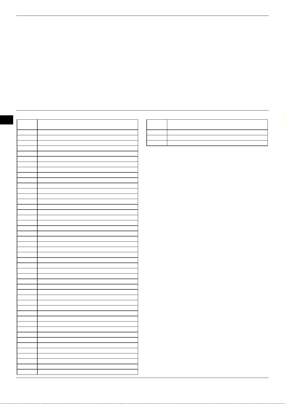
Technical characteristics of the product
Marking
Conformity marking
DN/NPS
PN/CLASS
PT [bar]
TS [°C]
Date of pressure test
Serial number/ year of production
Category acc. to PED
Category of fluid Liquid
Gas
List of contents:
1. Introduction
2. General warnings
3. Requirements for equipment used in potentially explosive
atmosphere according to Directive 2014/34/UE (ATEX)
4. Conditions of safe use
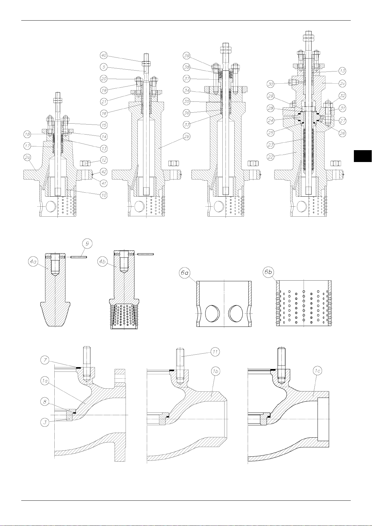
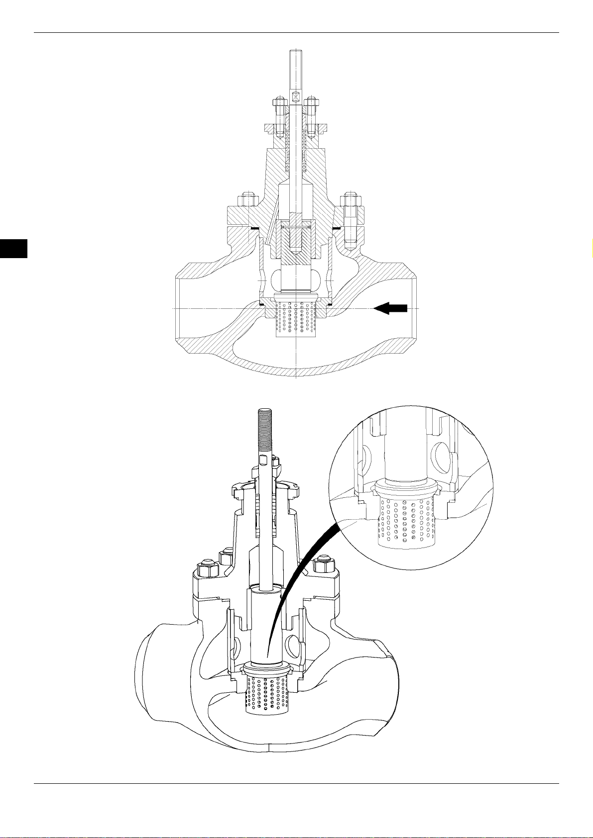
5. Design and operating principle
6. Dimensions
7. Normal operating conditions
8. Storage and transport
9. Installation
10. Start-up and assembly with drives
11. Service
12. Repair
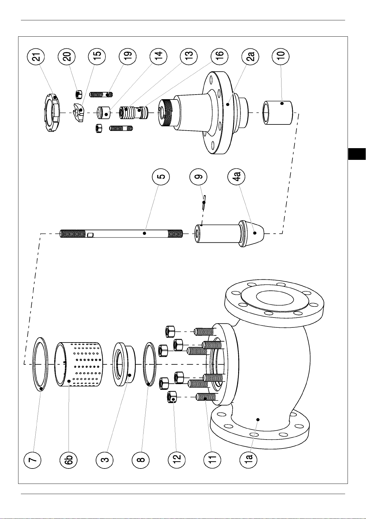
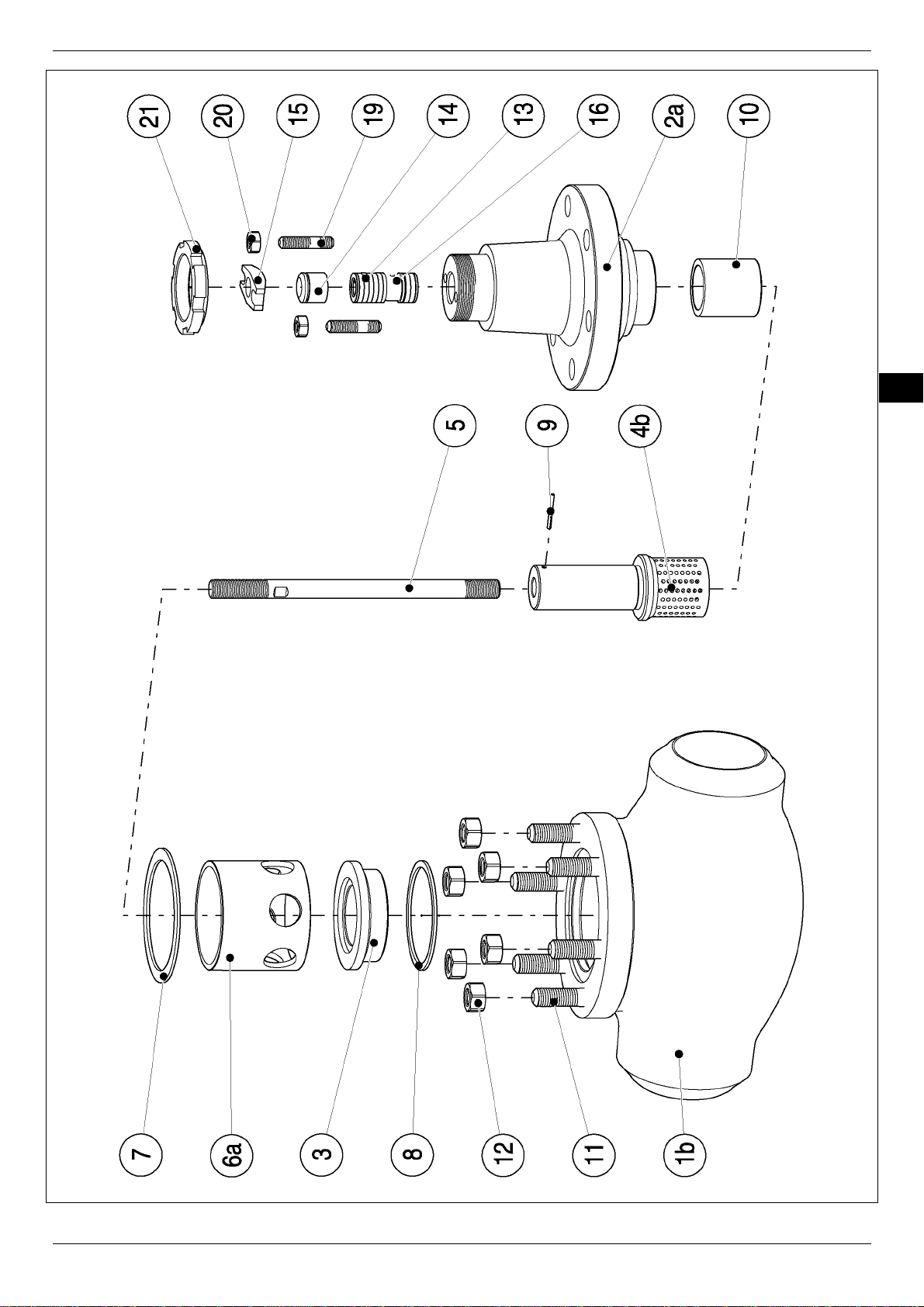
13. List of spare parts
14. Product disposal
15. Troubleshooting
1. Introduction
The Instruction manual for installation, operation and use is
intended for products designed and manufactured according to
the requirements of the ISO 9001 quality management system,
Pressure Equipment Directive (PED) 2014/68/EU, ATEX
directive 2014/34/UE and AD2000 Merkblatt regulations,
intended for installation on pipelines.
2. General warnings
WARNING
Prior to the product installation and use, read carefully
and follow the Instruction. All activities related to
installation, operation and use of the product have to be
carried out by appropriatly trained and skilled staff.
"POLNA" S.A., hereinafter also called the
manufacturer
,
has highly qualified service staff able to assist in
installation, maintenance and repairs of our valves.
The warning symbol in the Instruction means that
the content (of a WARNING or CAUTION message) is very
important due to safety reasons.
The product is intended for installation on pipelines.
Any other use has to be agreed with "POLNA" S.A. at the
stage of ordering of the product. If in doubt, contact
"POLNA" S.A. for explanation before performing any
further actions.
If the product is installed and maintained correctly, its
most ergonomic operation is ensured. However, it is
necessary to follow the requirements given in the
Instruction.
The product has to be installed and maintained
according to domestic and industrial regulations and
instructions.
The Instruction does not cover all cases and incidents
that may occur during installation, use and maintenance or
local safety regulations.
The content of the Instruction is of informative nature
and is considered to be true. The company reserves the
right to modifications, improvements and changes in the
technical data without notice.
"POLNA" S.A. is not liable for a valve selection made
by the buyer on his own or for operation and use of the
valve against its intended use. Failing to comply with the
provisions of this document, in particular when it comes to
use, repairs etc., will result in losing the guarantee and
warranty.
Z1A type control valves (Edition_
10/2022
)
EN