AQUAPHOR S800 User manual

AQUAPHOR WATER SOFTENER
Operation manual
S800, S800 P1

2
Congratulations on your purchase of a high quality filter for softening and deferrization of water
Aquaphor.
The Aquaphor water softener filter (hereinafter referred to as the softener) is a high-performance device
that removes high concentrations of hardness salts, iron and manganese, ensures long-term operation
without replacing the sorbent, and minimizes salt and water consumption during regeneration.
Please read this manual carefully before operating the product and keep it for future reference.
The manufacturer reserves the right to make changes to the design of the softener without reflecting
them in the instruction manual. This manual provides installation, operation and maintenance information
for the softener models S800, S800 P1.
Contents
Specifications 3
Source water requirements 4
Softener delivery set 4
General softener device 5
Appearance 5
Lid removal 5
Bypass valve 6
Controller 6
Control buttons 6
Controller Screen 7
Installing a softener 8
Step-by-step instructions for installing a softener 9
Controller setup 12
Quick Setup / Basic Settings 12
Mode of enhanced washing from iron 13
Advanced settings 13
Salt regeneration mode change 13
Recommendations for eective use softener 13
Safety regulations 14
Rules for storage and transportation 14
Disposal 14
Terms of Service and Warranties 14
Troubleshooting 16
Warranty coupon Aquaphor Softener 19
Installation information 19

3
Specifications
Maximum capacity, g 1680
Maximum compensated hardness, mg/l 1380
Maximum concentration of dissolved iron and manganese, mg/l* 12
Minimum pH 6
Temperature of water and environment, °C +5...+38
Water pressure, MPa 0,14–0,7
Minimum water flow for backwash, l/min** 7,6
Maximum flow to drain during regeneration, l/min 9,1
Nominal / maximum flow, l / min 25 / 38
Pressure loss at flow 22.7 l/min (6 gpm), MPa*** 0,1
Capacity in HE mode, kg of salt / gram of hardness 1,1 / 670
Capacity in HC mode, kg of salt / gram of hardness 3,0 / 1406
Maximum capacity in AU mode, kg of salt / gram of hardness 5,4 / 1680
Regeneration method Intelligent, by water meter
Power options 12 VAC; 50/60 Hz;
0.015 kWh
Connection ports (NPT) 1" (MNPT)
Minimum drain line diameter, mm (in) 16 (5/8)
Filtration tank size (ID × H), mm 267 × 584
Height, cm 70,6
Base, cm 40,4 × 48,5
Gross weight, kg 43
Filter medium and its quantity
Superfine monodisperse ion exchange resin, l 23
Quartzite, kg 0,8
or KDF85****, l 0,35
* Reducing the concentration of iron to 0.3 mg/l and below, manganese - to 0.1 mg/l and below.
** The flow rate must be checked at the end of the drain line.
*** For the correct selection of the filter, use the operating capacity and pressure drop. Long-term operation at flows higher than
those tested (more than 30 l/min) may lead to a decrease in cleaning efficiency.
**** Only for version S800 P1.

4
Source water requirements
Source water requirements Softener S800 Softener S800 P1
Water hardness, mg-eq / l* no more than 28
Content of divalent iron, mg/l* no more than 12
Content of ferric iron, mg/l no more than 0.3
Manganese content, mg/l* no more than 3
рН 6 to 9
Temperature, °C from +5 to +38
Content of oil products, mg/l no more than 1
Hydrogen sulfide, mg/l no more than 0.03 no more than 1
Permanganate oxidizability, mgО2/l no more than 5
Silicon, mg/l no more than 10
* The total “iron + hardness + manganese”, in terms of calcium carbonate, should not exceed the maximum compensated hardness
indicated in the “Technical characteristics” table.
ATTENTION! The softener does not purify water from colloidal iron or iron contained in organic complexes.
Softener delivery set
1. Complete softener 1 pc.
2. Overflow fitting 1 pc.
3. Drainage tube D=16 mm (5/8"), L=2.5 m 1 pc.
4. Flexible hose 1" by 3/4" (3/4" by 3/4") with o-rings 2 pcs.
5. Power supply 12 VAC 1 pc.
6. Controller 1 pc.
7. Drain pipe 1/2" 1 pc.
For Owner’s Reference
Aquaphor Softener Model
Serial #
Date of Installation:
Hardness:
Iron:
pH:
Water Pressure:
Water Temperature:

5
General softener device
Appearance
Lid removal
The lid can be removed by grabbing either the front or the
rear of the lid and pulling it straight up to access the valve
and controller.
Sorbent tank
Controller
Control valve
Lid
Support panel
Valve
Drain valve
Gravity overflow
connection
In Out
Bypass knob Bypass valve
Brine line
Salt cabinet
Brine cabinet
Side
Front

6
value of the compensated hardness, the current time, the
regeneration time are entered and the parameters of the
softener are selected, as well as the status of the device
is viewed. For the filter to work correctly, the controller
must be configured correctly.
The controller receives data on water consumption from
the flow meter. Based on these data and the selected
operating parameters, the controller starts the regener-
ation of the softener at the appointed time.
The controller saves settings in non-volatile memory even
after a power outage.
The controller is equipped with a non-volatile power sup-
ply that allows for two days to maintain the built-in timer.
Control buons
User Settings.
Change user settings.
Start regeneration manually. It is used
when the softener is connected for the
first time or for forced regeneration, for
example, if the softener runs out of salt.
Start regeneration manually.
1. Press and hold the button for about 5 seconds.
2.
The softener will start regenerating and will display the
current stage of regeneration on the display.
3. After all regeneration steps have been completed, the
display will return to normal operating mode.
Bypass valve
The softener is equipped with a bypass valve (fig. 1). The
bypass valve will allow you to turn off the softener in the
event of a malfunction or leakage. It also makes it possi-
ble to use untreated water for watering plants.
The bypass valve is located in the main control valve as-
sembly. To switch to the bypass line, turn the valve handle
to the “Bypass” position (fig. 1). Water will enter the
house past the softener, without treatment. To prevent
untreated water from entering the house, do not use the
water in the house when the softener is in Bypass mode.
Do not forget to switch the softener to normal operation
(filtration) by turning the knob to the “Service” posi-
tion (fig. 1), after repairing the device or using untreated
water.
To obtain water of comfortable hardness, you can use the
scheme shown in fig. 5, mixing the source water with
purified water.
NOTE: It is not recommended to use source water admix-
ture with high content of iron and/or manganese.
Controller
The controller has four control buttons, LCD display (fig.
2). The controller controls the valve actuators during re-
generation. Using the control panel of the controller, the
Figure 2
In Out
In Out
Figure 1

7
Interruption of a running regeneration cycle (only used
for system diagnostics).
4. Press and hold the button for 5 seconds after the
regeneration process starts.
5. The display will show the stage number (for example –
01).
6. If the controller does not move to the next stage with-
in 20 seconds, press and hold the button for about
2 seconds, the controller will proceed to the next stage.
NOTE: Each regeneration step can only be interrupted
once it has started. To move to the next stage of the re-
generation mode, press .
Enable / disable the hard hillshade
function.
This function can be performed as part of the service in
the following cases:
• operation of the softener on water containing dis-
solved iron,
• with a decrease in the quality of cleaning due to water
consumption, significantly exceeding the resource of
the softener before regeneration,
• with virtually no regeneration due to insufficient salt,
lack of input water or electricity.
In this mode, the softener will be flushed every other day,
consuming 2.3 kg salt per regeneration. The softener in
the mode of enhanced cleaning from iron should work for
at least 2 weeks. The increased frequency of regenera-
tions will help to remove the accumulated iron in the ion
exchange resin bed. This service procedure is recom-
mended to be carried out at least once a year.
Controller Screen
The main screen displays the volume of water in liters (or gallons) that will be
treated by the softener before the next automatic regeneration. On average, an
adult spends 280 l water per day. The volume of water until the next water re-
generation is indicated in hundreds or thousands of liters, depending on the val-
ue. For example, the number 33 would mean 33000 l if x 1000 is shown on the
display at the same time, and 3300l if this indicator is inactive.
During regeneration, the number of the stage currently in progress will flash on
the main screen:
01 – First backwash.
02 – salt regeneration / slow washing.
03 – second backwash
04 – topping up the brine tank.
HO – return to working position. After the regeneration is completed, the display
will again show the amount of water until the next regeneration in hundreds of
gallons or hundreds / thousands of liters. The duration of regeneration is 30–
40minutes.
Regeneration progress indicator. Indicates that the softener is auto-regenerat-
ing or a manual regeneration has started.
Water consumption indicator. “Droplets” on the display “run” as water flows
through the softener. It is convenient for monitoring water consumption and for
detecting water leaks.

8
Mode96h. When this mode is enabled, regeneration occurs once every three to
four days (72–96 hours) if there is no regular regeneration during this period of
time. This is necessary so that the dissolved iron extracted from the water does
not precipitate inside the softener. If there is dissolved iron and / or manganese
in the source water, the 96h mode must be turned on.
Time of day indicator. Displayed when the system is set to the time of day.
Regeneration time indicator. The dial with the symbol R is displayed if the time
of day is set for the regeneration process.
High hillshade indicator from iron is displayed when the function is active.
Installing a softener
The water softener must be connected in accordance with
local plumbing regulations.
To connect the softener, it is recommended to contact the
Aquaphor service department or Aquaphor regional dealers.
The connection, setup and operation of the device must
be carried out within the limits of operation specified in
this manual. Failure to comply with the requirements of
the passport can reduce the effectiveness of flushing and
lead to improper operation of the softener and its failure.
Before installing the softener, check the quality of the
water and the parameters of the water supply, power
supply and sewerage:
Water quality
Undissolved impurities
If the source water contains sand, sulfur, micro-organisms,
algae, oils or other impurities, the water must be pretreat-
ed.
We recommend installing an Aquaphor pre-filter.
Iron
The concentration of dissolved iron should not exceed
7 mg/l for the S800 softener, and it is also important to
know what form it is in.
• divalent iron (often referred to as “dissolved iron”)–
The only form of iron that can be removed by the
S800 softener.
• ferric iron (undissolved iron) – Precipitation of iron
hydroxide. Particles of such iron can clog the ion ex-
changer layer. Trivalent iron must be filtered before
water is supplied to the softener.
• iron in organic compounds – a dissolved form of
iron associated with organic compounds, usually hu-
mic or folic acids. Water containing iron in this form
is usually colored brown (“peaty water”). Additional
equipment is needed to remove this form of iron.
If the water contains ferrous iron, it is recommended to
flush the softener with an ion exchanger cleaner every
6months. Follow the instructions given in the ion exchang-
er cleaner data sheet.
Manganese
The manganese content should not exceed 3 mg/l.
ATTENTION! The total content of iron and manganese
should not exceed 7 mg/l.
The pH of the water must be greater than 6. If the pH
of the source water is less than 6, it is recommended to
install a corrective pH filter.
Hardness of water
Model S800 softens water with hardness up to 17 mg-eq/l
(840 mg/l in terms of CaCO3).
Water supply parameters
water pressureshould be within 0.14 to 0.7 MPa (1.4 –
7bar). For stable suction of the brine during regeneration,
it is recommended to supply water with a pressure of at
least 0.2 MPa (2 bar).
Plumbing performance
The minimum required flow for regeneration is 9 l in
aminute.

9
Water temperature not less than +5 and not more than
+38°C.
Sewerage
The unit drain must be routed to a waste water outlet,
such as a drain or washing machine drain, in accordance
with all local and national plumbing codes. An air gap or
siphon must be provided to prevent backflow (see the
“Installation and commissioning step by step” section).
Power supply
The power supply is designed for mains voltage of
220VAC with a frequency of 50 Hz. If there is a possibil-
ity of voltage deviation from the specified values by more
than 5–10%, use a voltage stabilizer. This will prevent
malfunctions and failure of both the power supply and the
electronic components of the softener.
ATTENTION! It is not recommended to separately con-
nect the softener to uninterruptible power supplies, as
this may cause failures in the regeneration process-
es. Connection is only possible in conjunction with
apumping station.
If you have any questions, please contact support. For
support information, see the General Information section
and the warranty card.
Step-by-step
instructions for
installing a softener
The softener connection must be made in accordance
with local plumbing codes.
The connection, setup and operation of the device must be
carried out within the limits of operation specified in this
manual. Failure to follow these guidelines may reduce flush
-
ing efficiency and result in softener malfunction or failure.
How to do:
• The softener must be installed after the hydraulic
accumulator tank and pump control automation sys-
tems.
• The softener must be installed in front of the water
heater and other appliances that consume water.
• The softener must be installed at least1m from heat-
ing appliances.
• It is not recommended to install the softener on
aheated floor, as this may cause excessive evapora-
tion from the brine tank and fouling of the softener
surfaces with salt crystals.
• Water for watering a lawn or garden does not require
softening and filtration, so this water can be drained
before the softener.
• When connecting the softener, it is recommended to
provide a bypass valve - “bypass” (see fig. 5). The by-
pass valve will simplify the maintenance of the soften-
er and will provide the supply of unsoftened water in
case of emergency when the softener is dismantled.
It is also recommended to drain the first portions of
contaminated water through the bypass after mainte-
nance work on the well, water supply or pump.
• If the length of the pipe between the softener and the
water heater is less than 3m, it is recommended to
install a non-return valve on this line as close as pos-
sible to the water heater. Make sure the water heater
is set to the correct temperature and the safety valve
is correct and in good working order.
You cannot do:
• Install and operate the softener in a room where the
temperature can drop below +5°C.
• Install and operate the softener in a room with humid-
ity over 70%.
• Install the softener near heating appliances.
• Connect the softener to the water supply in the op-
posite direction.
Step 1. Prepare a place for connection
• Turn off the power and water supply to the water
heater. For gas water heaters, additionally turn the
gas valve to the “Maintenance” or “Off” position. (See
instructions for your water heater).
• Turn off the water supply. Open hot and cold water
taps to relieve pressure in the lines. Check the water
supply for lime deposits, rust or other contaminants.
Clean or replace clogged plumbing.
• Organize the insertion point of the softener, according
to fig.3 so as to prevent axial distortions and tensions
during installation, as this can lead to damage to the
bypass assembly or softener valve.
• Arrange an electrical outlet at a distance of no more
than 2m.
NOTE: The bore diameter of the pipe from the accumula-
tor tank to the softener must be at least 3/4".
Step 2: Connect the softener to the water supply
The softener must be connected to the water line in ac-
cordance with national and local building, plumbing, and
electrical codes.
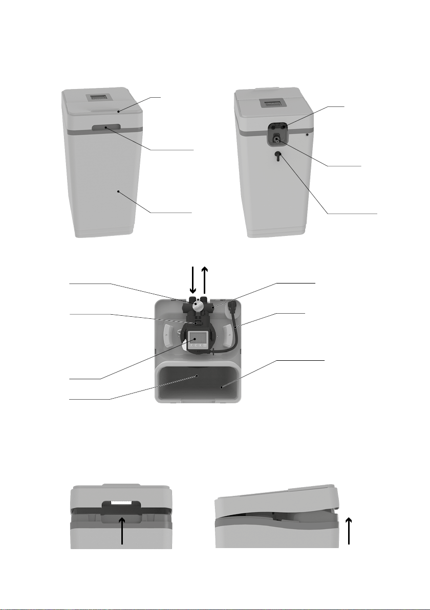
• Remove the softener cover by grabbing either the
front or the rear of the cover and pulling it straight up.
• Empty the salt compartment from all packaging and
installation materials.
• Make sure that the shims are inserted into the union
nuts of the flexible hoses. Connect the softener to the
water supply using flexible hoses.

10
NOTE: Teflon tape or sealant must not be used when
connecting with flexible hoses. When connecting with
other supply fittings, use only Teflon tape to seal the
connections.
• Check that the direction of water flow is correct using
the arrow on the bypass valve (see section “Bypass
valve”).
ATTENTION! Do not connect the softener to the water
supply in the opposite direction! This can lead to sof-
tener failure.
• Tighten the flexible hose nuts. Do not apply excessive
force so as not to damage the threaded part of the
fittings.
ATTENTION! To ensure the possibility of dismantling
the filter, it is recommended to use a bypass circuit
from standard components (fig. 5).
Step 3. Connect the overflow line
• The overflow line is designed to drain excess water
when the brine tank is overfilled or the softener de-
pressurizes.
• Screw the elbow overflow fitting included with the
softener into the hole on the back of the softener
housing and point downwards (see fig. 6).
• Install a flexible tube with an inner diameter 12 mm
(1/2”) (smaller tubing is not permitted) between an
overflow fitting and a drain, washing machine drain,
Gravity overflow connection
Figure 6Figure 3
Well water
Hard water for garden
and other needs
Shut-o valve
Municipal water
Electrical
outlet
Air gap
(5 cm minimum)
In Out
Water heater
Ground wire and clamps
(only for copper pipes) Cold “soft” water
Hot “soft” water
Drain and
overflow lines
Figure 4 Figure 5
Service position
(the appliance is on)
Bypass position
(the appliance is o)
Water supply is o
On
Water supply is o
On
O
PM PPM
In Out

11
or other suitable waste water outlet. This pipe is not
included with the softener.
• Removal of excess water through the overflow line oc-
curs by gravity. Make sure the overflow line terminates
at a drain that is at least 8 cm below the edge of the
overflow fitting. Provide an air gap of at least 5 cm.
• It is not allowed to bend the outlet tube of the over-
flow line and lift it in height.
ATTENTION! The overflow line is part of the emergency
leak protection system. In its absence, in case of mal-
function of the softener and overflow of the brine tank,
water leakage is possible.
Step 4 Connect the drain line
The drain line is designed to drain water during regener-
ation.
• Connect the drain line to the drain port (see fig. 7) us-
ing the 5/8” ID (~16mm) flexible hose supplied with
the softener. Reducing the diameter is not allowed.
• Run a drain line to a drain, washing machine drain, or
other suitable sewage outlet. Provide an air gap of at
least5 cm between the drain line and the maximum fill
level of the wastewater receiver in order to prevent
backflow.
• The drainage line must be laid in such a way that the
distance to the drain is minimal. The drainage line can
be raised to a height of up to 1.5 m above the drain
hole of the device, while the pressure in the water
supply must be at least 0.275 MPa (2.75 bar).
• The drain line may be extended with a pipe or hose
of at least 3/4”.
• The drain line must not be kinked, kinked, twisted or
otherwise damaged to restrict the flow of water.
ATTENTION! It is not allowed to combine drainage
(pressure) and overflow (gravity) lines by means of
tees, etc.
ATTENTION! During the regeneration process, small
solid particles may appear in the drain line, which does
not indicate a malfunction of the softener.
Step 5. Flushing the water supply
• Make sure the softener valve is in the “Bypass” posi-
tion (see fig. 1) Turn on the water supply.
• Open the nearest cold water faucet and flush the pipes
of solder flux residue and other foreign material.
NOTE: When the softener is in Bypass mode, the water
is not treated.
Step 6. Make sure the connections are tight
Close all outlet taps to pressurize the system.
Check all lines and connections for leaks. If a leak is found:
a) turn off the water supply;
b) fix all leaks;
c) turn on the water supply.
Slowly move the valve to the “Service” position (see fig.
1), slowly, to avoid water hammer, fill the softener.
Open the nearest cold water faucet to bleed air from the
system. When water comes out of the faucet without air,
close the faucet and check for leaks.
Step 7. Connecting the controller and power supply
NOTE: Make sure the controller is securely attached to
the three latches on top of the valve.
Connect to the back of the controller:
• flow sensor connector (fig. 8),
• motor connector,
ATTENTION! To ensure the possibility of dismantling
the filter, it is recommended to use a bypass circuit
from standard components (fig. 5).
Step 3. Connect the overflow line
• The overflow line is designed to drain excess water
when the brine tank is overfilled or the softener de-
pressurizes.
• Screw the elbow overflow fitting included with the
softener into the hole on the back of the softener
housing and point downwards (see fig. 6).
• Install a flexible tube with an inner diameter 12 mm
(1/2”) (smaller tubing is not permitted) between an
overflow fitting and a drain, washing machine drain,
Gravity overflow connection
Figure 6
Figure 7 Figure 8
Sensor wire Motor wire
Power cord

12
• power supply connector.
• Lay the power supply wire at the outlet of the wa-
ter lines. Connect the power supply to an outlet.
• Make sure the outlet to which the softener is con-
nected does not have an ON/OFF switch.
Step 8. Adjust the softener controller according to
the Controller Setup section.
Step 9. Rinse the softener
• Pour 8 l of water into the brine tank.
• Make sure the softener is in filtration mode and the
water supply is turned on.
• Perform a forced regeneration. To do this, press and
hold the Rbutton for about 5 seconds until the num-
bers 01 appear on the display and the regeneration
process starts.
• During the regeneration, which lasts 30–40 minutes,
the device will first take and then add water to the
brine tank to the desired level.
ATTENTION! The brine tank should only be filled with
water when the softener is started. After starting, top-
ping up water is carried out automatically.
Step 10. Load Salt into the Brine Tank
Load salt into the brine tank up to 25 kg. Use refined table
salt or granulated table salt (NaCl). Do not use these two
types of salt at the same time. Use only high-quality tab-
leted or granulated salt, such as AQUAPHOR. Poor quali-
ty salt can cause a decrease in the efficiency of regener-
ation or the failure of the softener.
NOTE: Always keep the salt level above the water level.
For convenience, when adding salt, fully load the tank.
After adding salt, including adding after salt is complete-
ly used up, wait at least two hours before starting regen-
eration. This is necessary for the formation of a saturated
saline solution.
Step 11. Complete the installation process
Make sure the bypass valve is in the “Service” position
(see fig.1).
Make sure the water supply is turned on.
If there is an external bypass circuit, make sure the taps
are in the correct position (see fig. 5).
Turn on the power and water supply to the water heater
(if any). For gas water heaters, turn the gas valve to the
“Operation” position (see the instructions for your water
heater).
Open the nearest cold water faucet and run the softener
for 20 minutes or until about 270 liters water.
Make sure that the water consumption indicator on the
controller display is working – this indicates the water
consumption and the operation of the liter counter.
Replace the softener cover.
Controller setup
For the correct operation of the softener, it is necessary
to enter into the processor data on the content of hardness
salts, iron and manganese in the water.
To do this, it is necessary to calculate the total parameter,
which will include all these pollutants. This parameter is
called “compensated stiffness”.
Generally, in water analysis, total hardness is expressed
in mg-eq / l.
ATTENTION! German (DH) and French (ºF) are differ
from mg-eq / l.
To calculate the “compensated stiffness”
it is necessary:
• Multiply the number of mg-eq / l by 50.
• Add the concentrations of iron (mg/l) and manganese
(mg/l) and multiply the sum by 85.
• Add up both items.
EXAMPLE:
Total hardness = 6.84 mg-eq / l
Ferrous iron (dissolved) = 3 mg/l
Manganese = 1 mg/l
Compensated stiffness = 6.84 × 50 + (3+1) × 85 = 682
Note. If the total hardness is presented in the analysis as
a concentration of CaCO3(mg/l), it is not necessary to
multiply the value by 50.
EXAMPLE:
General hardness = 342 mg/l CaCO3
Ferrous iron (dissolved) = 3 mg/l
Manganese = 1 mg/l
Compensated stiffness = 342 + (3+1) * 85 = 682
If you have any questions, please contact Aquaphor sup-
port.
Quick Setup / Basic Seings
Step 1. Set the hardness value
A. Click . After approximately 4 seconds, the con-
troller will beep and the display will show ppm
B. Press until the number on the display corre-
sponds to the required hardness to be compensated
(see section “Checking before installation”).
C. Click to save the settings and proceed to the
next step.
Step 2. Setting the current time
A. Press until you set the current hour. Press
to save the setting and move on to setting the min-
utes.
B. Press until you set the current minutes. Press
to save the setting and go to the home screen.
NOTE: The current time is shown in 24 hour format.

13
Mode of enhanced
washing from iron
Step 1. Turning on / off the enhanced iron
cleaning mode
Press and hold to turn the feature on or off. In the mode
of enhanced cleaning from iron, a more intensive washing
of the softener with saline occurs, which contributes to
more efficient cleaning of the sorbent from iron. When this
mode is enabled, regeneration occurs every other day. To
achieve the desired effect, the mode of enhanced iron
washing should be switched on for at least 2 weeks. De-
pending on the iron content of the water, it is recommend-
ed to carry out this procedure at least once a year.
Advanced seings
Advanced settings allow you to select the brine regener-
ation mode, turn on the 96h mode, change the liter/gallon
and mg/L/gpg units, and set the regeneration start time.
Please be careful when using advanced settings.
Salt regeneration mode change
A. Press and hold and for about 4 seconds, the
controller will beep and display the brine regenera-
tion mode on the display.
B. Press to cycle through AU, HC, and HE modes.
Press to save the selected option and proceed
to step 2.
Salt regeneration modes:
AU (Auto mode) – in this mode, the controller monitors
the daily water consumption and regulates the
amount of salt for regeneration. If the 96h mode is
disabled, the controller will regenerate 2 times a
week if there is water demand.
HC (High capacity mode) – fixed setting of salt regen-
eration, which allows less frequent washing of the
sorbent.
HE (High economy mode) – fixed salt regeneration set-
ting, which reduces the amount of water to be treat-
ed between flushes, but significantly saves salt.
Enabling / Disabling the forced regeneration mode “72-
96 hours”
In this mode, the controller will regenerate automatically,
at the appointed time once every 3–4 days, if normal
regeneration did not occur during this interval.
Press to turn 96h mode on or off. The display on the
right side will show or turn off the indicator 96h. Click
to save your settings and move on to the next step.
96h mode. Activation of the 96h mode ensures that the
regeneration process is carried out at least 2 times
aweek. This mode must be switched on if there is iron
and/or manganese in the source water.
NOTE: More frequent regenerations help the softener to
recover more eectively from iron.
Unit switching: gallon / liter
Press C to switch gallon/liter units. The changes will be
displayed on the screen as gallons or liters. Click to
save your settings and move on to the next step.
Setting the regeneration start time
A. Press to set/change regeneration start time
(hours). Press to save the settings and go to the
minutes setting.
B. Press to change the minutes at which regener-
ation starts. Click to save the settings and go to
the home screen.
NOTE: Time is shown in 24 hour format.
Recommendations for
effective use softener
To get the most out of your softener, follow these
guidelines:
• Add salt if the level is below the water level in the
brine tank. The salt level must always be at least 1/3
of the full load.
• It is recommended to use pure salt in tablets or gran-
ules. Don’t use rock salt.
• Once every 6 months it is recommended to use an ion
exchanger cleaner.
ATTENTION! Do not mix different types of salt.
• In the event of a power outage, check the correctness
of the controller settings (type of regeneration, water
parameters, time); if necessary, set the correct values.
(See the Controller Setup section).
• Program the softener to regenerate at times of the
day when you don’t normally use water. If you have
several water treatment devices that require regener-
ation, the time between device regenerations should
be at least two hours.
• Please note that other water-using devices, such as
washing machines and dishwashers, should not be
running while the softener is regenerating.
• Protect the softener from freezing, including the drain
line.
• Follow the requirements for operation, maintenance
and placement of the softener.
• If the softener runs out of salt during operation: add
salt; wait at least two hours for the salt to dissolve and
then start the regeneration. To do this, press and hold
the Rbutton for 5 seconds; regeneration will be com-
pleted in approximately 30–40 minutes, after which
the softener will return to normal operation.

14
• If the incoming water contains sediment, sand or oth-
er undissolved particles, a pre-filter should be used.
For example, pre-filter Aquaphor Gross or Gross Midi.
• The device can be disinfected with 5.25% sodium
hypochlorite solution, which is the active ingredient
in household bleach. To disinfect the device, pour
120ml of bleach solution or 25 ml of concentrated
sodium hypochlorite solution into the brine tank’s
brine shaft. There must be water in the brine tank.
Start regeneration manually.
• Use the bypass to flush the plumbing after repair or
maintenance.
• Check and clean the brine tank and air release valve
annually or when sediment appears in the tank.
Safety regulations
• During operation, observe the general electrical safe-
ty rules when using electrical appliances.
• It is forbidden to repair the softener by persons who
do not have special training.
• Before connecting, check that the mains voltage
matches the operating voltage of the softener’s pow-
er supply.
• It is forbidden to use homemade adapters and exten-
sion cords. Protect the electrical cord from damage.
Precautions when connecting
your Softener to the mains
Check that the main voltage matches the parameters
specified in this Manual before connecting your Softener
to the mains. Only use a power supply unit with output
characteristics specified in this Manual.
Make sure that your Softener is protected from freezing,
water, direct sunlight, contact with hot objects, including
hot water, heating pipes and heating devices before in-
stalling. Keep your Softener from hitting and falling.
The power cord must not be tensioned when your Soften-
er is connected. Make sure that the power cord does not
touch surfaces that could damage it.
Do not immerse the Softener, as well as the AC adapter,
power cord, and power cord plug, in water or other liquid,
and do not wash them under running water or in a dish-
washer.
To avoid electric shock, do not touch your Softener
connected to power with wet hands, as well as the
power supply unit, the power cord and the plug.
Keep your Softener housing clean. Disconnect your Sof-
tener from the power supply and wipe, if necessary, with
a dry cloth.
Do not disassemble your Softener
nor open its housing!
Do not use the Softener and the power supply in case of
malfunction or damage to the cord. Do not repair the device
yourself. First disconnect the power supply from the mains,
then disconnect it from the Softener if any malfunction is
detected. It is recommended to contact your service provide.
Rules for storage and
transportation
• The softener is stored in a polyethylene package, in
a closed cardboard container, in enclosed spaces
with natural ventilation, at a relative humidity of not
more than 80%, at a temperature not lower than +5 °С
and not higher than +38 °С. The shelf life before the
start of operation is no more than 2 years.
• The softener is transported and stored in an upright
position. It is forbidden to tilt the softener, subject it
to shocks and other mechanical influences.
• The softener is transported packed by any type of
covered transport in a fixed state.
Disposal
Disposal in accordance with environmental, sanitary and
other requirements established by national standards in
the field of environmental protection and ensuring the
sanitary and epidemiological welfare of the population.
Terms of Service
and Warranties
Aquaphor water Softener – Two Year Warranty from the
date of purchase under normal use and service. This does
not apply, however, to filter material and/or ion exchange
resin.
Exclusions and Limitations
• Aquaphor warrants its products to be free from
manufacturing defects under normal use and service.
This warranty is extended only to the ORIGINAL
PURCHASER.
• Aquaphor obligations under this warranty are limited
to repairs or replacement, at Aquaphor’s option, of
products or parts found to be defective, provided that
such products were properly installed and used in
accordance with instructions. Aquaphor reserves the
right to make such inspections as may be necessary in
order to determine the cause of the defect. Aquaphor
will not charge for labor or parts in connection with
warranty repairs for the first full year from date of
purchase on all products except those that may be
subject to commercial use limitations.
• Aquaphor is not responsible for the cost of removal,
return (shipping) and/or reinstallation of products.

15
This warranty does NOT apply to:
Damage or loss which occurs during shipment.
Damage or loss sustained through any natural or man-
made causes beyond the control of Aquaphor, including
but not limited to fire, earthquake, floods, etc.
Damage or loss resulting from sediments or foreign mat-
ter contained in a water system.
Damage or loss resulting from negligent or improper in-
stallation including installation of a unit in a harsh or haz-
ardous environment.
Damage or loss resulting from removal, improper repair,
modification of the product, or improper maintenance
including damage caused by chlorine or chlorine related
products.
Damage or loss resulting from acts which are not the
fault of Aquaphor or which the Product is not specified
to tolerate.
This warranty gives you specific legal rights. You may have
other rights which may vary from state. to state
THIS WRITTEN WARRANTY IS THE ONLY WARRANTY MADE
BY AQUAPHOR. REPAIR OR REPLACEMENT AS PROVIDED
UNDER THIS WARRANTY SHALL BE THE EXCLUSIVE REM-
EDY AVAILABLE TO THE PURCHASER.
AQUAPHOR SHALL NOT BE RESPONSIBLE FOR LOSS OF
USE OF THE PRODUCT OR FOR OTHER INCIDENTAL,
SPECIAL, FOR CONSEQUENTIAL DAMAGES OR EXPENSES
INCURRED BY THE PURCHASER OR FOR LABOR OR OTH-
ER COSTS DUE TO INSTALLATION OR REMOVAL OR COSTS
OF REPAIRS BY OTHERS, OR FOR ANY OTHER EXPENSE
NOT SPECIFICALLY STATED ABOVE. EXCEPT TO THE EX-
TENT PROHIBITED BY APPLICABLE.
LAW, ANY IMPLIED WARRANTIES, INCLUDING THAT OF
MERCHANTABILITY, ARE EXPRESSLY LIMITED TO THE
DURATION OF THIS WARRANTY. SOME STATES DO NOT
ALLOW LIMITATIONS, SO THE ABOVE LIMITATION AND
EXCLUSION MAY NOT APPLY TO YOU.
Any defects covered by this warranty should be promptly
reported to the AQUAPHOR: AQUAPHOR INTERNATIONAL
OÜ, L. Tolstoy 2A, Sillamäe, Estonia, 40231.
www.aquaphor.com
The service life of the softener (excluding filter material
and/or ion exchange resin) is not more than 5 years from
the date of sale (determined by the shop stamp in this
manual).
The softener shelf life is 2 years before operation when
stored at + 5 to + 40 ºС, without breach of packaging.
If you have any issue with the operation of your Softener,
please, contact the seller or the manufacturer.
For further information on parts and service please contact
EU customer service department at: +3723924116;
+48228702432 sales@aquaphor.com,
www.aquaphor.com

16
Troubleshooting
Probable Cause Solution
Problem: No soft water output after softener regeneration
There is no salt in the brine tank Sprinkle salt
Solids in the brine tank clogged the brine line, brine
valve, air check valve or injector
Dismantle the brine line together with the air cut-off
valve Air check. Rinse them with clean water.
Clean brine valve and injector. Remove impurities from
the salt tank
Clogged or improperly installed brine line flow restrictor Dismantle the brine valve, clean and properly install the
restrictor salt flow
Drain line kinked, frozen, or clogged Straighten the line, let it thaw or clean it
Clogged injector Remove the injector cap, clean the nozzle with a wooden
toothpick. Reinstall the removed items.
A salt bridge has formed (appearance of salt) in the salt
compartment due to high humidity or the use of the
wrong type of salt
Try to break the crust with a blunt object, you can use
hot water. Add salt if there was none. Use only high
quality granular or tablet salt.
Problem: No soft water at softener outlet
Bypass valve is in Bypass position or deviated from
Service position
Set bypass valve to normal operation. Service
The device is connected to the water supply
in the opposite direction
Check if the device is connected correctly
Prolonged power failure Reset the current time
Lack of accounting for water consumption See if the water consumption indicator on the softener
works when the water is being drawn. If not, see below.
The composition of the source water has changed Explore the water, make changes to the settings
according to the new data
Raw water is mixed with purified Make sure that there is no mixing of raw water
Problem: Sensor registers water flow when water is not flowing
Water leak after softener Fix the leak
Problem: No indication on the display
Power wire not connected Connect the power supply
No mains power Check for power at the outlet.
Faulty power supply Check the power supply with a voltmeter. Should be 12
VAC. If the voltage is less than 10 VAC, check the voltage
at the 220 VAC outlet
Faulty controller If 12 VAC is being supplied to the controller, replace the
controller
High ambient temperature. At air temperature +38°Cor
higher, the display will not show characters. The
functionality of the controller is preserved
No option but to lower the temperature
Problem: The device does not exit the regeneration mode
Controller incorrectly installed Make sure the controller is fixed on the screw mechanism
cover correctly
Defective magnetic arm Replace magnetic arm
Foreign object in control valve mechanism Disassemble valve, remove foreign object
The control valve is out of order, the engine is running Repair or replace control valve

17
Probable Cause Solution
Problem: Excess water in brine tank
Drain line clogged, kinked, or frozen Remove the blockage, straighten the kink in the drain line
Clogged brine line, brine line flow restrictor or Air check
valve
Clean the brine line, brine line flow restrictor and air
check valve. Remove dirt from the salt tank
Clogged injector Clean or replace injector. If the injector neck has been
removed, replace it with a new one.
Problem: Regeneration sequence broken
Damaged magnetic lever Replace magnetic arm
Faulty controller Replace controller
Problem: Salt water outlet
Damaged injector Replace injector including neck
Low inlet water pressure Minimum working pressure 0.14 MPa
Drain restrictor clogged Remove blockage
Salt line clogged or damaged Remove blockage, replace line if damaged
Too much water in brine tank Check that the water level in the tank* and the brine
regeneration settings are correct. Check brine, drain
lines and tightness of valve assemblies
Unstable pressure of the supplied water, the formation
of a vacuum at the inlet
Install a check valve before
softener. Stabilize the inlet pressure
Brine valve leak Clean brine valve, replace brine valve seals
Problem: Ошибки контроллера
E1 - Home position not detected Turn the power off and on by unplugging and plugging in
the AC adapter. The search for the home position will
start again.
Make sure the controller is fully and securely attached to
the screw mechanism cover
E2 - Engine malfunction Disable email. power and connect the motor. If it was
already connected, replace the motor.
Make sure the power supply is 12V AC
E3 - Shift Home The magnetic arm does not start from the correct home
position. The controller will automatically attempt to
adjust by searching for the home position and continue
regeneration.
Make sure the controller and magnetic arm are fully and
securely attached.
E4 - Home position locked Transmission teeth not engaged or stripped. Something
has jammed the valve mechanism. Clear the jam, then
power cycle the softener to clear the error.
E5 - Memory error To clear the error, turn the power off and on. If error
persists, replace controller.
* The water level must not reach the level of the float and the overflow fitting.

18

19S800-S800 P1_v1
For further information on parts and service please contact EU customer service department at
+ 372 39 24 116; + 48 22 870 24 32 sales@aquaphor.com, www.aquaphor.com
The Quality Management System
is certified according to ISO 9001.
The manufacturer reserves the right to make improvements to the design of the Aquaphor water
softener without being mentioned in this Manual.
Manufacturer: AQUAPHOR INTERNATIONAL OÜ, L. Tolstoi 2A, Sillamäe, Estonia, 40231. www.aquaphor.com
Warranty coupon Aquaphor Softener
Aquaphor Softener Model
Serial #
Date of Sell
Seller’s stamp
Seller’s signature
Installation information
Name of the company which
carried out installation:
Name of the service engineer:
Service engineer’s signature:
Client’s signature:
For installation, operational
and technical maintenance,
please, contact:

Aquaphor water softener models:
The number of the Aquaphor water softener model,
the manufacturing and quality control date, as well
as the product’s serial number are indicated on a special
sticker on this page.
S800
1S800 P1
2
This manual suits for next models
1
Table of contents
Other AQUAPHOR Water Dispenser manuals
Popular Water Dispenser manuals by other brands

Water Right
Water Right Sanitizer Plus Series Installation instructions & owner's manual

Ice-O-Matic
Ice-O-Matic GEMD270A2 Installation and service manual

DE VECCHI
DE VECCHI DVA AL Series technical information

Scalemaster
Scalemaster SL100 Installation Procedures & Operating Manual

Rheem
Rheem RHS42 Installation and operation manual

Kenmore
Kenmore 625.384600 owner's manual