4
AQUASURE HARMONY SERIES
II. Installation Safety Guide
IMPORTANT! The following conditions for feed water supply must be met or warranty will be
void and the manufacturer assumes no responsibility for damage to system or property.
1. Water Temperature Parameter
The system MUST NOT be installed in an area where it is exposed to direct sunlight and must
be protected against freezing and extreme heat.
• Maximum: 100° F (37.8° C)
• Minimum: 32° F (0° C)
2. Water Pressure Parameter
The maximum allowable inlet water pressure is 125 psi. If daytime pressure is over 80 psi,
night time pressure may exceed the maximum allowed water pressure. Use a pressure
reducing valve (PRV) to reduce the pressure if needed.
• Maximum: 125 PSI (8.78 kg/cm2)
• Minimum: 25 PSI (1.75 kg/cm2)
3. Chlorine & Chloramine Tolerance
Softener resin may degrade in the presence of chlorine or chloramines. Feedwater that
contains these contaminants will reduce the life of the resin. In these conditions, a whole
house carbon ltration system with chlorine, chloramine reducing media is recommended.
• Maximum: 2 ppm
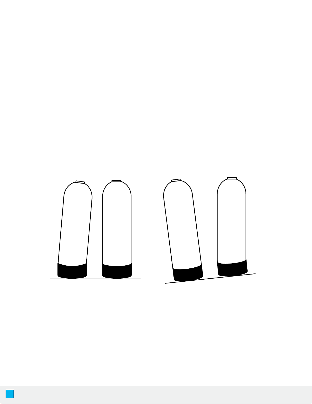
4. Pre-install environment checklist
• Not for use with microbiologically unsafe water. Pre-ltration to remove contaminants
and heavy sediment recommended to ensure optimum performance and product life.
• Properly ground to conform with all governing codes and ordinances. Use only lead-free
solder and ux for all sweat-solder connections as required by state and federal codes.
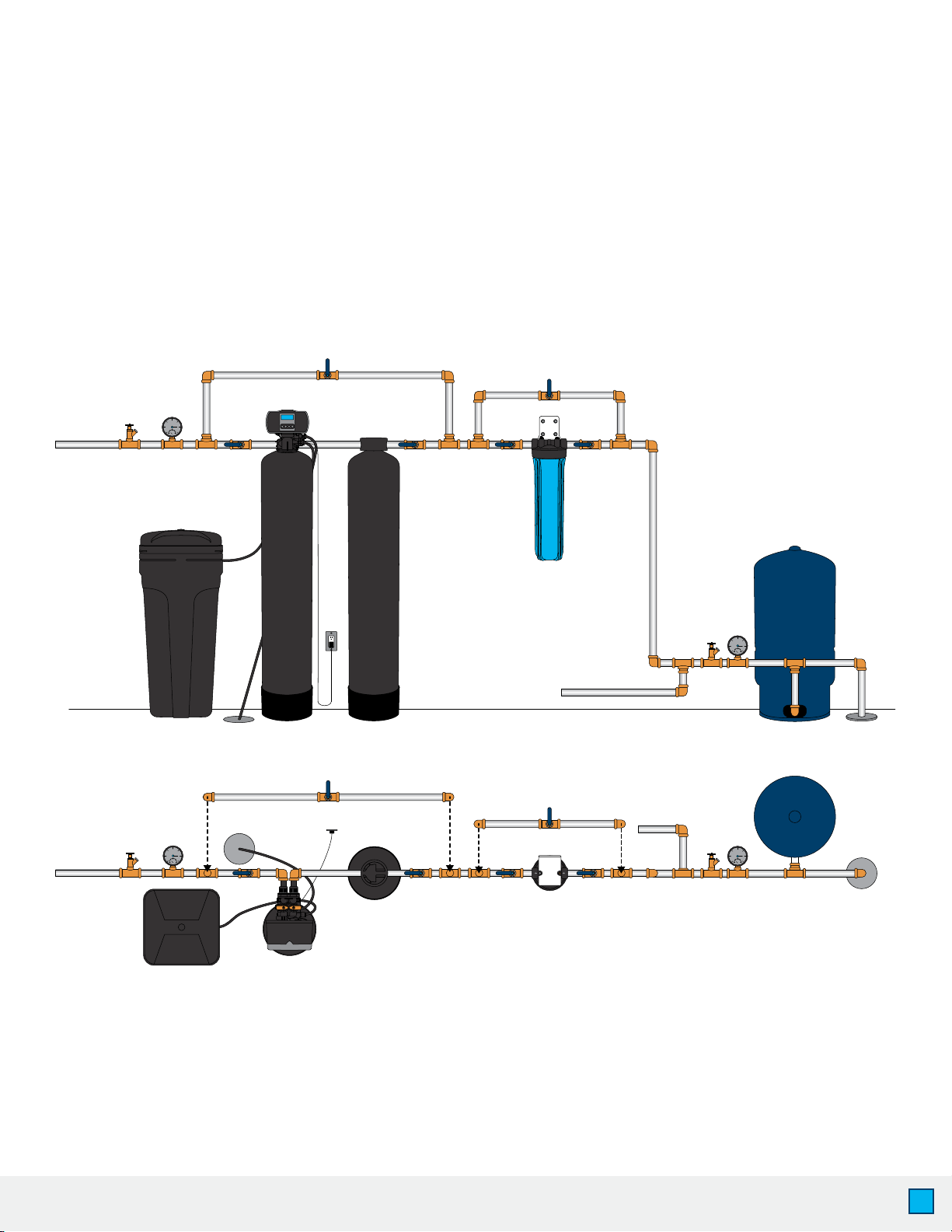
• Place softener as close as possible to the pressure tank (well system) / water meter (city water).
• Place softener as close as possible to a oor drain, or other acceptable drain point
(laundry tub, sump, standpipe, etc.) to prevent air breaks and back ow.
• Place softener in a place where water damage is least likely to occur if a leak develops.
• The brine tank should be located no more than 10’ from the resin tank.
• Connect the softener to the main water supply before the water heater. Do not run hot
water through the softener. Maximum temperature of softener water is 100º F.
• Outside faucets and irrigation systems should be supplied with pre-softened water. If this
is not possible, be sure to bypass the softener when watering grass or plants. Chronic soft
water exposure can be detrimental to plant life.
WARNING! For your safety, the information in this manual must be followed to minimize the
risk of electric shock, property damage or personal injury.