manuals.online logo
Brands
  1. Home
  2. •
  3. Brands
  4. •
  5. aQuatell
  6. •
  7. Water Dispenser
  8. •
  9. aQuatell Fleck 5600SXT User manual

aQuatell Fleck 5600SXT User manual

Popular Water Dispenser manuals by other brands

IBC Water AST0715MP-960 Installation & operating instructions

IBC Water

IBC Water AST0715MP-960 Installation & operating instructions

Lancaster Water Treatment X FACTOR LX15 Series Installation, operating and service manual

Lancaster Water Treatment

Lancaster Water Treatment X FACTOR LX15 Series Installation, operating and service manual

Elkay EMABF8 Series Installation & use manual

Elkay

Elkay EMABF8 Series Installation & use manual

Oasis Osmosis Home installation manual

Oasis

Oasis Osmosis Home installation manual

Monarch Water ULTIMATE MINI AQUA HE install guide

Monarch Water

Monarch Water ULTIMATE MINI AQUA HE install guide

Haier HLM-109B instruction manual

Haier

Haier HLM-109B instruction manual

GE GXOF18G Owner's manual and installation instructions

GE

GE GXOF18G Owner's manual and installation instructions

Kenmore 625.385560 UltraFilter 650 owner's manual

Kenmore

Kenmore 625.385560 UltraFilter 650 owner's manual

Aries Hydra DI Operation & maintenance manual

Aries

Aries Hydra DI Operation & maintenance manual

Avanti WD31EC instruction manual

Avanti

Avanti WD31EC instruction manual

GE GNCF02H owner's manual

GE

GE GNCF02H owner's manual

Avanti WD360 instruction manual

Avanti

Avanti WD360 instruction manual

ProFlo PFB Series Installation & operation manual

ProFlo

ProFlo PFB Series Installation & operation manual

Frakco Travelsoft RV 2400HD Operation instructions

Frakco

Frakco Travelsoft RV 2400HD Operation instructions

Aqua Essentials Borg & Overström B4 user guide

Aqua Essentials

Aqua Essentials Borg & Overström B4 user guide

KENT 11063 Instruction handbook

KENT

KENT 11063 Instruction handbook

Calmat Plus user manual

Calmat

Calmat Plus user manual

Igloo MWC529 instruction manual

Igloo

Igloo MWC529 instruction manual

manuals.online logo
manuals.online logoBrands
  • About & Mission
  • Contact us
  • Privacy Policy
  • Terms and Conditions

Copyright 2025 Manuals.Online. All Rights Reserved.

Fleck 5600SXT Water Softener Instructions
Overview
Thank you for your water softener purchase from aQuatell. We appreciate your business and
look forward to serving you in the future.
This instructional manual is intended to aid you in the installation and programming of your
newly purchased water softener. The programming instructions provided here are abbreviated
versions of the full manufacturers instructions and you may wish to reference the manufacturer
instructions for further details. It’s important to note that the images in this manual are not
necessarily to scale.
We ask that you fully read these instructions and contact us with any questions before you begin
the installation process. In many situations, installing a water softener means turning off your
water for some period of time. If you find yourself with questions half way through the
installation, you may be without water until the question has been resolved. We can be reached
by phone weekdays between 9am - 5pm Eastern time: 1-866-966-9951.
Delivery of your Softener
Your water softener is delivered in several boxes. One box will contain the softening tank and
brine tank. Another box will contain the valve and other installation items. The resin will ship in
either one or two boxes depending on the size of softener purchased. When you receive your
shipment inspect it for any obvious signs of damage. If your shipment has been damaged please
report this immediately to aQuatell.
Before you Begin
Before you begin the installation it’s a good idea to identify all of the components:
Brine Tank Box(es) of resin Resin Tank
Page 1
Fleck 5600SXT U.S. V1.1
Copyright aQuatell Inc 2010
Softener Valve Bypass Valve / Plumbing Adapters
Riser Tube
Brine Well (with float assembly) Brine Line
Riser Tube Upper Media Screen Brine Line Adapter Kit (doesn’t include hose)
Page 2
Fleck 5600SXT U.S. V1.1
Copyright aQuatell Inc 2010
or
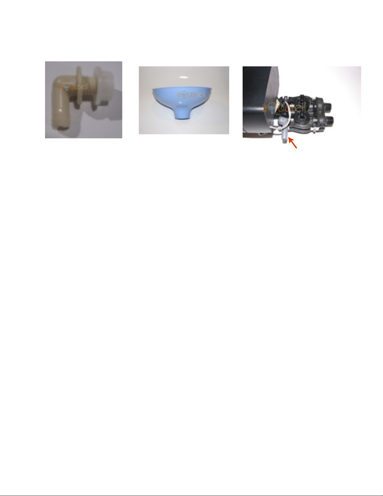
Overflow Bulkhead Fitting Funnel Drain Line Barb
Putting it all together - Overview
Once you’ve identified all of the components of your softener, you’re ready to begin the
installation. First, you’ll want to locate a good spot for your softener. All parts of your water
softener should be located in a protected, dry, level, non-freezing area. The water softener needs
to be located in very close proximity to your water main, and also needs to be located close to a
drain. Suitable drains include a floor drain, sump pit, washing-machine drain, or (where
regulations permit) an outside downspout or gutter drain. It’s important that you identify and
follow any local plumbing codes for the installation of your softener.
The drain line can be routed down to the floor or overhead. Whichever method is used please
ensure that all turns are gradual to prevent kinking in the line. Be sure to secure the drain line in
place as the pressure of the draining softener will move an unsecured line.
The softener you have purchased requires power in order to operate the valve. Ideally, you
should position the water softener a few feet from a power outlet. aQuatell recommends that all
water purification equipment, including softeners, be plugged into a Ground Fault Circuit
Interrupter (GFCI) outlet.
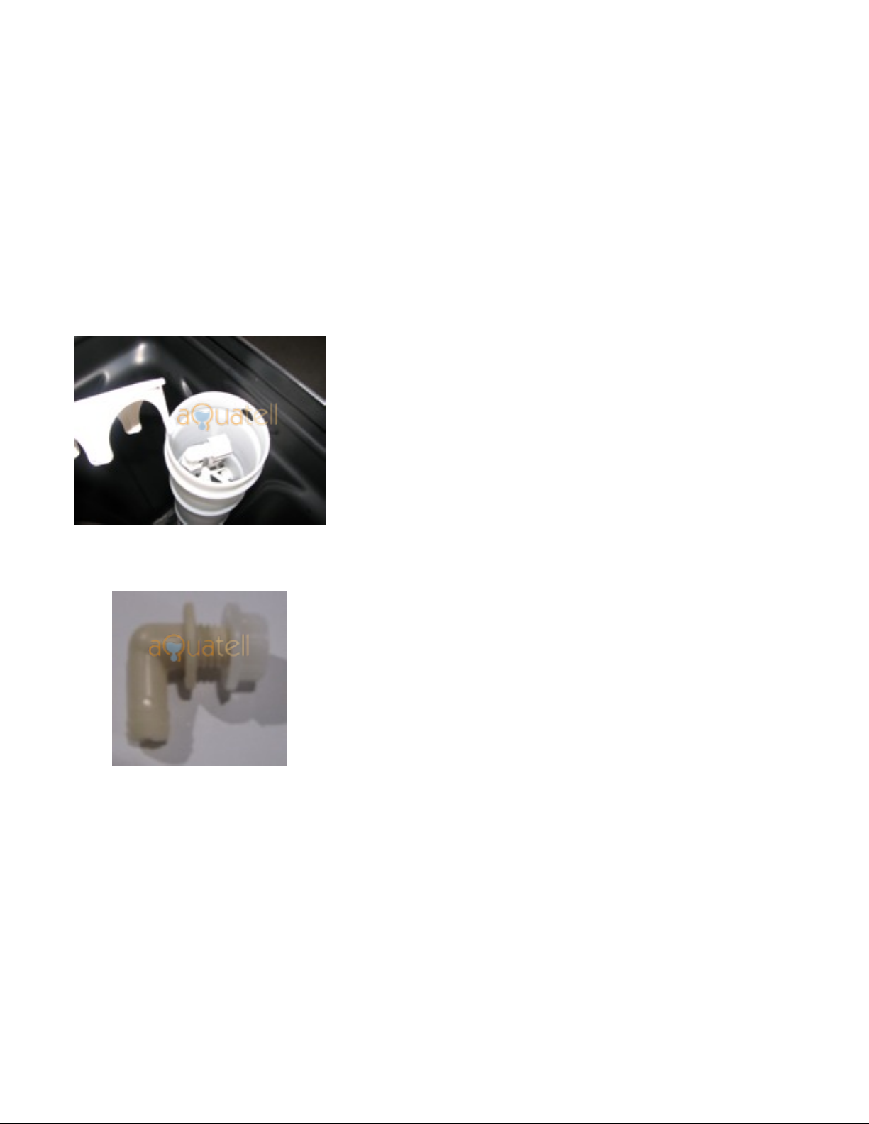
Check that the resin tank is sitting flat in the black plastic boot on the bottom of the tank. If the
boot appears to be on an angle push down on the resin tank and rock the tank very slightly back
and forth to lower the resin tank fully into the boot.
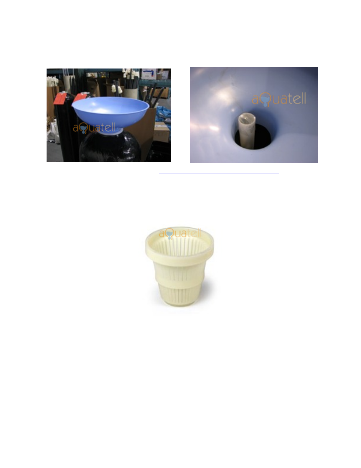
Putting it all together - The Softening Tank
The softening tank houses the resin and is where the softening of your water occurs. The
softening tank is the cylindrical tank with a threaded opening at the top. Set the softening tank in
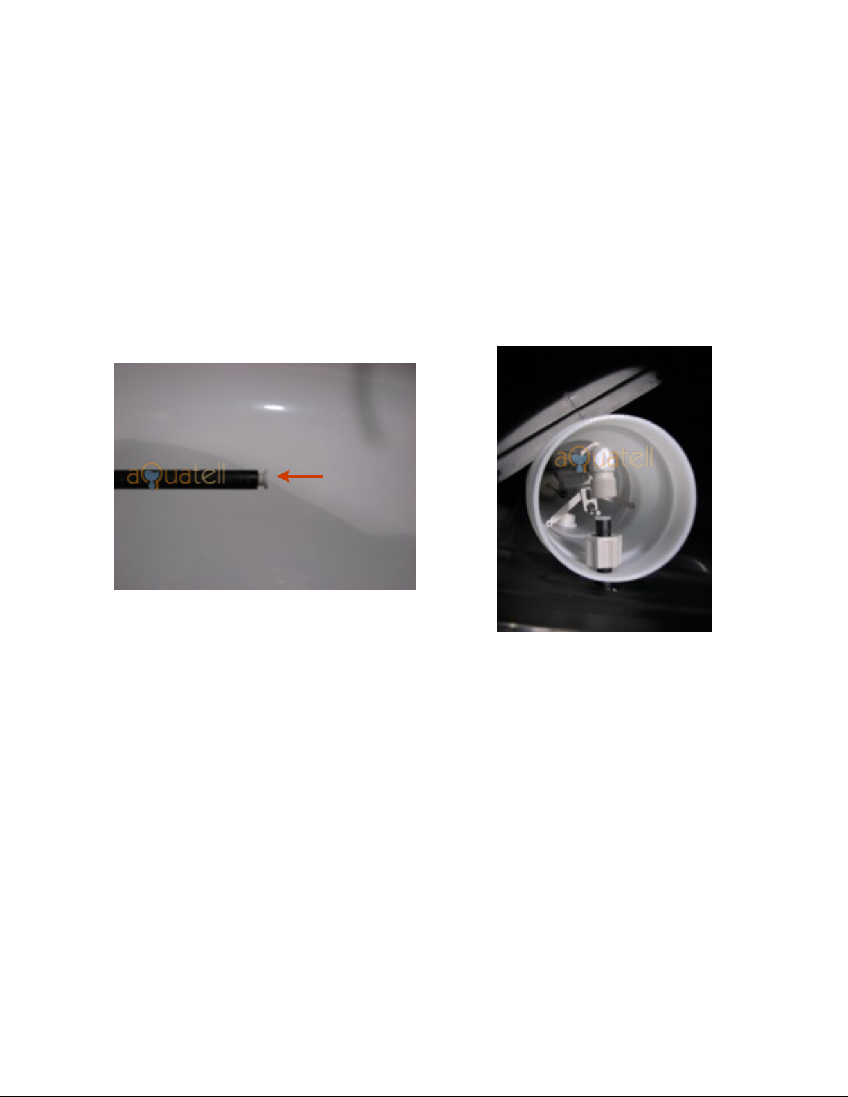
the desired location. Insert the riser tube into this tank so that the slotted basket is at the bottom
of the softening tank. At the open end of the riser tube cover the opening with a piece of tape.
Now place the funnel in the opening of the softening tank and add the resin:
Page 3
Fleck 5600SXT U.S. V1.1
Copyright aQuatell Inc 2010
Once all of the resin has been added it is very important to remove the piece of tape from the top
of the riser tube.
Next, secure the upper media screen to the bottom of the water softener valve. The upper media
screen is a about three inches in length and is cylinder shaped. Depending on the type of
softener you ordered, the media screen may be white, black, or red:
There is an opening on both ends of the upper media screen. With the larger opening facing the
underside of the softener valve, press and turn the upper media screen so that it locks into place.
Once this is complete, ensure that the top lip and the threads of the softening tank are free from
resin. Apply a small amount of silicone lubricant (vegetable oil can be substituted) to the top
surface of the threads of the softening tank, to the o-ring on the underside of the softener valve,
and to the outer side of the top of the riser tube.
Lower the softener valve onto the softening tank making sure that the riser tube passes through
the upper media screen. Once the valve is lowered onto the tank, turn the valve in a clockwise
direction (as viewed from above). It is very important to exert force only on the valve and not on
the controller (at the front of the valve) during this step. Continue turning the valve until some
Page 4
Fleck 5600SXT U.S. V1.1
Copyright aQuatell Inc 2010
resistance is met and then give the valve another 1/12th turn. Because the valve is o-ring sealed
to the tank, the valve does not need to be over-tightened. Over-tightening can cause the o-ring to
become deformed and this can cause immediate or future leaking.
Putting it all together - The Brine Tank
If you received a softener that is 32,000 grains or less, the brine well (4” diameter white tube)
will be attached to the side of the brine tank already. If you received a softener larger than
32,000 grains you will need to attach the brine well to the side of the brine tank as follows:
1. Remove the lid from the brine well (4” diameter white
tube)
2. Carefully remove the float assembly from the inside of
the brine well.
3. Looking from the top (down the brine well), identify the
hole in the side of the brine well
4. Looking at the side of the brine tank (usually black) you
will see two holes.
5. Working from the outside of the brine tank pass the
threaded end of the overflow bulkhead fitting pictured
left through the bottom hole in the brine tank and
through the hole in the side of the brine well. Secure the
fitting (and the brine well) by attaching and tightening
the nut from the inside of the brine well.
6. The brine well should now be secured to the side of the
brine tank.
7. Attach a drain line to the barbed end of the bulkhead
fitting and run this to a floor drain.
Page 5
Fleck 5600SXT U.S. V1.1
Copyright aQuatell Inc 2010
Putting it all together - The Float Assembly
If you haven’t done so already, remove the lid from the brine well and carefully remove the float
assembly. You can do this by holding the elbow with the grey plastic hex nut and slowly pulling
this upwards. The float assembly is delicate, so proceed carefully. Once it’s removed it will look
like this:
The float assembly controls the flow of brine solution out of the brine tank, and the flow of fresh
water into the brine tank. On the thin vertical bar of the float assembly identify the two black
rubber washers. These washers control the range of motion of the cup-shaped float.
Ensure that the top washer is about 3” below the top standoff and about two inches above the
bottom standoff. When these rubber washers are positioned properly the float will hit the top
washer before the brine tank water level gets to the brine tank overflow (the same piece that
holds the brine well to the brine tank)
The next step is to unscrew the hex nut from the top of the float assembly (see orange arrow
above). Once the hex nut is removed you will see a small tube insert inside. Remove the tube
insert and keep it and the hex nut aside then carefully lower the float assembly back down into
the brine well.
Page 6
Fleck 5600SXT U.S. V1.1
Copyright aQuatell Inc 2010
3”
Putting it all together - Attaching the Brine Line to the Brine Tank
The brine line (thin black plastic tubing) connects the water softener to the brine tank. At
different stages of the softener regeneration process it carries brine solution from the brine tank
to the softener and it also carries fresh water from the softener to the brine tank. This tubing
needs to be attached to the brine tank and the softener.
In a previous step you unscrewed the hex nut of the overflow assembly and set aside the tube
insert. Install the tube insert on one end of the brine line and then install this on the overflow
assembly as pictured below:
To attach the brine line to the brine tank you will first insert the tube insert into one end of the
brine line. Be sure to push it all the way in. Then pass this end of the brine line through the
upper hole in the brine tank and through into the brine well. Slide the hex nut onto the brine line
and then insert the brine line fully into the threaded elbow of the brine float. Now tighten down
the hex nut until it is snug making sure that the brine line is held firmly in place.
If the float assembly did not come with a tube insert, but instead has two small plastic rings,
place the plastic rings on the brine line instead of the tube insert. All other steps are the same.
Page 7
Fleck 5600SXT U.S. V1.1
Copyright aQuatell Inc 2010
push
Putting it all together - Attaching the Brine Line to the Valve
The brine line connector on the Fleck valve is made of brass and located on the side of the valve.
It can be identified on the picture below.
With your softener hardware you will find a small plastic bag containing the hardware you need
to connect the brine line to the brine line connector on the valve. There are four small pieces in
the bag that need to be attached to brine line as in the picture below:
The brass tube insert and woven metal insert must both be pushed fully into the brine line. Once
all the pieces have been attached to the brine line push it into the brine line adapter on the valve,
and tighten down the brass nut to hold it in place. After completing this make sure that during
the process of attaching the brine line to the valve, that the brine tank connection did not loosen.
Putting it all together - Attaching the Drain Line to the Valve
The drain line port on the Fleck is located at the rear of the valve. Included in your pack of
hardware is a grey drain line barb that is threaded on one end (see orange arrow below). Screw
Page 8
Fleck 5600SXT U.S. V1.1
Copyright aQuatell Inc 2010
this drain line adapter into the port. Some softeners will ship with a straight drain line adapter
and some will ship with a 90 degree adapter. On some softeners it is necessary to remove the
turbine assembly before screwing in the drain line barb. The turbine assembly is easily removed
by first removing the steel holding clips on either side of the bypass assembly (see blue arrow
below):
Prepare the drain line barb by applying three or four passes of teflon tape on the threads.
Unscrew the clips shown with the blue arrow and then remove the turbine assembly by pulling
firmly. Wiggling it back a forth gently may help. Do not pull the turbine assembly too far from
the valve as you may pull out the grey wire that connects the turbine assembly to the valve.
Once the turbine assembly has been removed, attach the drain line barb and then re-attach the
turbine assembly by fastening the steel clips that were removed earlier.
Flexible tubing with an inner diameter of 1/2” is usually used for the drain line. This can be
secured to the drain line barb with a small gear clamp (not included). The drain line can be
routed to a floor drain, utility tub, drain stem, or can be sent to the outdoors. Be sure to abide by
all local plumbing codes when deciding on the drain location. The open end of the drain line
needs to be secured as it will move when water is flowing through it.
Putting it all together - Installing the Bypass Valve & Plumbing Adapters
The bypass valve is a set of on/off valves that sit between your softener valve and your
plumbing. The role of the bypass valve is two-fold. It offers an easier way to connect your
existing plumbing to your softener and it also provides a way to bypass the water softener. The
bypass functionality is helpful if you ever need to make a repair to your softener - you can do so
without having to interrupt the water flow to your home.
Page 9
Fleck 5600SXT U.S. V1.1
Copyright aQuatell Inc 2010
With any water softener installation it is very important that all incoming and outgoing plumbing
is supported. The bypass should not support any of the weight of the plumbing as this will often
cause leaks or premature failure of the bypass. The plumbing can be supported by affixing it to a
wall. It is also important that incoming and outgoing plumbing is lined up properly with the
bypass. If plumbing is brought in on an angle, or if the plumbing exerts any sideward pressure
on the bypass valve, it will often cause a leak.
There are two bypass options for the Fleck valve as pictured below:
The plastic bypass comes in two pieces: the bypass and the plumbing adapter. The plumbing
adapter will be 3/4’ or 1” threads as ordered. The first step in the installation of the plastic
bypass is to attach the bypass valve to the plumbing adapter. This is accomplished by pushing
the two pieces together and tightening the metal clips on the side (orange arrow above).
Both the plastic bypass/adapter and the stainless steel bypass are attached to the Fleck valve in
the same fashion:
Page 10
Fleck 5600SXT U.S. V1.1
Copyright aQuatell Inc 2010