Aquathin ASC25K/F User manual

© 2007-2013 Aquathin Corporation. All rights reserved.
Includes setup and maintenance information for:
Aquathin Soft&Clean system
Getting Started With
Your
Aquathin
SOFT & CLEAN SYSTEM
Models ASC25K/F, ASC40K/F, ASC45K/F,
ASC60K/F
(In full color at www.aquathin.com)
AN ISO 9001:2008 QMS
REGISTERED /CERTIFIED COMPANY
(IMS-0192 & NQA-12635)

2 © 2007-2013 Aquathin Corporation. All rights reserved.
Under the copyright laws, this manual may not be copied,
in whole or in part, without the written consent of
Aquathin Corporation.
Every effort has been made to ensure that the information
in this manual is accurate. Aquathin Corporation is not
responsible for printing or clerical errors.
Aquathin Corporation
Aquathin Business Centre
950 South Andrews Avenue
Pompano Beach, Florida 33069
1-800-GO.2.RODI (462-7634) or 1-954-781-7777
Fax: 1-954-781-7336
www.aquathin.com
Aquathin Corporation, the Aquathin Corporation logo,
MegaChar—BFF Water Conditioning System,
Soft&Clean Water Conditioner are trademarks and
copyright of Aquathin Corporation. Product
specifications are subject to change without notice.
Your Authorized Aquathin Dealer Is:
Dealer Name___________________________________
Contact _______________________________________
Address _______________________________________
_______________________________________
Phone _______________________________________
Fax _______________________________________
Email _______________________________________

3 © 2007-2013 Aquathin Corporation. All rights reserved.
Introduction
Thank You for your purchase. Aquathin turned
"30 in 2010" to enjoy its Pearl Anniversary and
it’s a great feeling of self satisfaction and accom-
plishment to be an Authorized Aquathin Dealer. You
could not have picked a better time to consider the
many benefits of becoming a member of the ever
growing Aquathin Family. The Next Quarter Century
Celebration Begins!
Aquathin manufactures a broad spectrum of unique
and patented water purification, softening and filtra-
tion systems servicing the residential, commercial
and laboratory markets. Established in 1980,
Aquathin now produces over 70 patented and trade-
marked devices for markets around the world
through more than 600 Authorized Aquathin Deal-
ers. Aquathin is an E.P.A. Registered manufacturer,
ISO 9001:2008 Certified and recipient of the prestig-
ious President's Excellence Award in Export from
the U.S. Commerce Department and the Nation's
Blue Chip Enterprise Initiative Award from the U.S.
Chamber of Commerce. We have a very impressive
global client list that now includes you and your fam-
ily. Recently we have launched a project, two years
in the making, for Authorized Aquathin Dealers to
provide total home air and water security...and
more. Visit the Aquathin Allergy Store online at
www.aquathin.com.

4 © 2007-2013 Aquathin Corporation. All rights reserved.
Aquathin does not sell franchises nor do we charge
for territories. We want to make sure that our Deal-
ers are service oriented and knowledge driven. We
know that even though we make the best water
treatment systems in the world, ultimately they are
only as good as the people representing them. And
this is why we make the very best water treatment
Dealers in world. Your local Authorized Aquathin
Dealer has received training and continuous educa-
tion from Aquathin University. You can be assured
that when you purchase from an Authorized
Aquathin Dealer (or from the factory directly in areas
where we have yet to approve and establish a
Dealer) you are receiving the finest equipment and
technical support this industry is able to offer. High-
est quality water treatment systems and support
good enough for my home...my family.
And that is my promise to you! I love my Aquathin!!
FOR THE BEST TASTE IN LIFE &
30 Years Pure Excellence
...and another Quarter Century re-inventing the water industry!
Think Aquathin...AquathinK !!
( visit the NEW www.aquathin.com )
"Alfie"
Alfred J. Lipshultz, President
P.S. Remember...the next best thing to owning an
Aquathin is recommending one to a friend!

5 © 2007-2013 Aquathin Corporation. All rights reserved.
C o n t e n t s
1Getting Started 7
Setting Up Your System 8
1.Unpack the System 10
2. Required Tools 11
3. Planning the Installation 11
4. Connect Control Valve to Resin Tank 12
5. Prepare Connection to Water Source 13
6. Connect Water Source to Bypass Valve 13
7. Identify Water Inlet and Outlet 15
8. Connect Cable to Meter Assembly 16
9. Connect to Drain Valve 16
10. Connect Brine Line Flow Control 16
Verify the Tubing and connections 17
1. Check Bypass Connections 17
2. Check Flow to Resin Tank 17
3. Check Drain Line 17
4. Check Flow to Brine Tank 18
Starting Your System 18
1. Plug the Unit to an Electrical Outlet 18
2. Set Water Usage Program 18
3. Add Salt to Salt Tank 20
4. Set Regeneration Knob 20
2
Getting to Know the Aquathin System 21
A Look at the Key Components 21
Manual Regeneration Knob 21
24-Hour Gear 22
Program Wheel 22
Meter Assembly 22
Clip Cabinet 23
Operating Parameters 23
Pressure 23
pH 23
Chlorine and Chloramines 23
Sediment 24

6 © 2007-2013 Aquathin Corporation. All rights reserved.
Iron 24
Hardness and More 24
3
Maintenance And Servicing 26
Monthly Salt Replacement 26
Reset Time if there is Power Interruption 27
Exterior Cleaning 27
Options 27
4
Frequently Asked Questions 28
5
Limited Warranty 32
What The Warranty Covers 32
Exceptions To Warranty 32
Extending to Lifetime Warranty 33
What We Will Do To Correct An Inconvenience 33
How State Law Relates To The Warranty 33
A
ppendix A - Specifications 34
A
ppendix B –Installation Diagrams 35

7 © 2007-2013 Aquathin Corporation. All rights reserved.
GETTING STARTED
Thank you for purchasing this quality water conditioning
and softening system by Aquathin Corporation. The
SOFT & CLEAN Water Conditioning Series is a com-
pact, total home water protection system for the removal
of calcium, magnesium (which are hard water constitu-
ents) and up to 5 parts per million of iron. The exclusive
Aquathin SOFT & CLEAN system can also treat tannins,
nitrates and colloidal silica. Please consult with your local
Authorized Aquathin Dealer regarding these options.
The SOFT & CLEAN system allows a remarkable flow
rate of up to 20 gallons per minute; it saves up to 50% on
salt; it saves water and reduces sewerage taxes as well.
The advanced technology of the system allows it to moni-
tor water usage even during power failure and the system
initiates regeneration only when needed.
As the new owner of an Aquathin RO/DI water condi-
tioning system there is a totally new experience awaiting
you. Showers and baths will feel cleaner and fresher.
Laundry and dishes will be brighter and spot free.
This manual provides information about the application
and servicing of your Aquathin water softening system.
Descriptions of the components and their functions will
help to answer frequently asked questions. By thoroughly

8 © 2007-2013 Aquathin Corporation. All rights reserved.
reading this manual you will be better able to operate
your new system and perform simple maintenance.
SETTING UP YOUR SYSTEM
Your Aquathin system requires adequate water pressure;
a minimum of 25 PSI (pounds per square inch) of water
pressure is required for the regeneration valve to operate
effectively. The amount of conditioned water produced
depends primarily on your source water hardness and
capacity. Installation to comply with state and local laws
and regulations.
As the Soft&Clean water conditioner system will be in-
stalled on existing plumbing sources; it is important to
ensure that the condition of the existing plumbing is free
from lime and iron buildup. Replace piping that has
heavy lime and/or iron buildup. If piping is clogged with
iron, consult with your local authorized Aquathin Dealer
regarding a separate iron filter unit ahead of the water
softener.
The Aquathin Soft&Clean system requires an uninter-
rupted alternating current (A/C) supply. Please make sure
that the voltage supply is compatible with the unit before
installation. (110V/60Hz or 220V/50Hz for international)
IMPORTANT NOTE:
While installing the Soft-&Clean system, please follow this
cautionary note:
This system is to be supplied with cold water only.
Do not exceed 120 PSI (8.5 bar) water pressure.
Do not exceed 110º F (43º C) water temperature.
Do not subject the unit to freezing conditions.
This system is not intended to be used for treating water
that is microbiologically unsafe or of unknown quality
without adequate disinfection before the system

9 © 2007-2013 Aquathin Corporation. All rights reserved.
Installing Your System Requires the Following
Steps:
Identify suitable location for the unit, preferably
near a clean working drain—the location should be
swept clean before the unit is positioned to avoid
tank puncture.
Perform all plumbing according to local plumbing
codes.
Turn off the main water supply valve.
Turn off the power source for the electric water
heater, or if gas, turn the heat control to pilot.
Relieve water pressure by opening any cold water
faucet before cutting the water line to make the
installation.
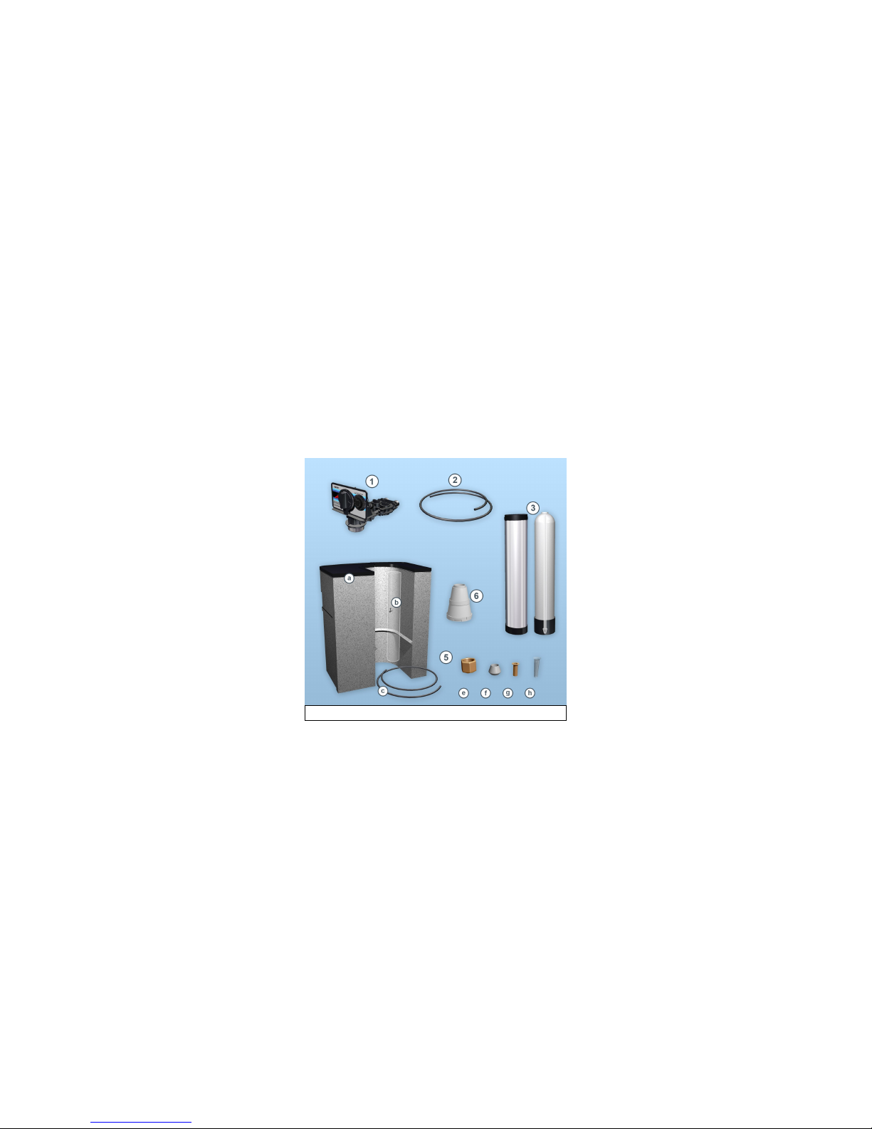
Solder pipes to adaptors, which will be screwed
into the bypass valve.
Screw adaptors into the bypass valve before mount-
ing the bypass valve onto the resin tank.
Lubricate the distributor o-ring seal and tank o-ring
seal. Place the main control valve on tank.
Wrap a wet rag around the bypass valve to prevent
internal damage by heat transfer as you proceed
with soldering.
NOTE: the water outlet is on the left side of the
unit—you will notice that an arrow indicates the
outlet—showing water flow away from the unit;
whereas if you stand in front of the unit, the inlet is
on your right side.
Put approximately 1” of water in the salt tank.
Turn on the water supply.
Place the bypass valve in Bypass position and
check for leaks.
Connect the drain line flow control fitting.
Plug the unit into an electrical outlet.
Set time of day and water hardness.

10 © 2007-2013 Aquathin Corporation. All rights reserved.
1. Unpack the System
Contents include:
1. Main control valve
2. Drain line
3. Resin tank (with chrome jacket and distributor
tube)
4. Patented Clip CabinetTM with:
a) built-in salt storage tank
b) built-in Safety Float Assembly and brine well
c) tubing
5. Brine line fitting components:
e) fitting nut
f) ferrule
g) tube insert
h) brine line screen
6. Upper basket
Figure 1. Package Contents

11 © 2007-2013 Aquathin Corporation. All rights reserved.
2. Required Tools
While installing the unit, you will need:
Silicone lubricant and Teflon tape for the fittings.
Other tools and pipes may be required by the installer for
soldering and cutting while fitting the unit to the water
source and drain line.
The SOFT & CLEAN System requires water softener
salt specifically manufactured for water softeners.
3. Planning the Installation
Review the following instructions completely before pro-
ceeding. (See installation diagram in Appendix B) The
Aquathin SOFT & CLEAN System is a unique two-tank
design in a single footprint that fits easily in compact
spaces.
1) Warm the valve to room temperature during cold
weather
During cold weather it is recommended that the installer
warm the main control valve to room temperature before
operating.
2) Select and prepare the location
We encourage you to establish the desired location of
each of the components before proceeding. It is recom-
mended that you install the unit near a clean and working
drain.
Be sure that the area where the SOFT & CLEAN system
will be installed is swept clean before the unit is posi-
tioned for installing to avoid puncture of the storage tank.

12 © 2007-2013 Aquathin Corporation. All rights reserved.
If installed outdoors, put down plywood or a concrete
stone in order to provide a flat, even surface for the
SOFT & CLEAN system to be placed upon. (CAUTION:
this unit will crack if allowed to freeze).
4. Connecting the Control Valve to the Resin
Tank
1) Lubricate the
distributor o-ring
located by the
control valve
throat as shown
in figure 2.
2) Lubricate the
tank o-ring seal,
as shown in fig-
ure 3. NOTE: use
only silicone lu-
bricant.
3) Attach the pro-
vided upper bas-
ket (bayonet fit)
to the control
valve as shown in
figure 4.
Fig. 2. Lubricate distributor o-ring
with silicone lubricant.
Fig. 3. Lubricate the tank o-ring.
Fig. 4. Make sure the upper basket
locks into place.

13 © 2007-2013 Aquathin Corporation. All rights reserved.
4) Screw the con-
trol valve on the
resin tank—
turning it clock-
wise (figure 5).
5. Preparing Connection to Water Source
1) Turn off the main water supply valve for your resi-
dence / company.
2) Turn off power source for electric water heater.
If the water source is connected to an electric water
heater, turn it off. In the case that it is connected to a gas
heater, turn the heat control to pilot. If a shut-off valve is
provided on the inlet side of the water heater, close that
during the SOFT & CLEAN System installation.
3) Relieve water pressure
Relieve water pressure by opening up any cold water fau-
cet before cutting the water line to make the installation.
6. Connecting Water Source to Bypass Valve
As the SOFT & CLEAN water softening system will be
installed on existing plumbing sources, it is important to
ensure that the condition of the existing plumbing is free
from lime and iron buildup.
Replace piping that has heavy lime and/or iron buildup.
Fig. 5. While screwing the valve
onto the resin tank, make sure the
distributor tube locks into place.

14 © 2007-2013 Aquathin Corporation. All rights reserved.
If piping is clogged with iron, install a separate iron filter
unit ahead of the water softener system.
1) Unscrew the bypass
valve
Unscrew the bypass
valve from the main
control valve of the unit
as shown in figure 6.
2) Solder pipes to
adaptors
According to your local
plumbing codes, the
installer must identify
appropriate pipes to be
connected to the bypass
valve.
The pipes must be first
soldered onto the adap-
tors as shown in figure
7.
3) Screw adaptors into
bypass valve
The adaptors can then
be screwed onto the
bypass valve as shown
in figure 8.
4) Re-attach the by-
pass valve
Attach the bypass valve onto the main control valve using
Fig. 6. Unscrew the bypass valve,
and remove the adaptor clips.
Fig. 7. Solder the pipes to the
adaptors.
Fig. 8. Screw the adaptors back
on the bypass valve.

15 © 2007-2013 Aquathin Corporation. All rights reserved.
the provided clips and
tighten the screws as
shown in figure 9.
Doing so, you will be
able to measure and ap-
proximate the required
length of piping from the
bypass valve to the water
source and outlet.
5) Solder joints with caution
Wrap a wet rag around the bypass valve to prevent inter-
nal damage by heat transfer as you proceed with solder-
ing. It is recommended that you leave at least
6” (152mm) between the bypass valve and solder joints
when soldering pipes that are connected on the bypass
valve. Failure to do this can cause interior damage to the
bypass valve.
7. Identifying Water Inlet vs. Outlet
As you stand in front of
the unit, the inlet is on
your right, while the out-
let is on the left. Alterna-
tively, you can look for
the arrow near the bypass
valve outlet indicating
away from the unit, as
shown in figure 10.
Fig. 9. re-attach the bypass
valve to the main control valve.
Fig. 10. The arrows on the by-
pass valve (as shown) indicate
water inlet and outlet.

16 © 2007-2013 Aquathin Corporation. All rights reserved.
8. Connecting the Cable to the Meter Assembly
Connect the cable from the
control valve to the meter
assembly as shown in figure
11.
The meter assembly of the
SOFT & CLEAN water
conditioning system is sim-
ple and dependable as it
mechanically monitors water usage even during power
failure and initiates regeneration only when needed.
9. Connecting to Drain
Valve
Connect the 5/8 inch black tube
provided to the drain hose barb
as shown in figure 12.
10. Connecting the Brine Line Flow Control
In order to connect the brine line from the patented Clip
CabinetTM to the main control valve, use the brine line
fittings provided:
a) fitting nut
b) ferrule
c) tube insert
d) brine line screen
Fig. 11. Firmly insert the
cable in the meter as shown.
Fig. 12. Connect the
drain line as shown
Fig. 13. Place the nut and the
sleeve on the tube, followed by
the tube insert and screen as
shown.
Fig. 14. With the brine fittings
in place, screw the brine line to
the main control valve as
shown.

17 © 2007-2013 Aquathin Corporation. All rights reserved.
VERIFYING THE TUBING AND CONNECTIONS
1. Check Bypass Connections
Once plumbing is completed,
with the bypass/service knob in
the “bypass” position as shown
in figure 15, open the main wa-
ter supply valve and check for
leaks in the bypass connection.
Open a cold water tap nearby
and let water run for a few min-
utes or until the system is free
of foreign materials (usually solder resulting from the
installation). Close the water tap when water runs clean.
If there are no leaks, open the inlet valve to the water
heater and restore power or gas setting on the water
heater.
2. Check the Flow to the
Resin Tank
Slowly move the bypass/
service knob in “service”
position and let water flow
into the mineral tank. This is
an indication that the unit has
purged itself of all air. See
figure 16.
3. Check the Drain Line
With the regeneration knob already in “service” position,
now rotate the knob clockwise into “backwash” position
Fig. 15. turn the bypass
knobs perpendicular to
the valve in order to
“close” it, as shown.
closed
open
Fig. 16. turn the bypass
knobs parallel to the valve
in order to “open” it, as
shown.

18 © 2007-2013 Aquathin Corporation. All rights reserved.
(as shown in figure 17) and
allow water to flow at the
drain for 3 or 4 minutes.
4. Check Flow to the
Brine Tank
Manually index the regen-
eration knob to the “brine
fill” position” and allow the
brine tank to fill to the top
of the air check. See figure
18.
Then manually index the
control knob to the “brine
rinse” position and allow
the control to draw water
from the brine tank until it stops.
STARTING YOUR SYSTEM
1. Plugging the unit into an electrical outlet
Once the installations are completed and you have veri-
fied the tubing and connections, you may plug the system
into an approved power source.
2. Setting the Water Usage Program
To program your SOFT & CLEAN system, first you
must set the time on the unit.
1) To set the time on the unit, refer to figure 19 and
take the following steps:
First push in the red “time set button”
Then rotate the 24-Hour Gear so that the “time of
Fig. 17. Rotate the regenera-
tion knob until in
“backwash” position
Fig. 18. Rotate the knob to
“brine refill” position

19 © 2007-2013 Aquathin Corporation. All rights reserved.
day” indicator
shows the cur-
rent local time
(i.e. if it is 2 pm
your time, the
“time of day”
indicator should
point to “2p”)
When you re-
lease the gear,
check for firm
engagement of
the setting
(indicated by a
clicking sound).
Next, the hardness must be set; this allows the unit to
monitor the system automatically and the system regener-
ates only when necessary.
2) For typical residential application, refer to figure 20
and take the following steps in order to set the hardness:
Rotate the pro-
gram wheel so
that the white
dot on the wheel
is aligned to the
black arrow
Lift and rotate
the gallons
wheel so that the
number of gal-
lons is aligned
with the black
arrow and white
dot.
Check for firm engagement at setting.
2 p
c. Time of day
a. Push button
b. Rotate gear
Fig. 19. (a) push the red button,
(b) rotate the gear which is behind
the regeneration knob
(c) rotate the gear till the time
shown is the same as your local
time
Fig. 20. (a) rotate program wheel to
align white dot with black arrow,
(b) lift and rotate gallons wheel to
align gallons with black arrow
a. Rotate program wheel
b. Lift and rotate
gallons wheel

20 © 2007-2013 Aquathin Corporation. All rights reserved.
For calculating the number of
gallons, you may use the follow-
ing formula described below:
The model ASC45K has a
45,000 grains capacity. If your
source water has 25 grains per
gallon (gpg), then the gallon
capacity will be:
45,000 grains capacity / 25 gpg
= 1,800 gallons capacity.
In this case, align the white dot
and the number “18” on the gallons wheel to the black
arrow, as shown in figure 21.
Consult your local Aquathin Dealer for confirmation of
this setting and for water hardness testing.
3. Adding Salt to the Salt
Tank
Add salt to the salt tank up to the
level marked “FULL” on the out-
side of the tank. See figure 22.
Use only Water Softener Salt.
4. Setting the Regeneration
Knob
Manually advance the control
knob to the “regeneration” posi-
tion and allow the control to return to the “in service”
position automatically (approximately 90 minutes). Do
not use household water until cycles are completed. This
will allow the resin tank to purge all air.
Fig. 21. Align black
arrow, white dot and
number of gallons (18
in this case)
FULL
Fig. 22. Fill salt until
the “FULL” level
marked on the salt
tank
This manual suits for next models
3
Table of contents
Popular Water Dispenser manuals by other brands

IBC Water
IBC Water AST0715MP-960 Installation & operating instructions

Lancaster Water Treatment
Lancaster Water Treatment X FACTOR LX15 Series Installation, operating and service manual

Elkay
Elkay EMABF8 Series Installation & use manual

Oasis
Oasis Osmosis Home installation manual

Monarch Water
Monarch Water ULTIMATE MINI AQUA HE install guide

Haier
Haier HLM-109B instruction manual