Aquatic AQ-AD300.2 User manual
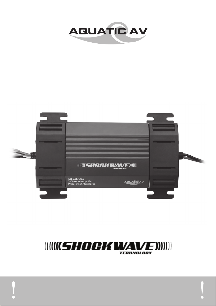
products with a watertight reputation
2 CHANNEL WATERPROOF AMPLIFIER
AQ-AD300.2
OWNERS MANUAL
PLEASE READ THIS INSTRUCTION MANUAL BEFORE INSTALLATION
AND OPERATION
2 CHANNEL WATERPROOF AMPLIFIER WITH
AQ-AD300.2

IMPORTANT INFORMATION
2
Please read these notes before you begin installation. We also strongly recom-
mend that you thoroughly read and understand the installation instructions
included.
Avoid over-driving your speakers
Follow the instructions given to properly set gain and frequency adjustments. If your
system conguration results in settings outside the typical range and something maybe
wrong, please contact your local Aquatic AV dealer or Aquatic AV Technical Support.
Check your battery and electrical system
Low battery conditions and poor electrical systems should be diagnosed and corrected
before installing your amplier. Old batteries may be good enough to start your engine
but may not be up to the task of powering a high output audio system. Running your
amplier in a low-voltage situation can cause premature distortion, fuse blowout, and
system shutdown.
Ensure proper power and ground connections
Never connect or disconnect the control cables with the ampler(s) powered on.
Always disconnect your battery before working with your electrical system, and keep it
disconnected until you are ready to test.
Cover all exposed wires to avoid shorts.
Make your power and ground connections exactly as the instructions specify.
www.aquaticav.com

IMPORTANT INFORMATION
3
www.aquaticav.com
AQ-AD300.2
USING YOUR AMPLIFIER
Working safely with your battery
Disconnect the negative battery terminal before doing any electrical work. Always
disconnect the negative (–) battery post rst, followed by the positive (+), and when it’s
time to go back together, connect the positive (+) post rst, followed by the negative
(–). This can minimize the chance of sparks and voltage spikes, and is a good general
practice when dealing with any DC electrical system.
Grounding
Bad grounds under are the number one cause of problem installs.
Always use the shortest length of ground wire possible between chassis ground and
the amplier. Never use a ground wire longer than the one we provide.
The ground wire and power wire are equally important; if either one of them is compro-
mised, the amplier’s performance will degrade or cease to function.
Fuses
Always install a master fuse within 12” of the battery for any additional equipment
added to your installations electrical system. The mini-fuse installed on the main ampli-
er only protects the internal circuitry, not the wiring. In the event of a short, failure to
install a fuse near the battery can cause damage to your electrical system or the pos-
sibility of re.
Speaker Polarity
The way speaker wires are marked for polarity (+/–) varies from brand to brand. Some
manufacturers use the stripe as positive (+), while others use the stripe as negative
(–). Be sure to check the documentation of each component you’re dealing with before
making connections.
Cutting Cables
Always route wires and cables safely, avoiding sharp edges and burrs along the way.
Use wire loom when possible. Check for proper length to both termination points,
knowing where each component mounts, before you cut anything.

GETTING STARTED
4
www.aquaticav.com
AQ-AD300.2
CONTENTS
• AQ-AD300.2 amplier x1
• Power cable x1
• 24” high level input cable x1
• Low level (RCA to Phono) input cable x1
• Owners Manual x1
SERIAL NUMBER
Please record the model and serial number[s] of your equipment in the space provided
below as your permanent record. These numbers can be found on the front and/or bot-
tom of each component. This will assist us with your factory warranty coverage.
TERMINOLOGY
Source unit: refers to the device that supplies the amplier with audio input, typically
your radio, head unit, media device, etc.
Main amplifier: AQ-AD300.2, master 2 channel amplier that functions standalone.
Remote turn-on wire: used to switch the amplier system on/off, usually controlled by
your ignition system, or by the remote lead of a source unit.
Low level input cable: used when rca connectors are the source of input to the ampli-
er.
High level input cable: used when speaker wires are the only source of input to the
amplier, typically used with a factory source unit.
Manufacturer instructions: refers to any documentation provided by a manufacturer
other than Aquatic AV.
Model number[s]: Serial number[s]:

GETTING STARTED
5
www.aquaticav.com
AQ-AD300.2
Keep an eye out for these symbols throughout this manual; they provide a visual link
between instructions, diagrams, and the system components.
QUICK CONNECT SYMBOLS
Power: Battery positive (+12vdc)
Ground: Battery negative (–), chassis ground
Remote: Remote turn-on lead activated by +12vdc
Fuse: Essential protection from shorts
Line-in: Source input, low level or high level input
Speaker: Terminal block connections for speaker output
Configure: Amplier conguration features (gain, crossovers, etc.)
SHOCKWAVE TECHNOLOGY™
Aquatic AV’s Shockwave Technology brings together outstanding sound qual-
ity, high performance characteristics and unprecedented reliability into a single
amplifier.
Protected against water and dust with an Ingress Protection rating of IP66 means you
can literally hose down our Shockwave Technology ampliers thanks to a number of
unique features exclusive to Aquatic AV (patents pending).
Conformal coated circuit boards protect the smallest components from any humidty or
atmospheric moisture, while custom molded grommets around cable extrusions and
gaskets between all meeting points eliminate any chance of water or dust intrusion.
Aluminium and Stainless Steel are used in chassis construction eliminating any risk of
rust or corrosion.
Designed to support the widest variety of applications, Shockwave Technology ampli-
ers operate both 4ohm and 2ohm speaker congurations, from either low-level (RCA)
or high-level (speaker) input connections.
Shockwave Technology incorporates Digital IC’s with specially designed low-noise
circuitry to produce high-quality, true sound reproduction from any source. The tech-
nology used also reduces unwanted EMI ( Electromagnetic Interference), which can
cause noise in your audio system. Using gold plated RCA’s and high quality connec-
tors ensures the best possible listening experience. Digital ampliers are much more
efcient than traditional ampliers; producing less heat, lowering power consumption,
reducing strain on batteries and charging systems.
Shockwave Technology ampliers combine all these features into a single compact unit
and when compared with the competition, still make considerable reductions in both
size and weight!
Aquatic AV’s Shockwave Technology is now the only sensible amplier solution for wet,
dusty or harsh environments.

INSTALLATION
6
www.aquaticav.com
AQ-AD300.2
3. Determine and connect your source unit output to the amplier input cable(s) using
one of the following high or low level input methods:
3.1. High Level input (no RCA connectors available) connect the front speaker output
wires from the source unit to the high level input cable (use attached terminals to con-
nect input wires to the speaker wire terminals if possible).
For custom wiring connections, we recommend crimp, solder, and heat shrink.
3.2. Low Level input (RCA connectors available) connect the front RCA output connec-
tors from the source unit to the low level input cable and input jack on the front of the
amplier.
Very little dielectric grease is needed to keep your connections corrosion free.
Very little moisture is needed to corrode contacts not covered with dielectric grease.
4. Plug the chosen input cable into the corresponding connector of the main amplier
labeled high or low accordingly.
WIRING THE AMPLIFIER
1. Route and connect the power wire (without the in-line fuse installed) from the posi-
tive (+) battery terminal to the main amplier terminal labeled PWR.
Do not install the in-line fuse until instructed to do so.
2. Route and connect the ground wire from chassis ground to the amplier terminal
labeled GND.
The majority of problem installs are the result of a poor ground. Refer to section
‘Ensure proper power and ground connections’ in the Important Information’
section for more information.
High Level Input Cables
2 Channel - use Front only
4 Channel - use both
Front Left + White
Front Left - White with Black strip
Front Right + Grey
Front Right - Grey with Black strip

INSTALLATION
7
www.aquaticav.com
AQ-AD300.2
5. Install 4 ohm or 2 ohm speakers of your choice, if they are not already installed.
6. Route and connect the speaker wires from each speaker of your system to the cor-
responding speaker output terminal block on the amplier (right/left).
Keep the polarities (+/–) of each wire pair correct between the amplifier(s) and
speakers.
7. Re-connect the positive (+) side of the battery, followed by the negative (-) side.
Do not install the in-line fuse until after this step. This is a good time to re-check
your connections before installing the fuse. Make sure that all control cables are
completely seated and latched in their respective connectors, and that power and
ground are properly connected to the main amplifier.
8. Install the 25 amp ATC fuse into the in-line fuse holder on the power wire.
9. Perform a basic system test, verifying that the amplier(s) power up (led on each
component should light) and that the speakers function properly. If not, proceed directly
to Troubleshooting in the User Guide section.
10. Congure, test, and tune your system by following the Test and Tune instructions
given in the User Guide section of this manual. When you’ve completed these instruc-
tions the installation is complete.
WIRING THE SPEAKERS
TESTING & TUNING THE SYSTEM

USER GUIDE
8
www.aquaticav.com
AQ-AD300.2
CONNECTORS & CONTROLS
The images below list the controls and connectors of the AQ-AD300.2 amplier.
High level input connector
This connector allows the amplier to use speaker outputs from a source unit as inputs
to the amplier.
Wire colors for the high level input cable(s):
Low level input connector
This connector allows the amplier to use industry standard RCA outputs from a
standard source unit as inputs to the amplier. This is the preferred method when RCA
outputs are available, and will produce the cleanest source signal to the amplier.
CONNECTORS DEFINED
We use industry standard 3.5mm headphone style jacks on the amplifier due to the space
constraints (2x 3.5mm phono-jacks are a lot smaller than 4x RCA jacks). Although we highly
recommend using the low level input cables we supply with the kit, technically you should be
able to utilize any standard RCA to Phono adapter cable found at your local electronic store to
make these connections.
High Level Input Cables
Left + White
Left - White with Black strip
Right + Grey
Right - Grey with Black strip
AINPUT GAIN ADJUST EAMPLIFIER PROTECTION FUSE ICROSSOVER FILTER ADJUST
BHIGH LEVEL INPUTS FPOWER & STATUS LED JCROSSOVER MODE SWITCH
CSPEAKER OUTPUTS GLOW LEVEL INPUT
DPOWER & GROUND TERMINALS HREMOTE TURN-ON TERMINALS
A
JI
B C
H
GFD E
USER GUIDE
9
www.aquaticav.com
AQ-AD300.2
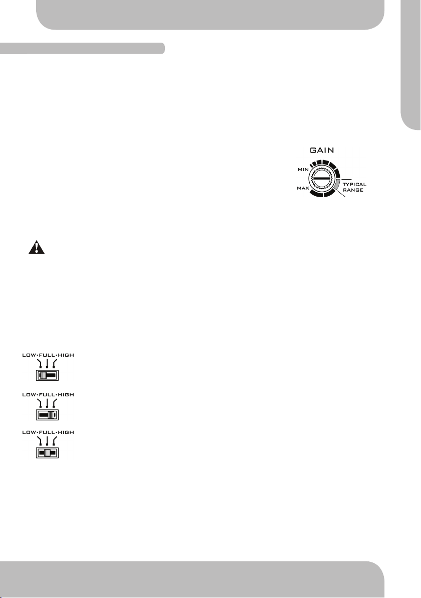
Input gain adjustment
A common misconception about gain adjustment on ampliers is that “more gain =
more volume”. Actually, it’s not the volume that’s being increased, but rather the ampli-
er’s sensitivity to the source input. By increasing the gain level, you’re increasing how
sensitive the amplier is to the signal it receives from the source unit. This is why it’s
important to set the gain properly, rather than simply turning the knob until it’s really
loud.
Gain allows the following nominal operating level adjustments:
Low level input (RCA line-in) - 250mv to 2.5V
High level input (speaker-in) - 500mv to 5V
These voltage levels can accommodate virtually any source unit, as well as just about
anything that has RCA or line-out style outputs.
Setting the gain too high in an attempt to get “more volume” can not only cause
premature distortion, but can also damage your speakers. If your system config
ration results in your gain control being set outside the typical range as indicated
above, call Aquatic AV to resolve the problem.
Crossover mode switch
This switch selects which range of frequencies that the built-in crossover will lter. Each
mode is equipped with 12dB per octave electronic lters for precise frequency attenua-
tion with minimal phase distortion. The options are as follows:
Low – low-pass – used when speaker outputs will drive subwoofers, or low
range speakers only.
High – high-pass (default) – used when speaker outputs will drive middle to
high range speakers only (recommended setting for full range speakers).
Full – full-range – used when speaker outputs will drive full range speakers
only. This by-passes and disables the crossover circuit. Note: changing the
crossover lter control will produce no effect in this mode.
CONNECTORS DEFINED (CONT.)

USER GUIDE
10
www.aquaticav.com
AQ-AD300.2
Crossover filter adjustment
The purpose of a crossover circuit is to lter out a specic range of frequencies from a
speaker’s input to maximize its performance. For a tweeter, the goal is to lter out low
(bass) range frequencies to maximize the high range (treble) response. Conversely,
for a subwoofer, the goal is to lter out the high and mid range frequencies, leaving
only low frequencies to play through the woofer. There are two kinds of crossover
implementations, active or passive:
Active Crossover
This lters selected frequencies before the audio signal is amplied, between the
source unit and amplier. Our built-in crossovers are an example of this type of crosso-
ver.
Pros:
By removing unwanted frequencies from the signal before it’s amplied, your output
becomes more efcient, only working to amplify the desired range of frequencies.
Cons:
By removing unwanted frequencies from the signal before it’s amplied, you are
dedicating those ltered channels to only provide a certain frequency range.
Passive Crossover
This lters selected frequencies after the audio signal has been amplied, between
the amplier and speaker. Some speakers are sold with passive crossovers included,
typically a small plastic enclosure, or capacitors and/or coils mounted directly to the
speaker.
Pros:
By removing unwanted frequencies from the signal after it’s amplied, your ampli-
er’s output is still full range, allowing more exible use, able to drive tweeters, mid-
range, and subwoofers alike.
Cons:
By removing unwanted frequencies from the signal after it’s amplied, you are forc-
ing the full range of frequencies to be amplied, reducing the amplier’s maximum
possible efciency.
Our built-in active crossover(s) are fully adjustable from 50hz to 250hz, using
either a low-pass mode (bass only) or high-pass mode (midrange and highs
only) to easily maximize your speaker’s potential.
Default: when using any 6.5” to 8” speakers, the
recommended settings are high pass mode with
the frequency lter set at or above 150hz.
CONNECTORS DEFINED (CONT.)
Table of contents
Other Aquatic Amplifier manuals


