User manual/ 2
INSTALLATION STEPS
1. Close the water supply.
2. Remove the pipe that led from the cap further into the pipe in the building.
3. Connect a softener between the supply and the pipe.
4. Remove the top cover from the device and connect the ByPass to the device from the back.
5. Before connecting the ByPass, apply silicone grease to the circumferential seal.
6. Then insert the ByPass into the back of the softener.
7. Attach the ByPass to the softener with a fastener that you screw on from the side. Do the same on the opposite side.
8. Apply silicone grease to the seal of the reducers, remove the red fuses from the ByPass and insert the reducers into the holes
at the end with the seal side facing the ByPass.
9. Then re-insert the red fuses. Bypass is now mounted on top of it you can see the red valves through which it is possible to
direct the ow of water.
10. Further connect the hose to the softener. It connects to the part where the ow sensor is inserted.
11. Remove this sensor and slide it into the sensor compartment.
12. Then slide the hose onto the outlet and pull it o with the Esca tape.
13. Connect the other end of the hose to the drain pipe.
14. Push the hose back on and tighten it with an Esca tape.
15. After you have successfully connected to the drain pipe, move the softener to a position where it will be stable.
16. Use stainless steel pipes to connect both the inlet and outlet. They can be easily shortened and bent as needed.
17. Connect the pipe to the water cap on the top and the inlet to the Bypass to soften the water.
18. Connect the second pipe to the pipe at the top and the Bypass outlet on the water softener.
19. Tighten all connections.
20. The water inlet is indicated by an arrow to the softener and the outlet by an arrow away from the softener.
21. After completing the assembly, simply pour the salt into the full tank, switch on the appliance to the mains and adjust the
control head.
22. The last step is to start the regeneration and slowly open the water supply. After regeneration, the device is ready for
operation. Finally, you can put the top cover back on. For the rst 24 hours, we recommend checking the tightness of all
connections.
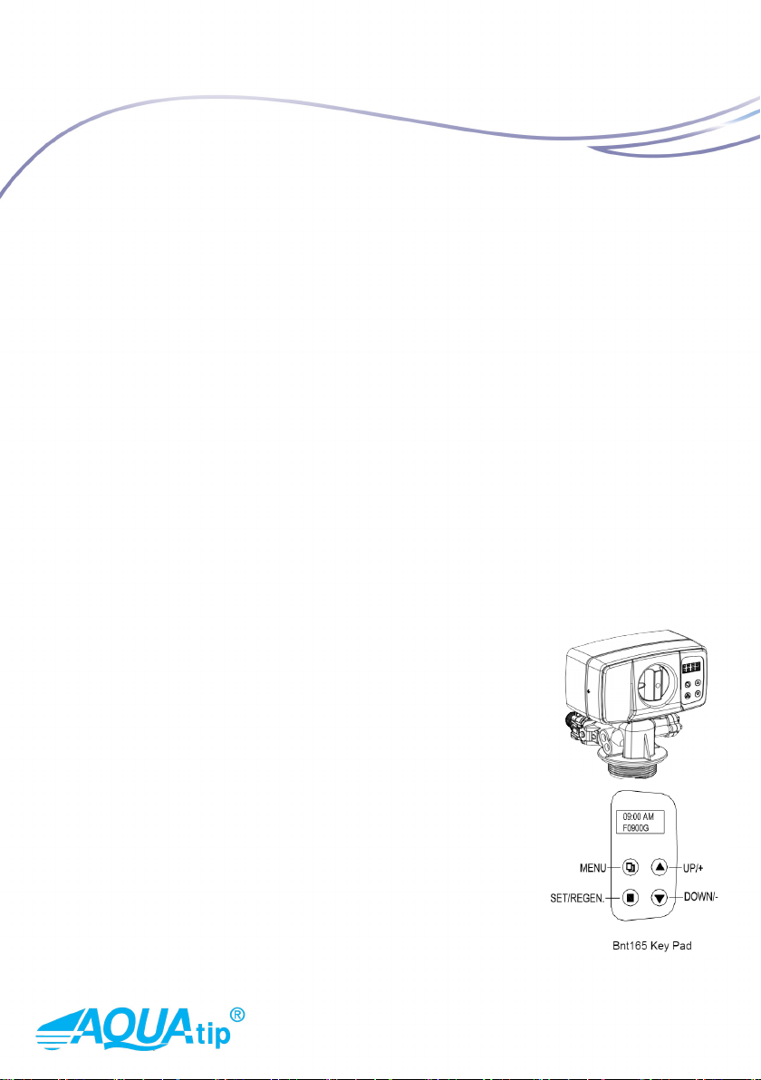
THE MAIN FUNCTIONS OF THE BNT 165
This valve is controlled by simple electronics, which are displayed on the LCD display.
The main display shows the current time. In addition, the following information is shown
on the display about softener: regeneration mode, remaining volume, time for regeneration.
Valve operation mode
1. Softener: standard water softener operation.
2. Filter: Automatic backwash lters such as Multi-Media Depth or carbon lter.
Regeneration mode
1. Timer
2. Meter immediate
3. Meter delayed
4. Mix regeneration
Equipment regeneration
Water hardness can be set - the user has the option to set the resulting water hardness by
mixing water (depending on the type of softener). EU Metric or US mode is available.
There are three preset mode settings:
1. High capacity mode (L.CAPA.) For large tank.
2. Medium Capacity Mode (M.CAPA) for medium size tank.
3. Low capacity mode (S.CAPA) for small tank.
Water softener AQUATIP AQ® BNT 8