AquaTools AT5800 User manual

AUTOMATIC POOL CLEANER
O W N E R’ S M A N U A L
OPERATION, TROUBLESHOOTING & PARTS
AquaTools
293 Wright Street, Delavan, WI 53115
International: 262-728-5551, FAX: 262-728-7550
©2003, AquaTools Printed in U.S.A. AT364 (Rev. 5/7/03)
ABOUT SAFETY
•Before installing the cleaner, review and
understand all warnings and safety information
on inside cover of manual.
ABOUT INSTALLATION
•Please use the convenient, water resistant
Installation Instructions card.
INDEX
About Safety .............................................................2
About Your Pool and Filter System ...........................2
About Installation .....................................................3
About the Cleaner Operation....................................4
About ”Fine Tuning” Vacuum Adjustments............4,5
About the Cleaner and Accessories...........................6
About Troubleshooting .............................................7
About Disassembly ...................................................8
About Assembly........................................................9
Repair Parts.............................................................10
About Maintenance ................................................11
Warranty.................................................................12
1873 0795
Model AT5800

2
Before installing your cleaner, review and
understand all warnings and safety informa-
tion on the inside front cover of this manual.
Pre-installation check list
Before installing the cleaner in a vinyl liner pool:
Check liner closely for signs of deterioration or damage
from age, chemicals, pool wall damage, etc. If any dam-
age is found, have a qualified pool professional make
all necessary repairs. Also, if there are stones, roots,
etc., under the liner, remove them before installing the
cleaner.
Before installing the cleaner in a gunite pool or a pool
that is partially or completely tiled:
Repair loose tiles and tighten any loose light rings.
Before installing the cleaner, clean your filter system:
Make sure you have cleaned the filter, including back-
washing, rinsing, and emptying all baskets. A clean
system is necessary for proper cleaner operation and
coverage.
Before installing the cleaner, fill the hose with water:
Always make sure the cleaner head is submerged and
the hose is full of water before connecting the hose to
the filtration system (whether through a skimmer or
dedicated wall fitting). Air in the system can damage
the pump through dry running and overheating.
Before installing the cleaner, understand cleaner cov-
erage:
The cleaner is designed to rid your pool of debris in
approximately 4-6 hours. Less time could be needed,
depending on the pool size.
The cleaner was not designed to automatically clean
steps or swimouts or to work under a solar cover. It
was also not designed to do initial cleanup for a new
pool or when opening your pool for the season.
Suction entrapment, injury, and drown-
ing hazard. If your pool has a dedicated suction
port (“vac port”) for vacuuming or for an automatic
pool cleaner, it must be covered when not in use.
A spring loaded safety cover is included with your
cleaner. Install it on the suction port to prevent
entrapment and injury.
ABOUT YOUR POOL AND FILTER SYSTEM:
This is the safety alert symbol. When you see
this symbol on your system or in this manual,
look for one of the following signal words and be
alert to the potential for personal injury.
warns about hazards that will cause
death, serious personal injury, or major property
damage if ignored.
warns about hazards that can cause
death, serious personal injury, or major property
damage if ignored.
warns about hazards that will or can
cause minor personal injury or property damage if
ignored.
Carefully read and follow all safety instructions in
this manual and on equipment. Keep safety labels in
good condition; replace if missing or damaged.
Hazardous suction.
Can trap and tear
hair or body parts.
Can cause drowning.
Do not play with cleaner
or hose or apply to body.
Do not let children use or
play with pool cleaner.
Stop pump before
attempting to clean unit.
1058 0594
Oscillator may
injure hands or fingers.
Stop pump before attempt-
ing to clean out pool cleaner
head.
Hose can trip
or entangle swimmers.
Do not allow swimmers in
pool while pool cleaner is
operating.
Please read the following before installing
your new automatic pool cleaner!
ABOUT SAFETY:

3
1882 0795
Vacuum
Regulator
w/2 Caps
Swivel
Ass'y
Reducer
Cone
Hose
Cleaner
Vac Port
20'
1881 0795
8' 4'
1880 07
Skimmer
Vac
Port
Swivel
Assembly
Hose must equal longest stretch — — plus at least 4 feet.
Figure 1
Figure 2
Figure 3 Figure 4
Figure 5 Figure 6
Figure 7
Hose Cuff
marked
"Connect
to Cleaner"
1875 0795
White Rubber
Reducer Cone
White Plastic
Vacuum Regulator
ABOUT INSTALLATION
Please use the convenient, water resistant, “Installation Instructions” card.
Step 1: Straighten hose (Figure 1)
Remove and uncoil the hose from the carton. Lay it out
in the sunlight, flat and straight.
Step 2: Check parts (Figure 2)
Cleaner, black plastic swivel assembly, white rubber
reducer cone, one 20’, one 8’, and one 4’ hose, white
plastic vacuum regulator, extra black regulator cap
marked “50”, vac port fitting.
Step 3: Clean filter system (Figure 3)
Backwash and clean filter; rinse; clean all baskets, etc.
Start pump.
Step 4: Adjust valves for vacuuming (Figure 4)
Decide on the vacuum connection you are going to use
(either a skimmer or a dedicated wall fitting) and adjust
the pump valves (if your system has valves) to direct all
vacuum there.
Close the main drain (also see “About Fine Tuning the
Vacuum”, Page 4)
Step 5: Assemble cleaner (Figure 5)
Insert swivel assembly into cleaner; twist 1/4 turn.
Step 6: Measure hose length needed (Figure 6)
Before connecting the hose, lay it out from the vacuum
connection you are using (whether skimmer or dedicat-
ed wall fitting) to the furthest point of the pool. The
hose should be at least 4’ longer than this. More than 4’
longer is OK. Do not cut the hose.
Step 7: Connect hose to cleaner (Figure 7)
Connect the 24’ hose end marked “connect to cleaner”
to the black swivel assembly. Connect the white plastic
vacuum regulator to the opposite end of the hose. Insert
the regulator into the white rubber reducer cone.
Step 8: Connect hose to filter system (Figure 8)
Fill the cleaner and hose with water and connect to the
suction source. The cleaner will begin to operate.
Figure 8

4
Clicking sound
This sound is the oscillator moving back and forth in
the oscillator chamber. The best speed for it is about
500 oscillations per minute. The vibration created by
the oscillator moves the bristles and the cleaner. If the
oscillator is running too fast, the cleaner will have a
tendency to climb up the pool wall past the waterline,
or “walk out of the pool”.
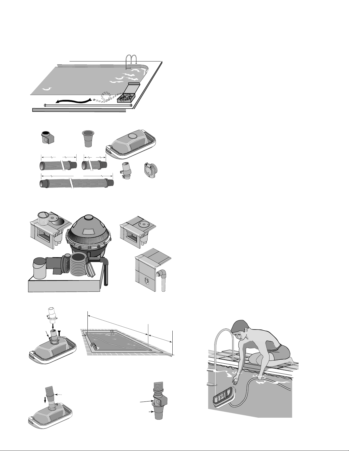
Movement around the pool
Random motion – The cleaner will visit most spots in
the pool in a 6 hour period. It is not specifically pro-
grammed and cannot see the dirt you are seeing. It is a
random motion cleaner.
The cleaner was designed to spend most of its time in
the deep end, where most of the floor and wall area
exists. During a 6 hour period the cleaner will visit the
shallow end a few times.
Rotating motion – The cleaner will rise up on one side
and pivot a few times per minute. This is normal and
provides the following:
1. Allows leaves that are being pushed or dragged along
to be sucked up into the vacuum chamber.
2. Allows the cleaner to:
Change direction
Get out of corners
Get away from ladders
Submerge below pool water level
Get off of domed main drain covers
Picks up big “stuff”
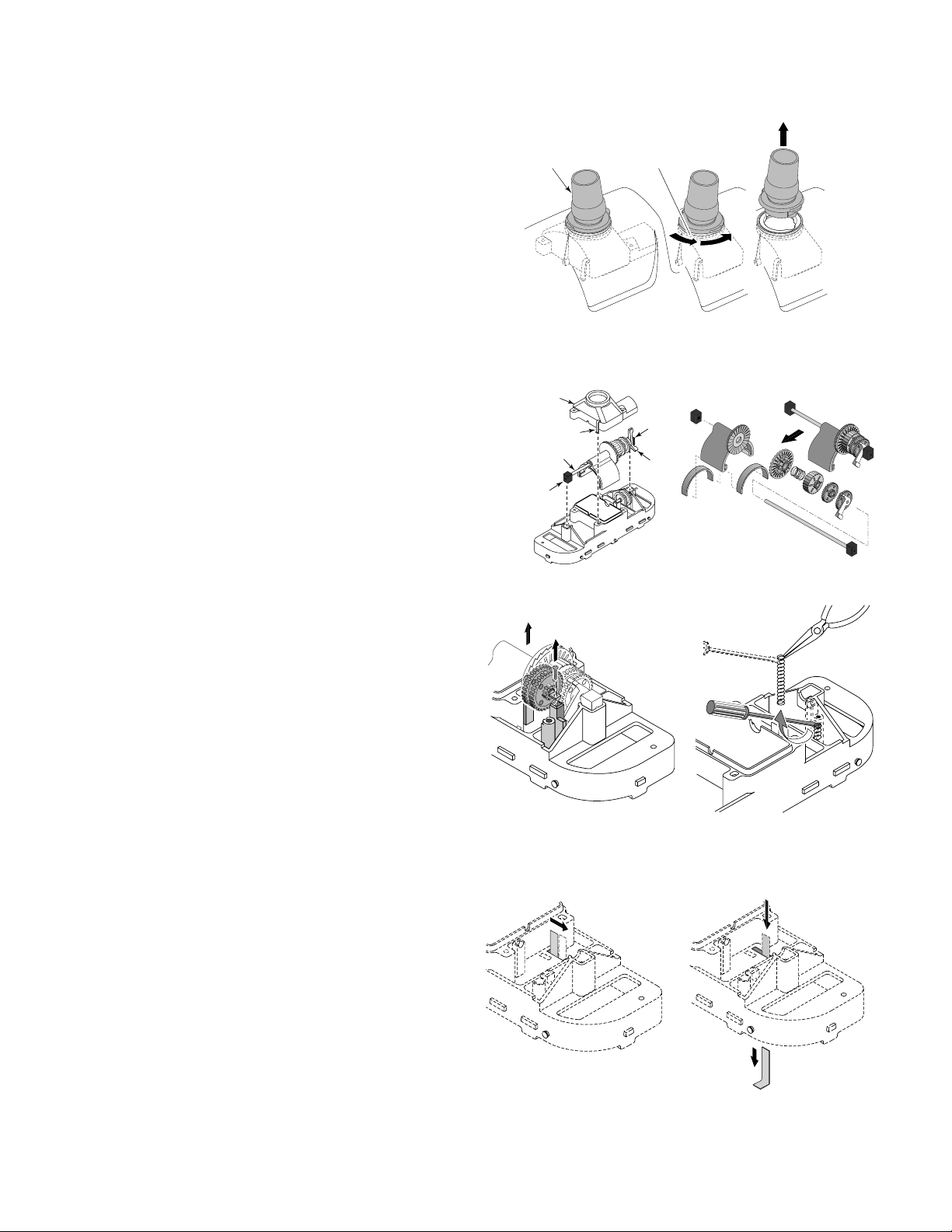
The cleaner will pick up some debris so large that it
may jam. Simply stop the pump and remove the debris
from the oscillator or the swivel assembly.
ABOUT THE CLEANER OPERATION:
ABOUT “FINE-TUNING” VACUUM ADJUSTMENTS AND CONNECTIONS:
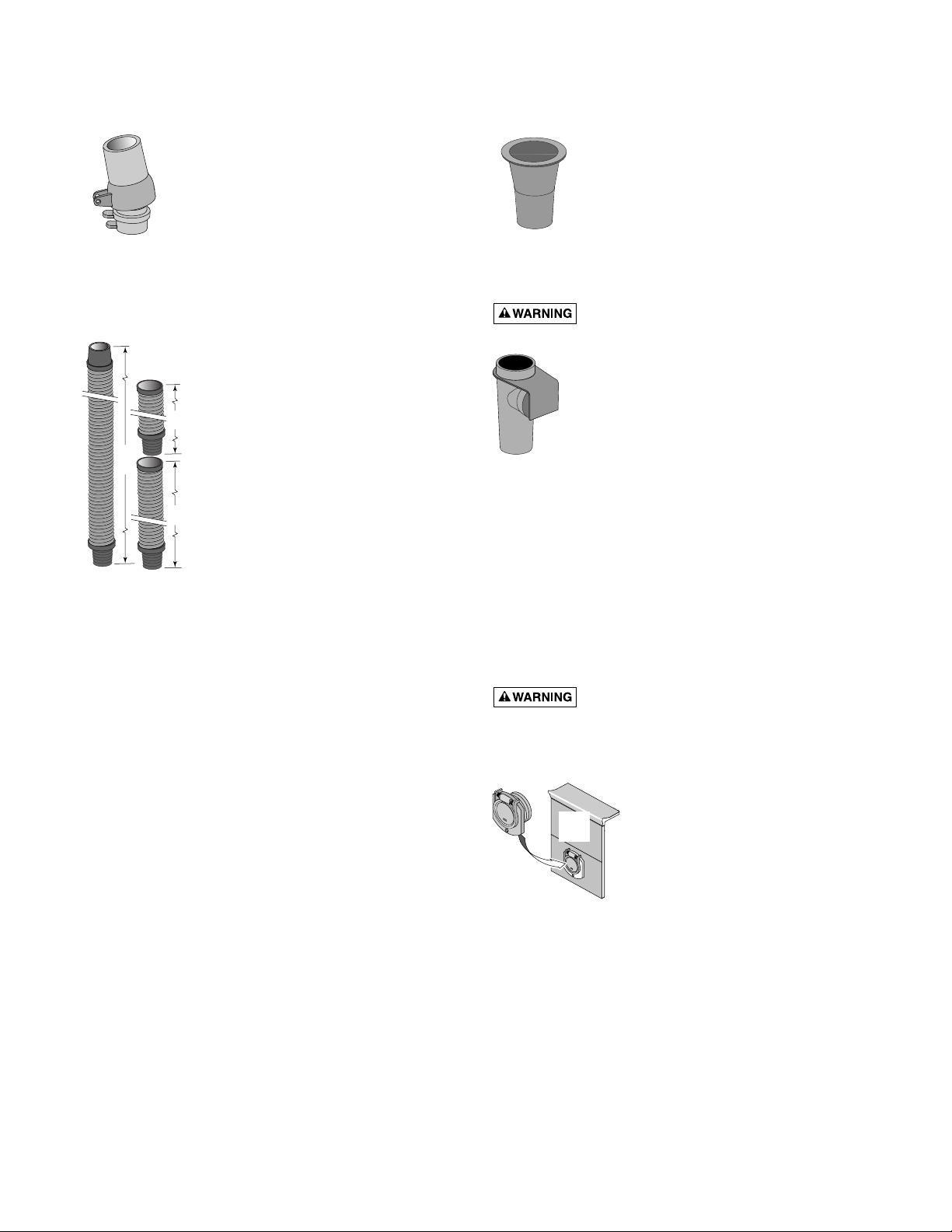
Pool pump suction is hazardous and
can cause entrapment with severe personal injury
or drowning. Use vacuum regulator (see instructions
below) in pool cleaner system at all times.
Note: Each pool’s hydraulic system and vacuum con-
nections are different. Be sure you have installed the
white plastic vacuum regulator before you “fine-tune”
the system. This not only regulates vacuum, but also
acts as a safety device.
Suction entrapment, injury, and drown-
ing hazard. If your pool has a dedicated suction
port (“vac port”) for vacuuming or for an automatic
pool cleaner, it must be covered when not in use. A
spring loaded safety cover (the “Vac Port Fitting”) is
included with this pool cleaner. Install it on the suction
port to prevent entrapment and injury. For details
please refer to the Vac Port instruction sheet included
with your Vac Port.
For the “NOVICE POOL OWNER” where vacuuming
is a new experience, please read all of the following
points, installation instructions, and trouble shooting
guide carefully.
Please note the following:
• “Vacuum” and “suction” are two words meaning the
same thing.
• “Dedicated suction line”, “vac port”, and
“vac fitting” are different terms for a
hole in the side wall of pool; this hole
is connected to the pump suction and
is dedicated to vacuuming.
•Some pools do not have a vac port. If
your pool does have one, please read
the “Suction Entrapment” warning at left.
For the “SEASONED POOL OWNER”: The automatic
pool cleaner connection and vacuum adjustments can
be similar to using your manual pool vacuum. Please
read on.
Valves (pump, skimmer, and main drain) and
vacuum adjustments
You may need to spend some time adjusting the skim-
mer and main drain valves in order to obtain the best
vacuum setting for good cleaner operation. Once you
have found the correct valve settings for best operation,
we suggest you mark the valves to ensure repeated
success.
At first, set valves to give maximum vacuum to the
skimmer or vac fitting you have elected to use.
Vac
Port

5
Too much vacuum?
You have too much vacuum if the cleaner climbs up the
pool wall past the water line to the point that the clean-
er sucks air and the pump loses prime. Frequent loss of
prime will damage the pump. To correct this, change
the black vacuum regulator cap marked “60” to the one
provided in your accessory bag marked “50”. If the
cleaner still climbs out and sucks air, open the main
drain valve slightly.
Not enough vacuum?
You don’t have enough vacuum if the cleaner moves
sluggishly or not at all. Be sure the filter system is clean
and all valves are adjusted to give you maximum vacu-
um. If the cleaner is still not moving, your pump may
not be strong enough to operate the cleaner. Also,
please refer to the Troubleshooting guide on Page 7.
In-Line leaf Canisters
If your pool is exposed to large quantities of leaves, we
suggest purchasing and installing an in-line leaf canis-
ter. A leaf canister will provide more debris-loading
capacity and also provides a water by-pass when the
canister is full. It is very important that the pump not
starve for water!
Dedicated suction line/vac port/vac fitting
Some pools have a dedicated wall fitting just for vacu-
uming. If the wall fitting connection is used, you may
notice that the clear pump lid shows signs of bubbles or
what appears to be the presence of air. To eliminate
this, slightly open the main drain valve to supplement
the water intake. The cleaner may slow down a bit
when you change the suction.
Skimmer connection
Some pool owners remove the skimmer basket and
connect the hose directly into the bottom of the skim-
mer. This method is OK for pools with minimal debris
and also for screened in pools.
For pools that have large quantities of “big stuff” to
pick up, we suggest using the bottom of the skimmer
connection in conjunction with an in-line leaf canister
(purchase the cannister locally). A leaf canister will pro-
vide more debris-loading capacity and also provides a
water by-pass when the canister is full. It is very impor-
tant that the pump not starve for water!
Skimmer vac plates
Some pool owners connect the hose to a skimmer vac
plate, which allows the skimmer basket to remain in
the skimmer. If this method is used, empty the basket
frequently. Also make sure that the vacuum regulator
provided is completely submerged so that it will not
suck air and damage the pump.
Skimmer vac plate vacuum
control adjusters
Some pool owners use one of a variety of manufacturer’s
skimmer vac plates. Some have a vacuum control ad-
juster, and some do not. The adjuster could be a screw-
type, a spring loaded apparatus, or a dial design. For
those vac plates with adjusters, it is important to adjust
them when fine tuning the vacuum for the cleaner.
ABOUT “FINE-TUNING” VACUUM ADJUSTMENTS AND CONNECTIONS:
If you have any questions, please call 1-800-752-0183

6
ABOUT THE CLEANER AND ACCESSORIES:
Swivel assembly (Figure 9)
Installing the swivel assembly is a snap.
Just insert it into the cleaner body and
give it a quarter turn.
If you attach a unidapt handle to the
swivel for manual vacuuming, be sure it
is the special, floating unidapt handle
provided with the cleaner (Replacement
Part No. AT5119). Use of a different
unidapt handle will hinder the cleaner’s performance.
Hoses (20’, 8’, and 4’ lengths – Figure 10)
The unit includes a 20’ hose, an 8’
hose, and a 4’ hose. Do not cut any of
these hoses.
The best hose length is at least 4’
longer than the distance from your
suction source (whether skimmer or
dedicated suction line) to the furthest
point in the pool. If the hose seems to
be too long, remove the 8’ section
provided. Do not cut the 20’ hose.
Be sure to connect the tapered end of
the 20’ hose (marked “connect to
cleaner”) to the cleaner head.
If additional hose is needed, use only
the specially designed 8’ extension hose from your
Aquatools dealer (order replacement part No. AT5111).
Use of another manufacturer’s hose will hinder cleaner
coverage (this also holds true for the 20’ hose). If you
need to replace the 20’ hose, buy only the original
equipment hose (order replacement part No. AT5821).
Hose (6” connector ) female x female (purchase acces-
sory No. AT5121) If required, this will accommodate a
male x male connection at the skimmer.
Reducer cone (Figure 11)
The reducer cone is required to make
most hose connections. When used, it
will keep the hose in place if the filter
system is stopped.
Automatic vacuum regulator (Figure 12A)
Hazardous suction. Can cause entrap-
ment with severe personal injury or drowning.
Vacuum regulator should be installed in
all situations. If the cleaner moves very
slowly or not at all (indicating low vacu-
um in the system), see Troubleshooting
Guide, Page 7.
The regulator includes two black rubber
regulator caps. One is installed on the
regulator at the factory, and one is in the
accessory bag. The cap marked “50” in the accessory
bag is for systems with extremely high vacuum. Use of
this cap will help prevent the cleaner from “walking”
out of the pool.
Make sure the vacuum regulator, especially the black
rubber cap, is submerged at all times. If not, the pump
will suck air through the regulator and lose prime. This
could damage the pump.
Vac port fitting (Figure 12B)
Suction entrapment, injury, and drown-
ing hazard. If your pool has a dedicated suction
port (“vac port”) for vacuuming or for an automatic
pool cleaner, it must be covered when not in use.
A spring loaded safety cover (the
“Vac Port Fitting”) is included
with this pool cleaner. Install it
on the suction port to prevent
entrapment and injury. For
details please refer to the Vac
Port instruction sheet included
with your Vac Port.
1883 0795
20'
8'
4'
Figure 9
Figure 10
Figure 11
Figure 12A
ABOUT BUMPER INSERTS
Bumper Inserts (see Key 2A, Page 10) help to make the
cleaner more buoyant to allow better access to the
shallow end of the pool. Do not install inserts from the
top; they will become jammed and not work properly.
Only install inserts from the bottom.
If the bumper on the cleaner appears to lift the cleaner
to the surface of the pool, check for trapped air in the
cleaner and hose. If no air is found, remove one
bumper insert block and watch and see if the cleaner
remains submerged and on the pool floor while work-
ing. If not, remove individual insert blocks as needed
until the cleaner rests on the pool floor and operates
properly.
Vac
Port
Figure 12B

7
SOLUTIONS:
1. Backwash and/or clean filter. Empty all baskets. This should help your cleaner attain the
desired oscillation rate of 400-600 times per minute.
2. Clear all debris from oscillator chamber, hose, or vac plate by-pass (if you have one).
3. Repair all sources of vacuum leaks (cracked vac plate, vac plate or reducer cone not seated
properly, cracked hose, vac plate by-pass adjusted too loosely).
4. Adjust valves to give maximum vacuum to the vacuum port or skimmer to which you are
attaching the cleaner hose. Reduce or shut off other skimmers and main (floor) drain.
Note: Each pool’s hydraulic system is different. It may require some adjustments to skimmer
and main valves before you achieve the vacuum setting required for the best cleaner to opera-
tion. Once determined, mark the valves at that position to ensure repeated success.
5. Filtration system (pump) does not develop enough vacuum. Consult your pool service
professional.
6. In hot water, the hose may kink. The hose, when old, may have developed leaks
(cracks or holes) or may get brittle. Purchase new hose.
NOTE: It must be an AquaTools hose for proper operation.
1. Oscillator is running too fast. Make sure vacuum regulator is installed.
2. If regulator is installed and cleaner still climbs out of the pool (sucking air), remove the black
rubber regulator cap and replace it with the cap marked #50 from the accessory bag.
3. If steps 1 and 2 do not solve the problem, slightly open the main drain valve until the cleaner
no longer climbs out of the pool.
1. A clean filter system will help the cleaner to move much faster. Also, be sure to clean all baskets.
2. Vinyl liner pools with a deep end hopper will require 6-8 hours to clean. In this time the
cleaner should make at least 4 trips to the shallow end. If not, call Customer Service at
1-800-752-0183.
3. Examine the turning brush mechanism as the cleaner is operating. To do this, you will have to
turn the cleaner over while it is running and submerged. If the turning brush does not move to
the “down” position within 2 minutes, call Customer Service at 1-800-752-0183.
4. The cleaner was not designed to work under solar covers. If you have a solar cover, only mini-
mal coverage can be expected.
5. At times strong winds may hinder cleaner coverage!
6. Any cleaner might miss a spot. Your cleaner has been designed to accommodate the attach-
ment of a vac-pole (telepole) by use of the handle in the accessory bag. Attach pole for spot
cleanups, steps, and swimouts.
1. Examine the turning brush mechanism as the cleaner is operating. To do this, you will have to
turn the cleaner over while it is running and submerged. If the turning brush does not move to
the “down” position within 2 minutes or less, call Customer Service at 1-800-752-0183.
1. This cleaner was not designed to clean these areas. Use the handy telepole attachment, connect
the pole, and clean missed areas.
1. This is normal with some filter systems that develop a surge of back pressure when the system
shuts off. The cleaner will right itself when the system is restarted.
1. Use reducer cone when connecting to the skimmer or vac port.
1. Hose might be too short. Desired length can be measured from the point where the hose is con-
nected, to the furthest point of the pool, plus a minimum of an additional 4’. If needed, pur-
chase an extension hose from your local dealer. Do not cut extension hose – use it full length
even if it is a little long.
1. For best results, when hose is not in use, store it uncoiled, flat, and straight. If coiling is
necessary, coil loosely.
2. Lay hose out flat and straight in the sunlight for a few hours prior to use.
ABOUT TROUBLESHOOTING
SITUATION
Cleaner does not move.
Oscillator is very slow.
Cleaner climbs past water
line of pool causing pump
to lose prime (suck air).
Cleaner coverage not as
expected.
Cleaner “stuck” in one
spot (more than 15
minutes).
Steps and “swimouts” are
not clean.
Cleaner flips on its back
when pump stops.
Hose comes loose when
pump stops.
Cleaner hovers in one
area with hose fully
extended.
Hose keeps coiling up.
If you have any questions, please call 1-800-752-0183

8
If you have any questions, please call 1-800-752-0183
1. Remove swivel assembly (Figure 13) from the top of
the cleaner by turning it 1/4-turn counterclockwise
and pulling straight up on it.
2. Turn cleaner upside down. Remove 4 screws and
remove lower body assembly from shroud.
3 . Turn lower body assembly right side up. Unsnap the
2 clips on the oscillator chamber cap (Figure 14A); lift
it off.
4. Pull the long gear shaft straight up (Figure 14A) by
the blocks on the ends of the shaft. Hold the seals in
the oscillator and the blocks on the shaft. The cam
may interfere with the shaft mounting post; if so, turn
it slightly on the shaft until it clears the post. The shaft
assembly can now be disassembled (Figure 14B).
5. Slide the long gear shaft out of the oscillator (with
gears, complete); make sure that you don’t lose the
seals out of the oscillator which may fall out at this
point (Figure 14B).
5A. Oscillator seals are replaceable.
5B. Ratchet gear set and long shaft are replaceable as a
unit.
6. Remove the set screw, short gear shaft, and gears
(Figure 15); do not lose the gears off of the shaft.
7. With a small screwdriver (such as a jeweler’s screw-
driver), a pencil, or a pen point, depress and remove
the coil spring from the movable brush mounting
post (Figure 16). Replace the brush and the spring if
necessary.
8. The metal ratchet tab slides out of its slot sideways;
replace it by removing the center brushes and sliding
in a new ratchet tab until it is flush with the edge of
plastic holder (Figures 17 and 18). Replace the center
brushes.
9. The brush ring pops out of the cleaner body for easy
replacement.
10. If you need to replace the bumper, turn the shroud
and bumper assembly upside down and remove the
two screws holding the bumper to the shroud.
1889 0795
Clip
Ocillator
Chamber
Cap
Block
Long Gear Shaft
Block
Cam
Locked Twist CCW
1/4 Turn
Pull Straight
Up
"Click" at
this point
Swivel
assembly
3337 1098
4374 0503
1887 0795
1886 0795
1. Slide metal ratchet tab
toward end of cleaner body
1885 0795
2. Slide metal ratchet tab
down through cleaner body
1884 0795
Figure 14A Figure 14B
Figure 13
Figure 15 Figure 16
Figure 17 Figure 18
ABOUT DISASSEMBLY

9
ABOUT ASSEMBLY
If you have any questions, please call 1-800-752-0183
1. Put both white seals in the oscillator; hold them in
place.
2. Install the oscillator on the long gear shaft. Install the
ratchet gear on the shaft so that the teeth engage the
ratchet on the oscillator. Install the spring, ratchet
drum, pinion gear (large gear first), and cam (gear end
first) on the shaft (See Figure 19). Hold the gears on the
shaft while installing them, and compress the clutch
spring to allow assembly to slip into place between the
posts (See Figure 19).
3. Install the long gear shaft and end blocks in the clean-
ing head with the large arm of the cam down (see
Figure 20).
4. Reinstall the short gear shaft, set screw, and two gears
(See Figure 21); the small pinion gears and the shaft set
screw go on the side toward the end of the cleaner –
away from the oscillator box. Make sure that the gears
engage the gears on the long gear shaft.
5. Install the oscillator chamber cap and clip it in place.
6. Install the rubber vacuum skirt on the cleaner with the
word ‘OUTSIDE’ showing. Start at the large pin on the
back of the cleaner head (See Figure 22) and work
around the cleaner. Make sure the skirt is flush against
the stop strips on the cleaner head (see Figure 23).
7. Turn the cleaner over. If you removed the bumper and
brush ring, replace them now.
8. Install the lower body assembly in the shroud. Fasten
the cleaning head in place with 4 screws (2 long, 2 short
– see Figure 24).
NOTE: Make sure that you do not dislodge the rubber
vac skirt while inserting the lower body assembly past
the brush ring.
1894 0795
Figure 19
Swing Cam
Arm up for
Clearance
Make sure Oscillator
is partially inserted in
chamber while reinstalling
Shaft Assembly
Oscillator
Chamber
Figure 20
Figure 21
Start here with
large button when
installing vacuum skirt.
OUTSIDE
'Outside' will show
(facing out) when
skirt is correctly installed. Rubber
vacuum skirt
1893 0795
Figure 22
This
Not
This
Figure 23
#10-16x1" Screws
#10-16x1-3/4" Screws
Center
Brush
Location
Center
Brush
Location
Bottom View of Cleaner
1891 0795
Figure 24

Repair Parts
Key Part Part
No. Description No.
1Swivel Assembly AT5112
2Bumper AT5802
2A Bumper Insert Kit (Set of 4) AT5820
3Screw Kit (4 short, 2 long) AT5804
4Shroud AT5801
5Brush Ring AT5805
6Oscillator Chamber Cap AT5806
7Cam Kit (2 & 3 Leg Cams) AT5807
8Idler Gear Kit (Incl. 3 Gears) AT5809
9Block Kit (Incl. 2 Blocks) AT5812
10 Long Gear Shaft (Stainless Steel) AT5813
11 Set Screw #4 Self Tapping##
11A Shaft Kit, Stainless Steel (includes Set Screw) GW9536
12 Lower Body* GW9535
13 Lift Brush AT5817
14 Vacuum Skirt AT5808
15 Lift Brush Spring AT5822
16 Ratchet Tab (Stainless Steel) AT5823
17 Oscillator Seal Kit (Incl. 2 Seals) AT5109
18 Oscillator Assembly Kit (Incl. Key # 17) AT5803
(Ratchet Assembly not sold separately)
19 Center Brush Kit (Set of 2) AT5113
•4’ Vacuum Hose Extension (1/pkg.) AT5819
•20’ Vacuum Hose (1/pkg.) AT5821
•8’ Vacuum Hose Extension (1/pkg.) AT5111
•Replacement Hose Kit
(1 each 20’, 8’ and 4’ Hose) AT5816
•Vacuum Regulator Assembly AT5116
•Vacuum Regulator Cap Kit
(Includes #50, #60, #70 Caps) AT5118
•Reducer Cone AT5115
•Unidapt Handle AT5119
•6” Female to Female Adapter Hose** AT5121
•Vac Port Fitting GW9530
•Not illustrated.
*Includes Key Nos. 6, 11A, 13, 15, 16, two idler gears
and 2-arm cam.
** Accessory – purchase separately.
## Not available separately.
Optional Accessories
Unidapt
Handle
No. GW9019
Vacpole
R
1897 0795
If you have any questions, please call 1-800-752-0183
1
2
2A
3
3
4
5
6
7
8
8
9
3
3
3
10
11
12
11A
13
14
15
9
19
18
17
16
1896 0795
10
Unidapt
Handle,
No. AT5119
Vacpole

11
ABOUT MAINTENANCE AND CARE
Hazardous suction. Stop pump before
attempting to clean pool cleaner.
•Keep skimmer basket and pump strainer basket clean
and free of debris.
•If cleaner jams with large debris (leaves, sticks, etc.),
try cleaning debris first from bottom of unit. If this
doesn’t clear unit, remove top swivel assembly (turn
1/4 turn) and clear the debris from the top.
•Remove the pool cleaner from the pool before super
chlorinating (shocking) or chemical balancing. Wait at
least four hours after the chemical procedure before
reinstalling the cleaner.
•Make sure that the cleaner’s brush bristles don’t
become deformed during storage. Store the unit so
that it doesn’t sit on the bristles and so that nothing
compresses them.
•If possible, do not coil the hose. Remove the hose from
the cleaner when removing the cleaner from the pool.
Store the hose flat and straight.
•Periodically examine bristles and vacuum skirt for
wear or distortion. Replace if necessary. See
"Assembly", Page 9.
•If necessary to remove oscillator, see "Disassembly",
Page 8.
•Don’t store the cleaner with the hose connected to the
cleaner body or with the hose coiled. To do so will
cause the hose to take a set or kink over a period of
time. When reinstalled in the pool, the hose will tend
to stay coiled and will cause the cleaner to malfunc-
tion.
•If the hose has taken a set, uncoil it as far as possible
without damaging it and lay it out in the sun for sev-
eral hours to straighten itself. Once it has relaxed and
straightened out, store it laid out flat and straight (no
coiling) if possible. If no storage area is available that
will allow this, coil the hose as loosely as possible and
expect to have to let it straighten for a while before
using the cleaner again.
•Make sure the lift brush is retracted during storage or
else that the cleaner is supported such that the lift
brush is not taking any of the cleaner’s weight. If the
lift brush is down during storage and the cleaner rests
on it, the brush bristles will collapse over time and the
cleaner will no longer turn during operation as it was
designed to do.
HOSE STORAGE
OK, Not Recommended: Hose is
disconnected from cleaner and
loosely coiled (no sharp bends).
Wrong: Storing cleaner with hose
connected will damage hose and
void the hose warranty.
Best: Hose stored correctly – laid
out straight, not connected to
cleaner.

▲Retain Warranty Certificate (upper portion) in a safe and convenient location for your records.
DETACH HERE: Fill out bottom portion completely and mail within 10 days of purchase/installation to:
▼ AquaTools, Attn: Warranty Dept., 293 Wright St., Delavan, WI 53115
Pumps, filters, skimmers, underwater lights (except bulbs),
accessories and fittings manufactured by AquaTools are
warranted to be free of defects in material and workman-
ship for one (1) year from date of installation.
Product specific warranties: Year from date
of installation
Module Filters – Tanks . . . . . . . . . . . . . . . . . . . . 10 years
Internal filter components and valves . . . . 1 year
Automatic Pool Cleaners including Hose . . . . . . 2 years
Sand Filters – Tanks . . . . . . . . . . . . . . 10 years pro-rated*
Valve and Internal components.. . . . . . . . . . 1 year
Above-ground Cartridge –
Filter Tank. . . . . . 5 years pro-rated (1st 2 years full)
Elements . . . . . . . . . . . . . . . . . . . . . . . . . . . 1 year
Sand Systems – Tanks . . . . . . . . . . . . . 10 years pro-rated*
Pumps . . . . . . . . . . . . . . . . . . . . . . . . . . . . . 1 year
Valve and Internals . . . . . . . . . . . . . . . . . . . 1 year
Cartridge Systems – Filter Tank . . . . . . . . . . . . . . . 1 year
Pumps . . . . . . . . . . . . . . . . . . . . . . . . . . . . . 1 year
Module Filter Systems – Tanks . . . . . . . . . . . . . . 10 years
Pumps . . . . . . . . . . . . . . . . . . . . . . . . . . . . . 1 year
Platform and Internals . . . . . . . . . . . . . . . . . 1 year
Pumps . . . . . . . . . . . . . . . . . . . . . . . . . . . . . . . . . . 1 year
When equipped with A.O. Smith
2-compartment motors (Does not include
pumps sold as part of a systems package). . 2 years
The foregoing warranties relate to the original consumer
purchaser (“Purchaser”) only. AquaTools shall have the
option to repair or replace the defective product, at its sole
discretion. Purchasers must pay all labor and shipping
charges necessary to replace the product covered by this
warranty. Requests for warranty service must be made
through the installing dealer. This warranty shall not apply
to any product that has been subject to negligence, misap-
plication, improper installation or maintenance, or other
circumstances which are not in AquaTools’ direct control.
* Full warranty coverage is in effect for one year after instal-
lation. The pro-rated warranty covers the tank only during
the 2nd through 10th year after installation. The amount
covered decreases by 10% each year. (ie., 2nd year 90%
covered, 3rd year 80% covered, etc.).
This warranty sets forth AquaTools’ sole obligation and
Purchaser’s exclusive remedy for defective products.
AquaTools SHALL NOT BE LIABLE FOR ANY CONSEQUEN-
TIAL, INCIDENTAL OR CONTINGENT DAMAGES WHAT-
SOEVER.
THE FOREGOING WARRANTIES ARE EXCLUSIVE AND IN
LIEU OF ALL OTHER EXPRESS WARRANTIES. IMPLIED
WARRANTIES, INCLUDING BUT NOT LIMITED TO THE
IMPLIED WARRANTIES OF MERCHANTABILITY AND FIT-
NESS FOR A PARTICULAR PURPOSE, SHALL NOT EXTEND
BEYOND THE DURATION OF THE APPLICABLE EXPRESS
WARRANTIES PROVIDED HEREIN.
Some states do not allow the exclusion or limitation of inci-
dental or consequential damages or limitations on how
long an implied warranty lasts, so the above limitations or
exclusion may not apply to you. This warranty gives you
specific legal rights and you may also have other rights
which vary from state to state.
Supersedes all previous publications.
AquaTools
293 Wright Street
Delavan, WI 53115
Warranty Registration Card
Name
Address
City State Zip
Purchase Date
Product Purchased
■■New installation ■■Replacement
Type of Pool ■■Inground ■■Vinyl ■■Fiberglass ■■Gunite
Size of Pool
Years pool has been in service ■■less than 1 ■■1-3 ■■3-5 ■■5-10
Purchased from:
Company name
Address
City State Zip
Please send me more information on these
other products from AquaTools.
■■Pumps ■■Filters ■■Automatic Pool Cleaners
■■Maintenance Equipment ■■Test Strips
S4877AT (Rev. 5/15/00)
AquaTools®LIMITED WARRANTY
Other manuals for AT5800
1
Table of contents
Other AquaTools Swimming Pool Vacuum manuals
Popular Swimming Pool Vacuum manuals by other brands

Zodiac
Zodiac CyclonX OC 3300 TILE Installation and user manual

Zodiac
Zodiac BARACUDA RANGER Quick start guides

Fiap
Fiap SurfSkim Active operating manual

Zodiac
Zodiac CYBERNAUT NT quick start guide

Pentair Pool Products
Pentair Pool Products LEGEND installation guide

Zodiac
Zodiac ALPHA iQ quick start guide

baracuda
baracuda alpha 3 Owner's manual and quick installation instructions

WaterTech
WaterTech Pool Blaster PRO 900 user manual

Aqua Products
Aqua Products Above GroundSwimming Pool CleanersResidential... owner's manual

Chasing
Chasing CM600 user manual

Maytronics
Maytronics Dolphin Mass 13 User instructions

AREBOS
AREBOS AR-HE-PRAPP manual