AquaTools AT5800 User manual

AUTOMATIC POOL CLEANER
O W N E R’ S M A N U A L
OPERATION, TROUBLESHOOTING & PARTS
AquaTools
293 Wright Street, Delavan, WI 53115
International: 262-728-5551, FAX: 262-728-7550
© 2005, AquaTools AT787 (4/13/05)
ABOUT SAFETY
• Before installing the cleaner, review and
understand all warnings and safety information
on inside cover of manual.
ABOUT INSTALLATION
• Please use the convenient, water resistant
Installation Instructions card.
INDEX
About Safety .............................................................2
About Your Pool and Filter System ...........................2
About Installation .................................................3, 4
About the Cleaner Operation....................................5
About ”Fine Tuning” Vacuum Adjustments...........5, 6
About the Cleaner and Accessories...........................7
About Troubleshooting .............................................8
About Disassembly ...................................................9
About Assembly......................................................10
Repair Parts.............................................................11
About Maintenance ................................................12
Warranty.................................................................13
1873 0795
Model AT5800

2
Before installing your cleaner, review and
understand all warnings and safety informa-
tion on the inside front cover of this manual.
Pre-installation check list
Before installing the cleaner in a vinyl liner pool:
Check liner closely for signs of deterioration or damage
from age, chemicals, pool wall damage, etc. If any damage
is found, have a qualified pool professional make all neces-
sary repairs. Also, if there are stones, roots, etc., under the
liner, remove them before installing the cleaner.
Before installing the cleaner in a gunite pool or a pool
that is partially or completely tiled:
Repair loose tiles and tighten any loose light rings.
Before installing the cleaner, clean your filter system:
Make sure you have cleaned the filter, including back-
washing, rinsing, and emptying all baskets. A clean system
is necessary for proper cleaner operation and coverage.
Before installing the cleaner, fill the hose with water:
Always make sure the cleaner head is submerged and
the hose is full of water before connecting the hose to
the filtration system (whether through a skimmer or dedi-
cated wall fitting). Air in the system can damage the
pump through dry running and overheating.
Before installing the cleaner, understand cleaner coverage:
The cleaner is designed to rid your pool of debris in
approximately 4-6 hours. Less time could be needed,
depending on the pool size.
The cleaner was not designed to automatically clean
steps or swimouts or to work under a solar cover. It was
also not designed to do initial cleanup for a new pool or
when opening your pool for the season.
Suction entrapment, injury, and drown-
ing hazard. If your pool has a dedicated suction
port (“vac port”) for vacuuming or for an automatic
pool cleaner, it must be covered when not in use.
A spring loaded safety cover is included with your
cleaner. Install it on the suction port to prevent
entrapment and injury.
ABOUT YOUR POOL AND FILTER SYSTEM:
This is the safety alert symbol. When you see this
symbol on your system or in this manual, look for
one of the following signal words and be alert to the
potential for personal injury.
warns about hazards that will cause
death, serious personal injury, or major property dam-
age if ignored.
warns about hazards that can cause
death, serious personal injury, or major property dam-
age if ignored.
warns about hazards that will or can
cause minor personal injury or property damage if
ignored.
Carefully read and follow all safety instructions in this
manual and on equipment. Keep safety labels in good
condition; replace if missing or damaged.
Hazardous suction.
Can trap and tear
hair or body parts.
Can cause drowning.
Do not play with cleaner
or hose or apply to body.
Do not let children use or
play with pool cleaner.
Stop pump before
attempting to clean unit.
1058 0594
Oscillator may
injure hands or fingers.
Stop pump before attempt-
ing to clean out pool cleaner
head.
Hose can trip
or entangle swimmers.
Do not allow swimmers in
pool while pool cleaner is
operating.
Please read the following before installing
your new automatic pool cleaner!
ABOUT SAFETY:

Step 1: Install vacuum port door fitting
If there is no spring-loaded door on the vacuum port,
install the included cover.
If you pool only has a skimmer, and no dedicated vacu-
um port, proceed to Step 2.
1. Screw the fitting into the port opening.
2. Orient the fitting so the arrow on the door points up.
3. Secure the cover by tightening the allen-screw below the
door.
Step 2: Straighten hose (Figure 2)
Remove and uncoil the hose from the carton. Lay it out
in the sunlight, flat and straight.
Step 3: Check parts (Figure 3)
Cleaner, black plastic swivel assembly, white rubber
reducer cone, one 20’, one 8’, and one 4’ hose, white
plastic vacuum regulator, regulator cap, vac port fitting
and flow gauge.
Step 4: Clean filter system (Figure 4)
Backwash and clean filter; rinse; clean all baskets, etc.
Start pump.
Step 5: Adjust valves for vacuuming (Figure 5)
Decide on the vacuum connection you are going to use
(either a skimmer or a dedicated wall fitting) and adjust
the pump valves (if your system has valves) to direct all
vacuum there.
Close the main drain (also see “About Fine Tuning the
Vacuum”, Page 5).
Step 6: Assemble cleaner (Figure 6)
Insert swivel assembly into cleaner; twist 1/4 turn.
3
ABOUT INSTALLATION
Please use the convenient, water resistant,
“Installation Instructions”
card.
Regulator Regulator
Cap
Swivel
Ass'y Reducer
Cone
Vacuum
Port
Flow
Gauge
Hose
Handle
Cleaner
1902 0795
8'
20'
4'
M
A
X
I
M
U
M
F
L
O
W
M
I
N
I
M
U
M
F
L
O
W
1880 0795
Skimmer
Vac
Port
Swivel
Assembly
1876 0795
Figure 3
Figure 4
Figure 1
1882 0795
Figure 2
Figure 5
Figure 6

4
Step 7: Measure hose length needed (Figure 7)
Before connecting the hose, lay it out from the vacuum
connection you are using (whether skimmer or dedicated
wall fitting) to the furthest point of the pool. The hose
should be at least 4’ longer than this. More than 4’
longer is OK.
Do not cut the hose.
Fill the hose with
water and keep the ends accessible.
Step 8: Install Regulator
Install the regulator and reducer cone in the skimmer.
Refer to illustrations A and B on the following page.
Attach the end of the hose to the regulator (Figure 8), or
to the vacuum port (Figure 9) depending upon your pool.
Step 9: Check Flow
Close the main drain and insert one end of the hose into
the vacuum source (skimmer or vacuum port: see
below). Insert the flow gauge into the other end of the
hose. Keep the hose and flow gauge underwater. Turn on
the pump.
With the pump running, adjust the regulator until the
indicator on the flow gauge is between minimum and
maximum flow.
Remove the flow gauge and attach the hose to the cleaner.
INSTALLATION
Disc Indicator
Figure 10
Hose must equal longest stretch — — plus at least 4 feet.
Figure 7
Skimmer
Regulator
To Pump
Adapter Cone
Figure 8: Regulator
installed with hose
connection
Skimmer
Regulator
Cap
To Pump
Adapter Cone
Figure 9: Regulator
installed with cap

Step 10: Connect Hose to Cleaner.
Connect the hose cuff of the 20’ hose to the swivel
assembly in cleaner (correct end of hose is marked).
Fill the cleaner with water and let it sink to the bottom.
Verify hose connections as shown below, and that gate
valves are fully open in the suction line.
5
INSTALLATION
Hose Cuff
marked
"Connect
to Cleaner"
1875 0795
Figure 11
Figure 12
Reducer
Cone
Vacuum
Regulator
Water
Level
Skimmer
Port
Gate valve for
skimmer must
be fully open
Water
Level
Reducer
Cone
Vacuum
Regulator
with Cap
Skimmer
Gate valve for
vacuum port must
be fully open
B
A
HOSE CONNECTIONS:
Follow drawing that most closely resembles your skimmer installation.

6
Clicking sound
This sound is the oscillator moving back and forth in the
oscillator chamber. The best speed for it is about 500
oscillations per minute. The vibration created by the
oscillator moves the bristles and the cleaner. If the oscil-
lator is running too fast, the cleaner will have a tendency
to climb up the pool wall past the waterline, or “walk
out of the pool”.
Movement around the pool
Random motion – The cleaner will visit most spots in the
pool in a 6 hour period. It is not specifically programmed
and cannot see the dirt you are seeing. It is a random
motion cleaner.
The cleaner was designed to spend most of its time in
the deep end, where most of the floor and wall area
exists. During a 6 hour period the cleaner will visit the
shallow end a few times.
Rotating motion – The cleaner will rise up on one side
and pivot a few times per minute. This is normal and
provides the following:
1. Allows leaves that are being pushed or dragged along to
be sucked up into the vacuum chamber.
2. Allows the cleaner to:
Change direction
Get out of corners
Get away from ladders
Submerge below pool water level
Get off of domed main drain covers
Picks up big “stuff”
The cleaner will pick up some debris so large that it may
jam. Simply stop the pump and remove the debris from
the oscillator or the swivel assembly.
ABOUT THE CLEANER OPERATION:
ABOUT “FINE-TUNING” VACUUM ADJUSTMENTS AND CONNECTIONS:
Pool pump suction is hazardous and
can cause entrapment with severe personal injury
or drowning. Use vacuum regulator (see instructions
below) in pool cleaner system at all times.
Note: Each pool’s hydraulic system and vacuum connec-
tions are different. Be sure you have installed the white
plastic vacuum regulator before you “fine-tune” the sys-
tem. This not only regulates vacuum, but also acts as a
safety device.
Suction entrapment, injury, and drown-
ing hazard. If your pool has a dedicated suction
port (“vac port”) for vacuuming or for an automatic
pool cleaner, it must be covered when not in use. A
spring loaded safety cover (the “Vac Port Fitting”) is
included with this pool cleaner. Install it on the suction
port to prevent entrapment and injury. For details
please refer to the Vac Port instruction sheet included
with your Vac Port.
For the
“NOVICE POOL OWNER”
where vacuuming is a
new experience, please read all of the following points,
installation instructions, and trouble shooting guide carefully.
Please note the following:
• “
Vacuum
” and “
suction
” are two words meaning the
same thing.
• “
Dedicated suction line
”, “
vac port
”, and
“
vac fitting
” are different terms for a
hole in the side wall of pool; this hole is
connected to the pump suction and is
dedicated to vacuuming.
• Some pools do not have a vac port. If
your pool does have one, please read
the “Suction Entrapment” warning at left.
For the
“SEASONED POOL OWNER”
: The automatic
pool cleaner connection and vacuum adjustments can be
similar to using your manual pool vacuum. Please read
on.
Valves (pump, skimmer, and main drain) and
vacuum adjustments
You may need to spend some time adjusting the skimmer
and main drain valves in order to obtain the best vacuum
setting for good cleaner operation. Once you have found
the correct valve settings for best operation, we suggest
you mark the valves to ensure repeated success.
At first, set valves to give maximum vacuum to the skim-
mer or vac fitting you have elected to use.
Vac
Port

7
Too much vacuum?
You have too much vacuum if the cleaner climbs up the
pool wall past the water line to the point that the cleaner
sucks air and the pump loses prime. Frequent loss of
prime will damage the pump. To correct this, adjust the
regulator by turning the knob counter-clockwise. This
will decrease the suction. If the cleaner still climbs out
and sucks air, open the main drain valve slightly.
Not enough vacuum?
You don’t have enough vacuum if the cleaner moves slug-
gishly or not at all. Be sure the filter system is clean and the
regulator and all valves are adjusted to give you maximum
vacuum. If the cleaner is still not moving, your pump may
not be strong enough to operate the cleaner. Also, please
refer to the Troubleshooting guide on Page 8.
In-Line leaf Canisters
If your pool is exposed to large quantities of leaves, we
suggest purchasing and installing an in-line leaf canister.
A leaf canister will provide more debris-loading capacity
and also provides a water by-pass when the canister is
full. It is very important that the pump not starve for
water!
Dedicated suction line/vac port/vac fitting
Some pools have a dedicated wall fitting just for vacu-
uming. If the wall fitting connection is used, you may
notice that the clear pump lid shows signs of bubbles or
what appears to be the presence of air. To eliminate this,
slightly open the main drain valve to supplement the
water intake. The cleaner may slow down a bit when
you change the suction.
Skimmer connection
Some pool owners remove the skimmer basket and con-
nect the hose directly into the bottom of the skimmer.
This method is OK for pools with minimal debris
and also for screened in pools.
For pools that have large quantities of “big stuff” to pick
up, we suggest using the bottom of the skimmer connec-
tion in conjunction with an in-line leaf canister (purchase
the cannister locally). A leaf canister will provide more
debris-loading capacity and also provides a water by-
pass when the canister is full.
It is very important that the
pump not starve for water!
Skimmer vac plates
Some pool owners connect the hose to a skimmer vac
plate, which allows the skimmer basket to remain in the
skimmer. If this method is used, empty the basket fre-
quently. Also make sure that the vacuum regulator pro-
vided is completely submerged so that it will not suck air
and damage the pump.
Skimmer vac plate vacuum
control adjusters
Some pool owners use one of a variety of manufacturer’s
skimmer vac plates. Some have a vacuum control adjuster,
and some do not. The adjuster could be a screw-type, a
spring loaded apparatus, or a dial design. For those vac
plates with adjusters, it is important to adjust them when
fine tuning the vacuum for the cleaner.
ABOUT “FINE-TUNING” VACUUM ADJUSTMENTS AND CONNECTIONS:
If you have any questions, please call 1-800-752-0183

8
ABOUT THE CLEANER AND ACCESSORIES:
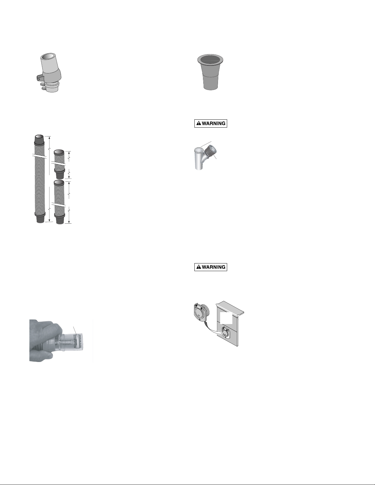
Swivel assembly (Figure 13)
Installing the swivel assembly is a snap.
Just insert it into the cleaner body and
give it a quarter turn.
If you attach a unidapt handle to the
swivel for manual vacuuming, be sure it
is the special, floating unidapt handle
provided with the cleaner (Replacement
Part No. AT5119). Use of a different
unidapt handle will hinder the cleaner’s performance.
Hoses (20’, 8’, and 4’ lengths – Figure 14)
The unit includes a 20’ hose, an 8’
hose, and a 4’ hose. Do not cut any of
these hoses.
The best hose length is at least 4’
longer than the distance from your
suction source (whether skimmer or
dedicated suction line) to the furthest
point in the pool. If the hose seems to
be too long, remove the 8’ section pro-
vided. Do not cut the 20’ hose.
Be sure to connect the tapered end of
the 20’ hose (marked “connect to
cleaner”) to the cleaner head.
If additional hose is needed, use only
the specially designed 8’ extension hose
from your Aquatools dealer (order replacement part No.
AT5111). Use of another manufacturer’s hose will hinder
cleaner coverage (this also holds true for the 20’ hose). If
you need to replace the 20’ hose, buy only the original
equipment hose (order replacement part No. AT5821).
Hose (6” connector ) female x female (purchase accesso-
ry No. AT5121) If required, this will accommodate a
male x male connection at the skimmer.
Flow gauge (Figure 15A)
The flow gauge is inserted into
the hose before attaching the
hose to the cleaner. With the
pump running, the regulator is
adjusted until the indicator on
the flow gauge is between
maximum and minimum flow.
Reducer cone (Figure 15B)
The reducer cone is required to make
most hose connections. When used, it will
keep the hose in place if the filter system
is stopped.
Automatic vacuum regulator (Figure 16A)
Hazardous suction. Can cause entrap-
ment with severe personal injury or drowning.
Vacuum regulator should be installed in
all situations. The vacuum regulator has
an adjustment knob. If suction is too high,
the knob is turned counter-clockwise to
decrease the suction. If the suction is too
low, then the knob is turned clock-wise to
increase the suction.
The regulator is installed in the skimmer.
The hose will connect to the dedicated vacuum port, or
to the top of the regulator if the pool lacks a suction port.
The regulator must be capped if a hose is not connected
to it.
Make sure the vacuum regulator is submerged at all
times. If not, the pump will suck air through the regulator
and lose prime.
This could damage the pump.
Vac port fitting (Figure 16B)
Suction entrapment, injury, and drown-
ing hazard. If your pool has a dedicated suction
port (“vac port”) for vacuuming or for an automatic
pool cleaner, it must be covered when not in use.
A spring loaded safety cover (the
“Vac Port Fitting”) is included with
this pool cleaner. Install it on the
suction port to prevent entrapment
and injury. For details please refer
to the Vac Port instruction sheet
included with your Vac Port.
1883 0795
20'
8'
4'
Figure 13
Figure 14
Figure 15B
Disc Indicator
Figure 15A
Cap
Adjustment
Knob
Figure 16A
ABOUT BUMPER INSERTS
Bumper Inserts (see Key 2A, Page 10) help to make the
cleaner more buoyant to allow better access to the shal-
low end of the pool. Do not install inserts from the top;
they will become jammed and not work properly. Only
install inserts from the bottom.
If the bumper on the cleaner appears to lift the cleaner
to the surface of the pool, check for trapped air in the
cleaner and hose. If no air is found, remove one
bumper insert block and watch and see if the cleaner
remains submerged and on the pool floor while work-
ing. If not, remove individual insert blocks as needed
until the cleaner rests on the pool floor and operates
properly.
Vac
Port
Figure 16B

9
SOLUTIONS:
1. Backwash and/or clean filter. Empty all baskets. This should help your cleaner attain the desired
oscillation rate of 400-600 times per minute.
2. Clear all debris from oscillator chamber, hose, or vac plate by-pass (if you have one).
3. Repair all sources of vacuum leaks (cracked vac plate, vac plate or reducer cone not seated prop-
erly, cracked hose, vac regulator adjusted too loosely).
4. Adjust valves to give maximum vacuum to the vacuum port or skimmer to which you are attach-
ing the cleaner hose. Reduce or shut off other skimmers and main (floor) drain.
Note: Each pool’s hydraulic system is different. It may require some adjustments to skimmer and
main valves before you achieve the vacuum setting required for the best cleaner to operation.
Once determined, mark the valves at that position to ensure repeated success.
5. Filtration system (pump) does not develop enough vacuum. Consult your pool service
professional.
6. In hot water, the hose may kink. The hose, when old, may have developed leaks
(cracks or holes) or may get brittle. Purchase new hose.
NOTE: It must be an AquaTools hose for proper operation.
1. Oscillator is running too fast. Make sure vacuum regulator is installed and adjusted.
2. If step 1 does not solve the problem, slightly open the main drain valve until the cleaner no
longer climbs out of the pool.
1. A clean filter system will help the cleaner to move much faster. Also, be sure to clean all baskets.
2. Vinyl liner pools with a deep end hopper will require 6-8 hours to clean. In this time the
cleaner should make at least 4 trips to the shallow end. If not, call Customer Service at
1-800-752-0183.
3. Examine the lift brush mechanism as the cleaner is operating. To do this, you will have to turn
the cleaner over while it is running and submerged. If the lift brush does not move to the “down”
position within 2 minutes, call Customer Service at 1-800-752-0183.
4. The cleaner was not designed to work under solar covers. If you have a solar cover, only minimal
coverage can be expected.
5. At times strong winds may hinder cleaner coverage!
6. Any cleaner might miss a spot. Your cleaner has been designed to accommodate the attachment
of a vac-pole (telepole) by use of the handle in the accessory bag. Attach pole for spot cleanups,
steps, and swimouts.
1. Examine the lift brush mechanism as the cleaner is operating. To do this, you will have to turn
the cleaner over while it is running and submerged. If the lift brush does not move to the “down”
position within 2 minutes or less, call Customer Service at 1-800-752-0183.
1. This cleaner was not designed to clean these areas. Use the handy telepole attachment, connect
the pole, and clean missed areas.
1. This is normal with some filter systems that develop a surge of back pressure when the system
shuts off. The cleaner will right itself when the system is restarted.
1. Use reducer cone when connecting to the skimmer or vac port.
1. Hose might be too short. Desired length can be measured from the point where the hose is con-
nected, to the furthest point of the pool, plus a minimum of an additional 4’. If needed, purchase
an extension hose from your local dealer. Do not cut extension hose – use it full length even if it
is a little long.
1. For best results, when hose is not in use, store it uncoiled, flat, and straight. If coiling is
necessary, coil loosely.
2. Lay hose out flat and straight in the sunlight for a few hours prior to use.
ABOUT TROUBLESHOOTING
SITUATION
Cleaner does not move.
Oscillator is very slow.
Cleaner climbs past water
line of pool causing pump to
lose prime (suck air).
Cleaner coverage not as
expected.
Cleaner “stuck” in one
spot (more than 15
minutes).
Steps and “swimouts” are
not clean.
Cleaner flips on its back
when pump stops.
Hose comes loose when
pump stops.
Cleaner hovers in one area
with hose fully extended.
Hose keeps coiling up.
If you have any questions, please call 1-800-752-0183

10
If you have any questions, please call 1-800-752-0183
1. Remove swivel assembly (Figure 17) from the top of the
cleaner by turning it 1/4-turn counterclockwise and
pulling straight up on it.
2. Turn cleaner upside down. Remove 4 screws and
remove lower body assembly from shroud.
3 . Turn lower body assembly right side up. Unsnap the 2
clips on the oscillator chamber cap (Figure 18A); lift it
off.
4. Pull the long gear shaft straight up (Figure 18A) by the
blocks on the ends of the shaft. Hold the seals in the
oscillator and the blocks on the shaft. The cam may
interfere with the shaft mounting post; if so, turn it
slightly on the shaft until it clears the post. The shaft
assembly can now be disassembled (Figure 18B).
5. Slide the long gear shaft out of the oscillator (with
gears, complete); make sure that you don’t lose the
seals out of the oscillator which may fall out at this
point (Figure 18B).
5A. Oscillator seals are replaceable.
5B. Ratchet gear set and long shaft are replaceable as a
unit.
6. Remove the set screw, short gear shaft, and gears
(Figure 19); do not lose the gears off of the shaft.
7. With a small screwdriver (such as a jeweler’s screw-
driver), a pencil, or a pen point, depress and remove
the coil spring from the lift brush mounting post (Figure
20). Replace the brush and the spring if necessary.
8. The metal ratchet tab slides out of its slot sideways;
replace it by removing the center brushes and sliding in
a new ratchet tab until it is flush with the edge of plas-
tic holder (Figures 21 and 22). Replace the center
brushes.
9. The brush ring pops out of the cleaner body for easy
replacement.
10. If you need to replace the bumper, turn the shroud and
bumper assembly upside down and remove the two
screws holding the bumper to the shroud.
1889 0795
Clip
Ocillator
Chamber
Cap
Block
Long Gear Shaft
Block
Cam
Locked Twist CCW
1/4 Turn
Pull Straight
Up
"Click" at
this point
Swivel
assembly
3337 1098
4374 0503
1887 0795
1886 0795
1. Slide metal ratchet tab
toward end of cleaner body
1885 0795
2. Slide metal ratchet tab
down through cleaner body
1884 0795
Figure 18A Figure 18B
Figure 17
Figure 19 Figure 20
Figure 21 Figure 22
ABOUT DISASSEMBLY

11
ABOUT ASSEMBLY
If you have any questions, please call 1-800-752-0183
1. Put both white seals in the oscillator; hold them in place.
2. Install the oscillator on the long gear shaft. Install the
ratchet gear on the shaft so that the teeth engage the
ratchet on the oscillator. Install the spring, ratchet drum,
pinion gear (large gear first), and cam (gear end first) on
the shaft (See Figure 23). Hold the gears on the shaft
while installing them, and compress the clutch spring to
allow assembly to slip into place between the posts (See
Figure 23).
3. Install the long gear shaft and end blocks in the cleaning
head with the large arm of the cam down (see Figure
24).
4. Reinstall the short gear shaft, set screw, and two gears
(See Figure 25); the small pinion gears and the shaft set
screw go on the side toward the
end
of the cleaner –
away from the oscillator box. Make sure that the gears
engage the gears on the long gear shaft.
5. Install the oscillator chamber cap and clip it in place.
6. Install the rubber vacuum skirt on the cleaner with the
word ‘OUTSIDE’ showing. Start at the large pin on the
back of the cleaner head (See Figure 26) and work
around the cleaner. Make sure the skirt is flush against
the stop strips on the cleaner head (see Figure 27).
7. Turn the cleaner over. If you removed the bumper and
brush ring, replace them now.
8. Install the lower body assembly in the shroud. Fasten the
cleaning head in place with 4 screws (2 long, 2 short –
see Figure 28).
NOTE: Make sure that you do not dislodge the rubber
vac skirt while inserting the lower body assembly past
the brush ring.
1894 0795
Seals
Figure 23
Swing Cam
Arm up for
Clearance
Make sure Oscillator
is partially inserted in
chamber while reinstalling
Shaft Assembly
Oscillator
Chamber
Figure 24
Figure 25
Start here with
large button when
installing vacuum skirt.
OUTSIDE
'Outside' will show
(facing out) when
skirt is correctly installed. Rubber
vacuum skirt
1893 0795
Figure 26
This
Not
This
Figure 27
#10-16x1" Screws
#10-16x1-3/4" Screws
Center
Brush
Location
Lift Brush
Location
Center
Brush
Location
Bottom View of Cleaner
1891 0795
Figure 28

Repair Parts
Key Part Part
No. Description No.
1 Swivel Assembly AT5112
2 Bumper AT5802
2A Bumper Insert Kit (Set of 4) AT5820
3 Screw Kit (4 short, 2 long) AT5804
4 Shroud AT5801
5 Brush Ring AT5805
6 Oscillator Chamber Cap AT5806
7 Cam Kit (2 & 3 Leg Cams) AT5807
8 Idler Gear Kit (Incl. 3 Gears) AT5809
9 Block Kit (Incl. 2 Blocks) AT5812
10 Long Gear Shaft (Stainless Steel) AT5813
11 Set Screw #4 Self Tapping##
11A Shaft Kit, Stainless Steel (includes Set Screw) GW9536
12 Lower Body* GW9535
13 Lift Brush AT5817
14 Vacuum Skirt AT5808
15 Lift Brush Spring AT5822
16 Ratchet Tab (Stainless Steel) AT5823
17 Oscillator Seal Kit (Incl. 2 Seals) AT5109
18 Oscillator Assembly Kit (Incl. Key # 17) AT5803
(Ratchet Assembly not sold separately)
19 Center Brush Kit (Set of 2) AT5113
• 4’ Vacuum Hose Extension (1/pkg.) AT5819
• 20’ Vacuum Hose (1/pkg.) AT5821
• 8’ Vacuum Hose Extension (1/pkg.) AT5111
• Replacement Hose Kit
(1 each 20’, 8’ and 4’ Hose) AT5816
• Vacuum Regulator 41200-0200
• Vacuum Regulator Cap 41200-0211
• Reducer Cone AT5115
• Unidapt Handle AT5119
• 6" Female to Female Adapter Hose** AT5121
• Vac Port Fitting GW9530
• Flow Gauge 41200-0210
• Not illustrated.
* Includes Key Nos. 6, 11A, 13, 15, 16, two idler gears
and 2-arm cam.
** Accessory – purchase separately.
## Not available separately.
Optional Accessories
Vacpole
R
1897 0795
If you have any questions, please call 1-800-752-0183
1
2
2A
3
3
4
5
6
7
8
8
9
3
3
3
10
11
12
11A
13
14
15
9
19
18
17
16
1896 0795
12

13
ABOUT MAINTENANCE AND CARE
Hazardous suction. Stop pump before
attempting to clean pool cleaner.
• Keep skimmer basket and pump strainer basket clean
and free of debris.
• If cleaner jams with large debris (leaves, sticks, etc.), try
cleaning debris first from bottom of unit. If this doesn’t
clear unit, remove top swivel assembly (turn 1/4 turn)
and clear the debris from the top.
• Remove the pool cleaner from the pool before super
chlorinating (shocking) or chemical balancing. Wait at
least four hours after the chemical procedure before
reinstalling the cleaner.
• Make sure that the cleaner’s brush bristles don’t
become deformed during storage. Store the unit so that
it doesn’t sit on the bristles and so that nothing com-
presses them.
• If possible, do not coil the hose. Remove the hose from
the cleaner when removing the cleaner from the pool.
Store the hose flat and straight.
• Periodically examine bristles and vacuum skirt for wear
or distortion. Replace if necessary. See "Assembly",
Page 10.
• If necessary to remove oscillator, see "Disassembly",
Page 9.
• Don’t store the cleaner with the hose connected to the
cleaner body or with the hose coiled. To do so will
cause the hose to take a set or kink over a period of
time. When reinstalled in the pool, the hose will tend to
stay coiled and will cause the cleaner to malfunction.
• If the hose has taken a set, uncoil it as far as possible
without damaging it and lay it out in the sun for several
hours to straighten itself. Once it has relaxed and
straightened out, store it laid out flat and straight (no
coiling) if possible. If no storage area is available that
will allow this, coil the hose as loosely as possible and
expect to have to let it straighten for a while before
using the cleaner again.
• Make sure the lift brush is retracted during storage or
else that the cleaner is supported such that the lift brush
is not taking any of the cleaner’s weight. If the lift brush
is down during storage and the cleaner rests on it, the
brush bristles will collapse over time and the cleaner
will no longer turn during operation as it was designed
to do.
HOSE STORAGE
OK, Not Recommended:
Hose is
disconnected from cleaner and
loosely coiled (no sharp bends).
Wrong:
Storing cleaner with hose
connected will damage hose and
void the hose warranty.
Best:
Hose stored correctly – laid
out straight, not connected to
cleaner.

▲Retain Warranty Certificate (upper portion) in a safe and convenient location for your records.
DETACH HERE: Fill out bottom portion completely and mail within 10 days of purchase/installation to:
▼ AquaTools, Attn: Warranty Dept., 293 Wright St., Delavan, WI 53115
Pumps, filters, skimmers, underwater lights (except bulbs),
accessories and fittings manufactured by AquaTools are
warranted to be free of defects in material and workman-
ship for one (1) year from date of installation.
Product specific warranties: Year from date
of installation
Module Filters – Tanks . . . . . . . . . . . . . . . . . . . . . 10 years
Internal filter components and valves . . . . . 1 year
Automatic Pool Cleaners including Hose. . . . . . . 2 years
Sand Filters – Tanks. . . . . . . . . . . . . . . 10 years pro-rated*
Valve and Internal components.. . . . . . . . . . . 1 year
Above-ground Cartridge –
Filter Tank . . . . . . 5 years pro-rated (1st 2 years full)
Elements . . . . . . . . . . . . . . . . . . . . . . . . . . . . . 1 year
Sand Systems – Tanks . . . . . . . . . . . . . 10 years pro-rated*
Pumps . . . . . . . . . . . . . . . . . . . . . . . . . . . . . . . 1 year
Valve and Internals . . . . . . . . . . . . . . . . . . . . . 1 year
Cartridge Systems – Filter Tank . . . . . . . . . . . . . . . . 1 year
Pumps . . . . . . . . . . . . . . . . . . . . . . . . . . . . . . . 1 year
Module Filter Systems – Tanks . . . . . . . . . . . . . . . 10 years
Pumps . . . . . . . . . . . . . . . . . . . . . . . . . . . . . . . 1 year
Platform and Internals . . . . . . . . . . . . . . . . . . 1 year
Pumps . . . . . . . . . . . . . . . . . . . . . . . . . . . . . . . . . . . . 1 year
When equipped with A.O. Smith
2-compartment motors (Does not include
pumps sold as part of a systems package) . . 2 years
The foregoing warranties relate to the original consumer
purchaser (“Purchaser”) only. AquaTools shall have the
option to repair or replace the defective product, at its sole
discretion. Purchasers must pay all labor and shipping
charges necessary to replace the product covered by this
warranty. Requests for warranty service must be made
through the installing dealer. This warranty shall not apply
to any product that has been subject to negligence, misap-
plication, improper installation or maintenance, or other
circumstances which are not in AquaTools’ direct control.
* Full warranty coverage is in effect for one year after instal-
lation. The pro-rated warranty covers the tank only during
the 2nd through 10th year after installation. The amount
covered decreases by 10% each year. (ie., 2nd year 90%
covered, 3rd year 80% covered, etc.).
This warranty sets forth AquaTools’ sole obligation and
Purchaser’s exclusive remedy for defective products.
AquaTools SHALL NOT BE LIABLE FOR ANY CONSEQUEN-
TIAL, INCIDENTAL OR CONTINGENT DAMAGES WHAT-
SOEVER.
THE FOREGOING WARRANTIES ARE EXCLUSIVE AND IN
LIEU OF ALL OTHER EXPRESS WARRANTIES. IMPLIED
WARRANTIES, INCLUDING BUT NOT LIMITED TO THE
IMPLIED WARRANTIES OF MERCHANTABILITY AND FIT-
NESS FOR A PARTICULAR PURPOSE, SHALL NOT EXTEND
BEYOND THE DURATION OF THE APPLICABLE EXPRESS
WARRANTIES PROVIDED HEREIN.
Some states do not allow the exclusion or limitation of inci-
dental or consequential damages or limitations on how
long an implied warranty lasts, so the above limitations or
exclusion may not apply to you. This warranty gives you
specific legal rights and you may also have other rights
which vary from state to state.
Supersedes all previous publications.
AquaTools
293 Wright Street
Delavan, WI 53115
Warranty Registration Card
Name
Address
City State Zip
Purchase Date
Product Purchased
■■New installation ■■Replacement
Type of Pool ■■Inground ■■Vinyl ■■Fiberglass ■■Gunite
Size of Pool
Years pool has been in service ■■less than 1 ■■1-3 ■■3-5 ■■5-10
Purchased from:
Company name
Address
City State Zip
Please send me more information on these
other products from AquaTools.
■■Pumps ■■Filters ■■Automatic Pool Cleaners
■■Maintenance Equipment ■■Test Strips
S4877AT (Rev. 5/15/00)
AquaTools®LIMITED WARRANTY

BALAYEUSE AUTOMATIQUE DE PISCINE
NOTICE D’UTILISATION
FONCTIONNEMENT, RECHERCHE DES PANNES ET PIÈCES
AquaTools
293 Wright Street, Delavan, WI 53115
International: 262-728-5551, FAX: 262-728-7550
© 2005, AquaTools AT787 (13/4/05)
LA SÉCURITÉ
• Avant de procéder à la pose de la balayeuse
automatique, il faut étudier et comprendre toutes
les informations concernant les avertissements et
les consignes de sécurité imprimés à l'intérieur de
la page de couverture de la Notice.
L'INSTALLATION
• Prière d'utiliser la carte pratique «INSTRUCTIONS
D'INSTALLATION FACILE » résistant à l'eau.
TABLE DES MATIÈRES
La sécurité . . . . . . . . . . . . . . . . . . . . . . . . . . . . . . . .2
La piscine et le système de filtration . . . . . . . . . . . . .2
L'installation . . . . . . . . . . . . . . . . . . . . . . . . . . . . .3, 4
Le fonctionnement de la balayeuse automatique . . .5
Les branchements et les réglages précis
de la dépression . . . . . . . . . . . . . . . . . . . . . . . . .5, 6
La balayeuse automatique et les accessoires . . . . . .7
La recherche des pannes . . . . . . . . . . . . . . . . . . . . .8
Le démontage . . . . . . . . . . . . . . . . . . . . . . . . . . . . . .9
Le remontage . . . . . . . . . . . . . . . . . . . . . . . . . . . . .10
Pièces de rechange . . . . . . . . . . . . . . . . . . . . . . . . .11
L'entretien . . . . . . . . . . . . . . . . . . . . . . . . . . . . . . .12
Garantie . . . . . . . . . . . . . . . . . . . . . . . . . . . . . . . . .13
1873 0795
Modèle AT5800
MC

2
Avant de procéder à la pose de la balayeuse
automatique, bien étudier et bien comprendre
toutes les informations concernant les avertissements
et les consignes de sécurité imprimés à l'intérieur de
la page de couverture de la Notice.
Liste des contrôles à effectuer avant de
procéder à l'installation
Avant de procéder à l'installation de la balayeuse automa-
tique dans une piscine à toile de vinyle :
Vérifier attentivement la toile à la recherche de signes de
détérioration ou de dommages causés par l'âge, les produits
chimiques, de dommages de la paroi de la piscine, etc. En
cas de dommages, demander à un professionnel qualifié en
piscines de procéder aux réparations nécessaires. De même,
en cas de présence de pierres, de racines, etc. sous la toile,
les enlever avant d'installer la balayeuse automatique.
Avant de procéder à l'installation de la balayeuse automa-
tique dans une piscine gunite ou une piscine partiellement
ou complètement carrelée :
Réparer tous les carreaux qui se détachent et resserrer toutes
les bagues desserrées des éclairages.
Avant de procéder à l'installation de la balayeuse automa-
tique, nettoyer le système de filtration :
Ne pas oublier de nettoyer le filtre, y compris de procéder
au lavage à contre-courant, au rinçage et de vider tous les
paniers. Il est indispensable que le système soit propre pour
que la balayeuse automatique nettoie adéquatement toute la
surface de la piscine.
Avant de procéder à l'installation de la balayeuse automa-
tique, remplir son tuyau d'eau :
Toujours s'assurer que la tête de la balayeuse automatique
est immergée et que le tuyau est plein d'eau avant de
brancher le tuyau sur le système de filtration (qu'on le
branche sur le retour de l'écumoire ou sur un raccord
séparé de la paroi). La pompe sera endommagée si le sys-
tème contient de l'air, étant donné qu'elle fonctionnera à
sec et qu'elle surchauffera.
Avant de procéder à l'installation de la balayeuse automa-
tique, il faut bien comprendre comment elle fonctionne :
La balayeuse automatique est conçue pour débarrasser la
piscine des débris sur une période d'environ 4 à 6 heures. Il
faudra peut-être moins de temps, en fonction de la dimen-
sion de la piscine.
Cette balayeuse automatique n'a pas été conçue pour net-
toyer automatiquement les marches ou les rampes ni pour
fonctionner sous une couverture solaire. Cette balayeuse n'a
pas non plus été conçue pour procéder au nettoyage initial
d'une piscine neuve ni pour nettoyer une piscine lorsqu'elle
est rouverte pour la saison.
Risque de se faire retenir par l’aspira-
tion, risque de blessures et de noyade. Si la piscine
comporte un orifice d’aspiration spécifique («vac
port») pour l’aspiration ou pour une balayeuse
automatique de piscine, cet orifice devra être bouché
s’il n’est pas utilisé. Un couvercle de sécurité à ressort
est livré avec votre balayeuse. Installez-le sur l’orifice
d’aspiration pour empêcher que les baigneurs soient
retenus ou blessés.
LA PISCINE ET LE SYSTÈME DE FILTRATION :
Ce symbole indique qu'il faut être prudent. Lorsque
ce symbole apparaît sur le système ou dans cette
Notice, rechercher une des mises en garde qui suivent,
car elles indiquent un potentiel possible de blessures cor-
porelles.
avertit d'un danger qui causera des
blessures corporelles, la mort ou des dommages matériels
importants si on l'ignore.
avertit d'un danger qui risque de causer
des blessures corporelles, la mort ou des dommages
matériels importants si on l'ignore.
avertit d'un danger qui causera ou qui ris-
quera de causer des blessures corporelles, la mort ou des
dommages matériels importants si on l'ignore.
Lire attentivement toutes les consignes de sécurité con-
tenues dans cette Notice ou collées sur l'équipement.
Garder les autocollants de sécurité en bon état; les rem-
placer s'ils manquent ou s'ils ont été endommagés.
Aspiration dangereuse.
Risque d'aspiration et
d'arrachement des cheveux
ou des parties du corps.
Peut causer la noyade.
Ne pas jouer avec la balayeuse
automatique ou le tuyau et ne
pas se l'appliquer sur le corps.
Ne pas laisser les enfants
utiliser ni jouer avec la bal-
ayeuse automatique de piscine.
Arrêter la pompe avant
d'intervenir sur la balayeuse
automatique.
AVERTISSEMENT
1058 0594
L'oscillateur peut
blesser les mains ou les doigts.
Arrêter la pompe avant d'essayer
de nettoyer la tête de la balayeuse
automatique de piscine.
Le tuyau peut
faire trébucher les baigneurs ou
s'enrouler autour d'eux. Ne per-
mettre à personne de se baigner
dans la piscine pendant que la bal-
ayeuse automatique fonctionne.
Lire attentivement les renseignements avant de procéder à
l'installation de cette balayeuse automatique de piscine!
LA SÉCURITÉ :

3
L'INSTALLATION
Prière d'utiliser la carte pratique
«Instructions d'installation facile»
résistant à l'eau.
1 : Pose de l’accessoire de la porte de l’orifice d’aspiration
Si l’orifice d’aspiration ne comporte pas de porte à ressort,
poser le couvercle inclus.
Si la piscine ne comporte qu’une écumoire et pas d’orifice
d’aspiration réservé à cet effet, passer à la 2eopération.
1. Visser l’accessoire dans l’ouverture de l’orifice.
2. Orienter l’accessoire de façon que la flèche de la porte
soit orientée vers le haut.
3. Faire tenir le couvercle en serrant la vis à tête creuse qui
se trouve sous la porte.
2. Pour redresser le tuyau (Figure 2) Sortir le tuyau de la
boîte en carton. L'allonger à plat et bien droit sur le sol,
exposé au soleil.
3. Vérification des pièces (Figure 3) Balayeuse automa-
tique, dispositif à rotule en plastique noir, cône de réduc-
tion en caoutchouc blanc, tuyaux de un pièces des 20, 8, et
4 pieds, régulateur de dépression en plastique blanc, regula-
tor cap, vac port fitting, flow gauge.
4. Nettoyage du système de filtration (Figure 4) Laver et
nettoyer le filtre à contre-courant, le rincer, nettoyer tous les
paniers, etc. Démarrer la pompe.
5. Réglage des vannes de la dépression (Figure 5) Décider
quel raccord d'aspiration que l'on utilisera (soit celui de
l'écumoire, soit un raccord de paroi séparé), puis régler les
vannes de la pompe (si le système en est équipé) de façon à
envoyer toute la dépression vers ce raccord.
Nettoyer le drain principal (se reporter également à «Les
réglages précis de la dépression», à la page 5).
6. Assemblage de la balayeuse automatique (Figure 6)
Introduire le dispositif à rotule dans la balayeuse automa-
tique et le tourner d'un quart de tour.
Regulator Regulator
Cap
Swivel
Ass'y Reducer
Cone
Vacuum
Port
Flow
Gauge
Hose
Handle
Cleaner
1902 0795
8'
20'
4'
M
A
X
I
M
U
M
F
L
O
W
M
I
N
I
M
U
M
F
L
O
W
Swivel
Assembly
Figure 3
Figure 6
Tuyau
Poignée
Débitmètre
Régulateur
d’aspiration
Couvercle
du
régulateur
Cône de
réduction
Dispositif
à rotule
Vac port
8 pi 4 pi
20 pi
Dispositif
à rotule
Balayeuse automatique
Figure 1
1882 0795
Figure 2
1880 0795
Figure 4
Skimmer
Vac
Port
Figure 5
Écumoire
Orifice
d'aspiration

4
7. Mesurer la longueur de tuyau nécessaire (Figure 7) Avant
de brancher le tuyau, l'allonger depuis le raccord de dépres-
sion que l'on utilisera (que ce soit celui de l'écumoire ou un
raccord de paroi séparé) jusqu'au point le plus éloigné de la
piscine. Le tuyau doit être d'au moins 4 pieds plus long que
cette longueur. Le tuyau peut avoir plus de 4 pieds que la
longueur de la piscine.
Ne pas couper le tuyau.
Remplir le
tuyau d’eau. Les embouts doivent être accessibles.
8. Pose du régulateur
Poser le régulateur et le cône de réduction dans l’écumoire.
Se reporter aux illustrations A et B de la page suivante.
En fonction de la piscine, brancher l’extrémité du tuyau sur le
régulateur (Figure 8) ou dans l’orifice d’aspiration (Figure 9).
9. Vérification du débit
Fermer le drain principal et introduire une extrémité du
tuyau dans la source d’aspiration (écumoire ou orifice
d’aspiration : Se reporter ci-dessous). Introduire le débit-
mètre dans l’autre extrémité du tuyau. Garder le tuyau et le
débitmètre sous l’eau. Démarrer la pompe.
Pendant que la pompe fonctionne, régler le régulateur
jusqu’à ce que l’indicateur du débitmètre soit réglé entre le
débit minimum et maximum.
Déposer le débitmètre, puis brancher le tuyau sur le
nettoyeur.
L'INSTALLATION
Skimmer
Regulator
To Pump
Adapter Cone
Figure 8 : Tuyau
branché sur le
régulateur installé
Disc Indicator
Figure 10
Skimmer
Regulator
Cap
To Pump
Adapter Cone
Figure 9 : Couvercle
posé sur le régula-
teur installé
Hose must equal longest stretch — — plus at least 4 feet.
Figure 7
La longueur du tuyau doit être au
moins égale, en diagonale, à la
longueur de la piscine
Au moins
4 pieds en
plus
Écumoire
Vanne du
régulateur
Cône de
réduction
Vers la pompe
Écumoire
Couvercle
Vanne du
régulateur
Cône de
réduction
Vers la pompe
Indicateur circulaire

10. Branchement du tuyau sur le nettoyeur.
Brancher l’embout (repéré) du tuyau de 6,10 mètres (20
pieds) sur l’embout oscillant du nettoyeur. Remplir le net-
toyeur d’eau. Le laisser tomber au fond. S’assurer que le
branchement a bien été fait comme il est indiqué ci-dessous
et que les robinets de la conduite d’aspiration sont com-
plètement ouverts.
5
L'INSTALLATION
Hose Cuff
marked
"Connect
to Cleaner"
1875 0795
Figure 11
Figure 12
BRANCHEMENTS DU TUYAU :
Suivre le schéma qui ressemble le plus à l’installation de l’écumoire.
Reducer
Cone
Vacuum
Regulator
Water
Level
Skimmer
Port
Gate valve for
skimmer must
be fully open
Water
Level
Reducer
Cone
Vacuum
Regulator
with Cap
Skimmer
Gate valve for
vacuum port must
be fully open
B
A
Embout de tuyau repéré
« À brancher sur le nettoyeur »
Niveau
de l’eau
Régulateur
d’aspiration
Cône de
réduction
Orifice de
l’écumoire
Le robinet de
l’écumoire doit
être complètement
ouvert
Régulateur
d’aspiration
et couvercle Niveau
de l’eau
Écumoire
Le robinet de
l’écumoire doit être
complètement ouvert
Cône de
réduction

6
Bruit de cliquetis
Ce bruit est produit par le déplacement de l'oscillateur dans sa
chambre. Le meilleur régime de l'oscillateur est d'environ 500
oscillations par minute. Les vibrations créées par l'oscillateur
déplacent les fibres et la balayeuse automatique. Si l'oscillateur
fonctionne trop rapidement, la balayeuse aura tendance à
dépasser la ligne d'eau de la paroi de la piscine ou de «sortir de
la piscine».
Déplacement autour de la piscine
Déplacement au hasard - La balayeuse automatique visitera la
plupart des endroits de la piscine sur une période de 6 heures.
Elle n'est pas spécifiquement programmée et ne peut pas voir la
saleté visible à l'oeil nu. Son déplacement se fait donc au
hasard.
La balayeuse automatique a été conçue pour passer la plupart
de son temps dans le grand bain, là où la surface du fond et des
parois de la piscine est la plus grande. Sur une période de 6
heures, la balayeuse automatique visitera quelques fois le petit
bain.
Déplacement rotatif - La balayeuse automatique montera d'un
côté et pivotera quelques fois par minute. Ceci est tout à fait
normal et permet :
1. De pousser ou d'aspirer les feuilles dans la chambre de
dépression.
2. À la balayeuse automatique de :
Changer de direction
Nettoyer les angles
S'éloigner des échelles
S'immerger sous le niveau de l'eau de la piscine
Ne pas approcher du couvercle bombé du drain principal
Ramassage des gros morceaux
Il se peut que la balayeuse automatique aspire des débris telle-
ment gros qu'ils se coinceront dedans.
Arrêter tout simplement
la pompe, puis enlever les débris de l'oscillateur ou de la
rotule
.
LE FONCTIONNEMENT DE LA BALAYEUSE AUTOMATIQUE :
LES BRANCHEMENTS ET LES RÉGLAGES PRÉCIS DE LA DÉPRESSION :
L'aspiration de la pompe présente un
danger et elle risque de causer de graves blessures
corporelles, voire la noyade.
Toujours utiliser un régula-
teur de dépression (voir les instructions ci-dessous) dans
les systèmes de balayeuses de piscine.
Nota : Chaque système hydraulique de piscine et chaque
branchement de dépression sont différents. Il faut toujours s'as-
surer que le régulateur de dépression en plastique blanc est
posé avant de procéder aux «réglages précis» du système. Non
seulement ce régulateur permet de contrôler la dépression, mais
il agit également en tant que dispositif de sécurité.
Risque de se faire retenir par l’aspira-
tion, risque de blessures et de noyade. Si la piscine
comporte un orifice d’aspiration spécifique («vac
port») pour l’aspiration ou pour une balayeuse
automatique de piscine, cet orifice devra être bouché
s’il n’est pas utilisé. Un couvercle de sécurité à ressort
(raccord d’orifice de nettoyage à l’aspirateur (« vac port) »)
est livré avec votre balayeuse. Installez-le sur l’orifice
d’aspiration pour empêcher que les baigneurs soient
retenus ou blessés. Pour de plus amples détails, veuillez
vous reporter à la feuille d’instructions livrée avec l’orifice
de nettoyage à l’aspirateur.
Le
«PROPRIÉTAIRE NOVICE D'UNE PISCINE»
, qui n'a aucune
expérience avec la dépression, doit lire attentivement tous les
points suivants, toutes les instructions d'installation et le guide
de recherche des pannes.
Prière de prendre note de ce qui suit :
•
«Dépression»
et
«aspiration»
sont deux mots qui ont la
même signification.
•
«Conduite d'aspiration séparée», «orifice
d'aspiration»
et
«raccord d'aspiration»
sont
des termes différents qui désignent un trou
dans la paroi de la piscine; le trou est rac-
cordé à l'aspiration de la pompe et est spé-
cialement prévu pour l'aspiration.
• Certaines piscines ne comportent pas d’ori-
fice d’aspiration. Si la piscine ne comporte
pas un orifice d’aspiration, lire l’avertissement «Risque de se
faire retenir par l’aspiration» ci-contre.
Dans le cas d'un
«PROPRIÉTAIRE DE PISCINE EXPÉRIMENTÉ»
,
le réglage de la dépression et le branchement de la balayeuse
automatique sont semblables à l'utilisation de l'aspiration
manuelle de la piscine.
Réglages des vannes (pompe, écumoire et drain
principal) et de la dépression
De façon à pouvoir obtenir les meilleurs réglages de la dépres-
sion pour un bon fonctionnement de la balayeuse automatique,
il faudra peut-être passer un peu de temps à régler les vannes
de l'écumoire et du drain principal. Une fois le bon réglage des
vannes obtenu pour le meilleur fonctionnement possible, nous
suggérons de faire un repère sur les vannes de façon à toujours
les régler dans la même position.
Régler tout d'abord les vannes de façon à obtenir le maximum
de dépression au raccord de l'écumoire ou d'aspiration que l'on
a choisi d'utiliser.
Vac
Port
Orifice
d’aspiration
Other manuals for AT5800
1
Table of contents
Languages:
Other AquaTools Swimming Pool Vacuum manuals
Popular Swimming Pool Vacuum manuals by other brands

Zodiac
Zodiac CyclonX OC 3300 TILE Installation and user manual

Zodiac
Zodiac BARACUDA RANGER Quick start guides

Fiap
Fiap SurfSkim Active operating manual

Zodiac
Zodiac CYBERNAUT NT quick start guide

Pentair Pool Products
Pentair Pool Products LEGEND installation guide

Zodiac
Zodiac ALPHA iQ quick start guide

baracuda
baracuda alpha 3 Owner's manual and quick installation instructions

WaterTech
WaterTech Pool Blaster PRO 900 user manual

Aqua Products
Aqua Products Above GroundSwimming Pool CleanersResidential... owner's manual

Chasing
Chasing CM600 user manual

Maytronics
Maytronics Dolphin Mass 13 User instructions

AREBOS
AREBOS AR-HE-PRAPP manual