Aquaversa MP750 User manual

Installation Guide
Aquaversa
About the Aquaversa Drinking Water System
• The Multipure Aquaversa Drinking Water System (MP750) is designed
for use on the countertop next to the sink, below the sink, or inline with
other devices.
• If installation or operation assistance is required, please contact your
Multipure Independent Builder. If the Independent Builder is unavailable,
please contact Multipure Customer Service at 1.800.622.9206.
Before You Begin
Please read this manual before proceeding with the installation and use
of your system. Installation, operation, and maintenance requirements are
essential to the performance of your system – failure to follow any instructions
or operating parameters contained herein may lead to product damage
or product failure.
1

• Replacement lters can be purchased directly from Multipure. For the
latest prices, please visit our website at http://www.multipure.com/store/.
• Check for compliance with any state or local laws and regulations
before use.
• If you are installing with a Below Sink Kit, proceed to section Below Sink
Installation (Pg 2).
• If you are installing with a Countertop Kit, proceed to section Countertop
Installation (Pg 16).
• If you are installing the system inline with existing plumbing, proceed to
section Inline Installation (Pg 19).
Part Numbers
Below Sink Installation
(Below Sink Kit Required)
2
Item #
1
2
3
4
5
6
7
8
9
10
11
12
13
14
Part #
MC653
MC780
MC720-BLU
MC730-RED
MCL500
MC252S
CB6
MC253
MC126
MC351S
MCB500
MC240N
MC232-RED
MC923LF
Part Description
Faucet assembly with blue tubing attached
Wing nut
1/4” Outlet tting: connects to blue tubing
attached to faucet
3/8” Inlet tting: connects to red tubing
Housing top
Black rubber cushion (inside housing top)
Carbon Block Filter cartridge
V-band with knob
Bracket
O-ring
Housing bottom
Short acrylic base*
3/8” red tubing: connects Inlet tting to
plumbing
3/8” John Guest Adapta Valve
*The acrylic base (Item #12) is an optional part available for purchase.

Below Sink Installation
(Below Sink Kit Required)
3
tubing
from faucet
v-band
knob
1
2
34
5
7
8
10
11
12
6
9
13
1/2” slip joint nut
riser
angle stop valve
threading adapter
Adapta Valve
3/8” conguration
14
Adapta Valve
1/2” conguration
threading adapter
riser
angle stop valve
14
water supply
line with
Adapta
Valve in 3/8”
conguration
water supply
line with
Adapta
Valve in 1/2”
conguration
A
B
OR

Below Sink Kit Components
Included with the Below Sink Kit are the following components:
1. Adapta Valve:Used to connect the DWS to the cold water line below
the sink. The 3/8” red tubing connects the Adapta Valve to the 3/8”
Inlet tting on the DWS housing.
2. Faucet:The faucet installs on top of the sink or counter. The 1/4” blue
tubing connects the faucet to the 1/4” outlet tting on the DWS housing.
Recommended Installation Tools
NOTE: Included with each install kit are the xtures and accessories needed to
install the system. If you determine that your particular plumbing conguration
requires xtures different from those included with your shipment, please
contact Multipure’s Customer Service Department at 800.622.9206, ext. 175.
The following tools are recommended to install your DWS for below-sink use:
1. Installing the faucet on a ceramic/porcelain sink:
• 3/8” Reversible Electric Drill
• 7/16” High Speed Steel Drill Bit
• 1/2” Masonry Drill Bit
• Hammer
• Center Punch
• 8” Adjustable Wrench
• Pliers/Locking Pliers
2. Installing the faucet on a stainless steel sink:
• Everything from list #1, plus 1/8” high speed drill bit
3. Installing the faucet on a granite countertop:
• everything from list #1, plus the following:
a. hammer
b. center punch
c. plumbers putty
d. 1/2” diamond drill bit for granite
4. Installing the Adapta Valve:
• 8” Adjustable wrench
• Wire cutter or knife
4

Drill the Faucet Hole (if necessary)
The faucet can be installed through a standard faucet hole or spray hose
hole in your sink, if one is available. If no hole is available, use the following
instructions to drill a faucet hole. If a faucet hole is already available, skip to
section Connect the Faucet (pg 6).
1. Select and mark the faucet mounting spot on the sink.
a. Conrm that there are no reinforcing ribs under the desired faucet
location.
b. If you have an extra hole in your sink for a spray hose, you may also
choose to disconnect the spray hose and use that existing hole for
the Aquaversa faucet.
2. Use the hammer to gently tap the center punch on
the sink location where the hole is to be drilled. This
creates an indentation to mark the drilling location.
3. If you have a porcelain, ceramic, or cast acrylic sink:
CAUTION: Porcelain, ceramic, and cast acrylic
surface materials are extremely hard and can easily
crack or chip. Use extreme caution when drilling.
Multipure is not responsible for any damages resulting
from faucet installation.
a. Use the 1/2” carbide-tipped masonry drill bit to grind away a small
section of sink veneer down to the metal, clearing enough space to
allow drilling without damaging the rest of the sink surface veneer.
b. Carefully use the 7/16” high-speed steel drill bit to completely drill a
hole through the metal sink.
CAUTION: Do not allow the drill bit to “grab” the sink veneer, as this will
damage the surface.
4. If you have a stainless steel or metal sink:
a. Use the 1/8” high-speed drill bit to
drill a pilot hole.
b. Use the 7/16” high-speed drill bit to
completely drill a hole through the
metal sink.
5
carefully grind
away porcelain
mark the spot

5. If you have a granite countertop:
CAUTION: Granite surface materials are extremely hard and can
easily crack or chip. Use extreme caution when drilling. Multipure is not
responsible for any damages resulting from faucet installation.
a. Place a towel or basin under the sink, directly under the location of
the intended faucet hole.
b. Using a snake of plumbers putty, form a circular “dam” around
the location of the intended faucet hole. Make the dam 5” in
diameter and 3/4” tall.
c. Fill the dam with cool tap water. The water will keep the drill bit from
overheating.
d. Use the 1/2” granite drill bit to drill the hole. Slowly grind away the
granite material.
Connect the Faucet
Proceed to the instructions for your faucet type:
1. For a standard faucet, proceed to section Installing the Standard
Faucet (Pg 6).
2. For a capacity-monitored faucet, proceed to section Installing the
Capacity Monitor Faucet (Pg 8).
Installing the Standard Faucet
NOTE: The blue plastic tubing is attached to the faucet.
1. From the sink / countertop:
a. Place the larger soft black rubber washer over the faucet hole.
b. Place the cover plate on top of the large washer.
c. Place the smaller soft black rubber washer on top of the cover plate.
d. Place the faucet base over the smaller soft black rubber washer
and atop the cover plate.
2. From under the sink:
a. Slide the hard plastic black washer (with the smaller side up)
upward over the blue tubing.
b. Slide the lock washer upward, below the hard plastic washer.
c. Slide the wing nut upward, below the lock washer.
d. Hand-tighten the wing nut to secure the faucet.
6

7
cover plate
countertop
plastic washer
wing nut
large black washer
lock washer
blue tubing
small black washer
Complete Faucet
Assembly with
Blue Tubing
(MC653)

Installing the Capacity Monitor Faucet
NOTE: In addition to the blue plastic tubing attached to the faucet. A
separate piece of blue tubing is included for connection between the
housing OUTLET port and the Filter Monitor Unit INLET port.
blue tubing
from faucet
black wire
from capacity
indicator plate
tubing for
housing
countertop
Capacity Monitor
Assembly
1
36
79
4
5
12
13
8
2
14
5
1515
11 10
8
1
2
3
4
5
6
7
8
9
10
11
12
13
14
15
Faucets with Capacity
Monitor Include:
Spout
Faucet handle
Faucet base
Faucet stud
Blue tubing (attached to faucet)
Small rubber washer
LED Display Plate
Black wire
(attached to LED display plate)
Large rubber washer
Black track washer
Hard plastic washer
Lock washer
Wing nut
Filter Monitor Unit
(2) Filter monitor adapters (MC744)

1. From the sink / countertop:
a. Place the large rubber washer (#9) over the faucet hole.
b. Place the LED Display Plate (#7) on top of the large rubber washer.
Feed the attached black cable down through the hole in the sink.
Rotate the LED Display Plate so that the indicator light will be easy
to see.
c. Place the small rubber washer (#6) on top of the LED Display Plate.
d. Place the faucet base (#3) over the small rubber washer and
LED Display Plate. Feed the faucet stud (#4) and blue tubing (#5)
down through the hole in the sink. The faucet stud should now be
accessible below the sink.
2. From under the sink:
a. Slide the black track washer (#10) (with the at side down) upward
over the threaded faucet stud. Guide the black wire (#8) through
the track to protect the wire and prevent it from becoming pinched
between the sink and the stud nut.
b. Slide the hard plastic washer (#11) upward over the blue tubing
(#5), black track washer (#10), black wire (#8), and faucet stud
(#4).
c. Slide the lock washer (#12) upward over the faucet stud, below
the hard plastic washer.
d. Screw on the stud wing nut (#13) below the lock washer.
e. Hand-tighten the wing nut to secure the faucet.
3. Prepare the Filter Monitor Unit (FMU)
a. Guide the black wire (#8) from under the sink to the Filter Monitor
Unit (#14), and plug it into the top of the FMU.
b. Open the FMU and pull out the battery holder. Insert two (2) AA
batteries (not included) into the battery holder, making sure to
match the + and – signs. Reinsert the battery holder.
c. Press and hold the check/reset button on the FMU for six (6)
seconds. You should hear a long audio sound, and the LED Display
Plate will ash red and then green several times.
d. Snap the cover back onto the FMU.
e. Peel off the paper backing from the hook-and-loop connector
strip, and attach one piece to the back of the FMU.
9

f. Select a clean, convenient mounting location on a wall beneath
the sink, allowing sufcient space for placement of the FMU. Peel
off the paper backing from the second hook-and-loop connector
strip and attach it to the desired wall location.
g. Attach the FMU to the wall using the two hook-and-loop connector
strips.
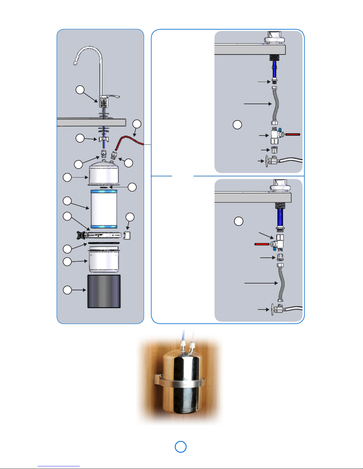
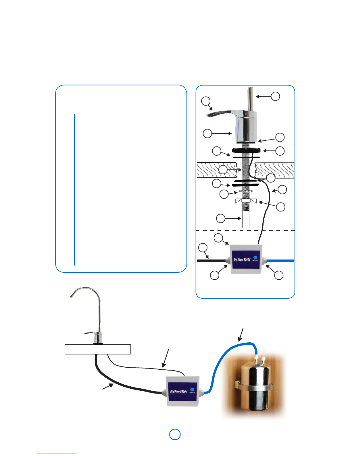
4. Prepare the Filter Monitor Unit
a. Guide the black wire (#8) from under the sink to the Filter Monitor
Unit (#14), and plug it into the top of the FMU.
b. Attach the two lter monitor adapters (#15) to the FMU (#14), one
on each side.
c. Open the FMU and pull out the battery holder. Insert two (2) AA
batteries (not included) into the battery holder, making sure to
match the + and – signs. Reinsert the battery holder.
d. Press and hold the check/reset button on the FMU for six (6)
seconds. You should hear a long audio sound, and the LED Display
Plate will ash red and then green several times.
e. Snap the cover back onto the FMU.
f. Peel off the paper backing from the hook-and-loop connector
strip, and attach one piece to the back of the FMU.
g. Select a clean, convenient mounting location on a wall beneath
the sink, allowing sufcient space for placement of the FMU. Peel
off the paper backing from the second hook-and-loop connector
strip and attach it to the desired wall location.
h. Attach the FMU to the wall using the two hook-and-loop connector
strips.
Connect the Adapta Valve
If your residence has a cold water supply line with a 3/8” or 1/2” slip joint
connection, you may use the Adapta Valve included with your system to
connect your DWS to the plumbing. The Adapta Valve assembly (MC923LF)
includes both the valve and threading adapter.
When attaching the Adapta Valve to straight pipe threads, use Teon tape
on the threads. Wrap the tape around the pipe only once.
NOTE: The Adapta Valve must be installed on the cold water line only.
10

1. Using the 3/8” conguration:
a. The 3/8” conguration is used on a water supply line with a 3/8” slip joint.
b. The 3/8” conguration is typically installed at the bottom of the riser
at the angle stop valve.
2. Using the 1/2” conguration:
a. The 1/2” conguration can be used at either the top of the riser at
the faucet pipe or at the bottom of the riser at the angle stop valve.
b. Install the 1/2” conguration at the top of the riser on a water supply
line that does not have a slip joint nut at the angle stop valve.
c. Install the 1/2” conguration at the angle stop valve if there is a
1/2” slip joint nut there.
3. Shut off the cold water supply to the faucet by rotating the angle stop
valve clockwise until the water ow is off. Place a catch basin or other
container below the faucet to catch any residual water in the pipes.
4. Disconnect the cold water riser/supply line at the angle stop valve or
cold water faucet pipe. Use an 8” adjustable wrench to rotate the slip
joint nut counterclockwise until the riser/supply line and slip joint nut
detach from either the angle stop valve or the faucet pipe.
5. Connect the Adapta Valve to the pipe from which you removed the
slip joint nut.
a. Align the Adapta Valve to either the angle stop valve or cold water
faucet pipe, making sure that the rubber washer is in place in the
Adapta Valve.
b. Use an 8” adjustable wrench to rotate the connection clockwise
until tight. DO NOT OVERTIGHTEN.
6. Connect the cold water riser/supply line with the slip joint nut to the
Adapta Valve.
a. Align the slip joint nut to the Adapta Valve.
b. Use an 8” adjustable wrench to rotate the slip joint nut clockwise
until tight. DO NOT OVERTIGHTEN.
c. Make sure that the supply line does not block the shutoff valve
on the side of the Adapta Valve. If necessary, trim the supply line
before reconnecting.
7. Conrm that the Unit Shutoff Valve attached to the Adapta Valve is in
the OFF position by rotating the handle clockwise until it stops.
11

water supply line with Adapta
Valve in 3/8” conguration
riser
angle stop valve
threading
adapter
Adapta Valve
3/8”
conguration
water supply line with Adapta
Valve in 1/2” conguration
1/2” slip joint nut
riser
angle stop valve
3/8” slip joint nut
Water supply line before installation
Adapta
Valve
Threading
Adapter
Adapta Valve
1/2”
conguration
riser
angle stop valve
12
threading
adapter

Connect the Fittings to the Housing
1. Connect the included Inlet tting (MC730-RED) to the system housing’s
labeled Inlet port. Rotate the tting clockwise, rst by hand, then using
a wrench, to tighten onto the system.
2. Connect the included Outlet tting (MC720-BLU) to the system
housing’s labeled Outlet port. Rotate the tting clockwise, rst by hand,
then using a wrench, to tighten onto the system.
Connect Tubing to the Outlet Port
1. Using wire cutters or a knife, cut
(square cut) the tip end off of the
blue plastic tubing (either connected
to the faucet or a separate piece
included with the Capacity Monitor).
Do not use scissors.
2. Fully insert the tubing into the tting
on the OUTLET port of the system
housing; the tubing should be
inserted 5/8” into the tting.
NOTE: When pushing the tubing into the tting, you will encounter some
resistance. This does not mean that the tube is fully inserted. Continue
to push rmly until the tubing is inserted as far as possible (roughly 5/8”
into the tting).
3. Pull on the tubing to make sure that it is securely connected.
Connect Tubing to the Inlet Port
1. Using wire cutters or a knife, cut
(square cut) the tip end off of the
red plastic tubing connected to the
Adapta Valve. Do not use scissors. Do
not cut more than 1/2” off of the end
of the red plastic tubing.
2. Fully insert the tubing into the tting on
the Inlet port of the system housing;
the tubing should be inserted 5/8”
into the tting.
13
blue tubing
insert
OUTLET
adapter
INLET
adapter
red tubing
insert

NOTE: When pushing the tubing into the tting, you will encounter some
resistance. This does not mean that the tube is fully inserted. Continue
to push rmly until the tubing is inserted as far as possible (roughly 5/8”
into the tting).
3. Pull on the tubing to make sure that it is securely connected.
Mount the System Under the Sink
1. Use the included screws and a Philips-head screwdriver to fasten
the included mounting bracket to the wall, ensuring it is in an upright
position. The bracket is in an upright position when the two holes on the
bracket are at the top.
2. Attach the system to the bracket:
a. Tilt the system toward the wall.
b. Slide the V-Band that runs along the center circumference of the
system up and into the upper notch on the bracket.
c. Straighten the system upright and let the bottom of the V-Band
settle into the lower notch on the bracket.
14
Connect the Tubing to the Filter Monitor Unit
(Capacity Monitor Kit ONLY)
1. Fully insert the blue plastic tubing from the Aquaversa OUTLET into the
adapter (#15) on the INLET (#5) side of the FMU; the tubing should
typically be inserted 5/8” into the adapter. The inlet side is the side from
which the arrow points away on the capacity ow device.
v-band
v-band
bracket

15
NOTE: When pushing the tubing into
the adapter, you will encounter some
resistance. This does not mean that
the tube is fully inserted. Continue to
push rmly until the tubing is inserted
as far as possible (roughly 5/8” into
the adapter).
2. Fully insert the blue plastic tubing from
the faucet into the adapter (#15) on
the OUTLET (#5) side of the FMU; the
tubing should typically be inserted
5/8” into the adapter. The outlet side
is the side to which the arrow points
on the capacity ow device.
NOTE: When pushing the tubing into
the adapter, you will encounter some
resistance. This does not mean that
the tube is fully inserted. Continue to
push rmly until the tubing is inserted
as far as possible (roughly 5/8” into
the adapter).
14
5
5 5
OUTLET
to faucet
tubing
adapter
OUTLET
Pull to check that the tubing is secure.
Insert tubing and push until you feel
resistance - at this point, the tubing is not
fully inserted. Push rmly until the tubing
is inserted as far as it will go.
INLET
to housing
insert

2
3
5
4
7
6
8
1
hose
diverter
valve
Overview & Part Numbers
Countertop Installation
(Countertop Kit Required)
Item #
1
2
3
4
5
6
7
8
9
Part #
MC6400ASBL
MCL500
MC252
MC253
CB6
MC351S
MCB500
MC240N
MC700
Part Description
Hose and Diverter Valve
Housing top
Black rubber cushion (inside housing top)
V-band with knob
Carbon Block Filter cartridge
O-ring
Housing bottom
Short acrylic base
Standard adapters (see page 7)
16

Countertop Kit Components
Included with the Countertop Kit are the following key components:
1. Acrylic Base: Used to hold the Aquaversa upright on the countertop.
The Aquaversa is placed on the acrylic base with the ports and tubing
facing down, so that the tubing can feed through the openings at the
side of the acrylic base.
2. Diverter valve: Used to connect the dual-hose from the Aquaversa to the
existing sink faucet. The diverter valve comes pre-attached to the dual-
hose, and allows selection of ltered or unltered water from the faucet.
3. Dual-hose: Used to connect the diverter valve to the Aquaversa.
Connect the Diverter Valve
1. Remove the aerator or screen (if present)
from the end of the faucet. If facing the open
end of the spout, rotate the aerator counter-
clockwise to loosen and remove.
2. Attach the diverter valve directly to the faucet
spout. If the threads of the diverter valve do
not match the threads of the faucet, use one
of the included faucet adapters to connect
the diverter valve and faucet. If facing the
open end of the spout, rotate the diverter
valve and/or adapter clockwise to tighten.
NOTE: When using a faucet adapter, the rubber washer in the adapter
always faces up toward the faucet.
a. If Your Faucet Has an Outside Thread (male connector): For many
faucets with an outside thread, the diverter valve can attach
directly to the faucet. If the diverter valve is too small to attach to
the faucet, attach the inside thread (female connector) adapter,
part# MC106 or MC105, to the faucet, and then attach the diverter
valve to the adapter.
b. If Your Faucet Has an Inside Thread (female connector): The diverter
valve cannot directly connect to a faucet with a female connector.
Attach one of the outside thread (male connector) adapters, part#
MC108, to the faucet, and then attach the diverter valve to the
adapter.
Countertop Installation
(Countertop Kit Required)
Diverter Valve
Attachment
existing
faucet
bypass
lever
hose
diverter
valve
swivel
attachment
ring
17

c. If Your Faucet Requires More Room for the
Diverter Valve Connection: Some faucets,
particularly sprayer hose faucets, require
additional room for the diverter valve
connection. If this applies, attach the long
adapter, part# MC257, to the opening of the
faucet spout/sprayer, and then attach the
diverter valve to the adapter. The Aquaversa
may need to be repositioned on the sink to
allow enough room for sprayer faucet use.
d. If the Adapters Do Not Fit Your Faucet:
Although the adapters included with your
Aquaversa allow connections with many
standard faucets, they do not cover every
type of available faucet connection. If none
of the adapters allow the diverter valve to
connect to your faucet, please contact
Multipure Customer Service at 1.800.622.9206,
ext. 175, to request part# MC109, or part#
MC719 as possible adapter solutions.
NOTE: When connected properly, the hose from the diverter valve
should lead toward the back of the faucet and sink.
3. The diverter valve features a bypass lever with a button on the left and
right sides of the diverter valve. Press the left button to bypass the DWS
and select the unltered water spout (larger opening). Turn on your
faucet to let unltered water ow out of the diverter valve and to make
sure that the diverter valve is properly connected.
4. Turn off the faucet.
Connect the Tubing to the System Housing
1. Locate the labeled Outlet tubing of the diverter valve. Insert the tubing
adapter into the labeled Outlet port of the system housing and rotate
to tighten.
2. Locate the labeled Inlet tubing of the diverter valve. Insert the tubing
adapter into the labeled Inlet port of the system housing and rotate to
tighten.
3. Making sure that the tubing feeds through the openings in the acrylic
base, place the system housing (with the ports and tubing facing down)
onto the acrylic base.
18
Diverter Valve Attachment
with adapter
*MC700 Adapters
Many installations do not
require an adapter
*MC105
*MC106
*MC108
*MC257

1. Using a paper towel or cloth, dry off all connections and the system housing.
2. Make sure that all connections are tightly secured.
3. Remove any air and loose carbon from the system.
a. On a below-sink conguration:
i. Turn the water supply back on; rotate both the Adapta Valve
shutoff valve and either the water supply Angle Stop Valve or
water shutoff valve counter-clockwise to engage the ow of
water through the pipes.
ii. Turn the handle on the Aquaversa faucet to start the ow of
ltered water.
iii. Allow water to ow through the DWS and the faucet for 30
minutes. This purges any air and loose carbon from the system.
iv. Adjust the Angle Stop Valve or water shutoff valve so that the
water ow to the drinking water faucet does not exceed the
ow rate.
NOTE: It takes approximately 20 seconds to ll a quart at 0.75
gallons per minute ow rate.
b. On a countertop conguration:
i. Press the right button on the diverter valve to select the ltered
water spout. The water will ow through the DWS and emerge
from the smaller opening on the diverter valve.
Prepare Your Drinking
Water System for Use
19
The Aquaversa can be used inline for connection to refrigerators, water
coolers, or ice makers, so that all of the water from the cold water outlet or
faucet is ltered. Multipure recommends that a professional plumber install
the system for inline use.
Inline Installation

Warranty
Multipure 90-Day Guarantee: Multipure is condent in the performance
of its Drinking water systems (DWS). If you should nd this Drinking water
system unsatisfactory, let us know within 90 days of purchase for a prompt
exchange or refund.
Multipure Warranty: Multipure warrants to the original retail customer its
DWS and components to be free of defects in material and workmanship
for use under normal care, and will repair or replace any system at no
charge (excluding transportation to Multipure Corporate Headquarters) to
the customer during the warranty period. The DWS housing is warranted for
a lifetime (provided the lter has been changed at least once per year); all
exterior hoses and attachments to the DWS are also warranted for defects
in material and workmanship for one (1) year.
Multipure solid Carbon Block Filters are warranted for defects in material and
workmanship for use under normal care. The capacity of the lter cartridge
depends upon the amount of impurities in the water to be processed.
Except as otherwise expressly provided above, Multipure makes no
warranties, express or implied, arising by law or otherwise, including
without limitation the implied warranties of merchantability and tness for
a particular purpose, to any person. This limited warranted may not be
altered, varied, or extended except by a written instrument executed by
Multipure. The remedy of repair or replacement as provided under this
limited warranty is exclusive. In no event shall Multipure be liable for any
consequential or incidental damages to any person whether occasioned
by negligence of the manufacturer, including without limitation damages
of loss of use, cost of substitution, property damage, or other monetary loss.
ii. Allow water to ow through the DWS and ltered water spout for
30 minutes. This purges any air and loose carbon from the system.
iii. Press the left button to select the unltered water spout, and
then turn off the faucet.
4. Check all connections to make sure that there are no leaks.
5. Congratulations! Your system is now ready for use!
20
Table of contents
Popular Water Dispenser manuals by other brands

Everpure
Everpure Ever Plus ESO 6 Specifications

Hague Quality Water
Hague Quality Water Maximizer 400 Installation and service manual

Honeywell
Honeywell KaltecSoft KS30E Series installation instructions

Elkay
Elkay LBWD00BKC installation manual

LAMBORGHINI CALOR
LAMBORGHINI CALOR Micro Operation manual

Primo Water
Primo Water 900129 user manual