aquilar AquiTron AT-G-ALERT Installation instructions

AquiTron AT-G-ALERT
Refrigerant Sensor
INSTALL ATION
& O P ERATION
INSTRUCTIONS

Please read these
instructions carefully
and keep them in a
safe place (preferably
close to the module)
for future reference.
These instructions
must be followed
carefully to ensure
proper operation.
AT-G-ALERT
Refrigerant Gas Sensor For
Occupied Spaces
A. GENERAL INFORMATION
The AquiTron AT-G-Alert continuously checks the ambient air of occupied spaces for refrigerant
leaks. The detector is for indoor applications. It is housed in an ABS enclosure that ts into
2-gang electrical back boxes (not included) with a minimum depth of 47mm.
Gas alarms and status messages are indicated visually by a 3-colored LED and audibly by a
buzzer. In case of an alarm and/or fault, relays switch (for example, to shut-o valves or to
activate alarm devices).
INTENDED USE
• Checks ambient air of occupied spaces for refrigerant leaks
• Intended for indoor applications
• ABS enclosure ts into most deep 2-gang electrical back boxes (not included)
• Can be operated as a stand-alone detector or connected to a BMS/BAS (Building
Management/Building Automation System)
• Designed to be installed in non-classied, non-hazardous, permanent locations.
DESIGN FEATURES
• Powered by 100 to 240 VAC, 50/60 Hz
• Gas alarms and status messages are indicated visually by a 3-colored LED and audibly by a
buzzer
• In case of an alarm and/or fault, relays can switch shut-o valves, alarm devices, or
indicators at a BMS/BAS
• Measured gas concentration, status signals and conguration information are accessible
via the Modbus RTU interface (see Section 8.9 on page 35)
• Can be calibrated and maintained non-intrusively using a magnetic wand
LEAK DETECTION SOLUTIONS
Unit 30, Lawson Hunt Industrial Park,
Broadbridge Heath, Horsham, West Sussex,
RH12 3JR
+44 (0) 1403 216100
www.aquilar.co.uk 1
INSTALLATION ITEMS
(NOT SUPPLIED)
• 47mm Back Box
TOOLS REQUIRED
• Drill or hole punch for electrical
conduit entries
• Phillips (cross-head) screwdriver
• Small at-head screwdriver
STORAGE
Keep the module in a dry place prior to
installation to avoid possible damage to
internal components.
Figure 1. AT-G-ALERT with examples of available fascia plates.

AT-G-ALERT
Refrigerant Gas Sensor
for occupied spaces
LEAK DETECTION SOLUTIONS
2
Unit 30, Lawson Hunt Industrial Park,
Broadbridge Heath, Horsham, West Sussex,
RH12 3JR
+44 (0) 1403 216100
www.aquilar.co.uk
CONTENTS
1.0 Safety
1.1 Denition of Alert Icons
1.2 General Safety Statments
1.3 Safe Connection of Electrical Devices
2.0 Components Overview
3.0 Installation
3.1 General Information for Installation
3.2 Mechanical Installation
3.3 Conguration
3.4 Electrical Installation
4.0 Operation
4.1 Start-Up
4.2 Alarm Management Function and
conguration
4.2.1 Default Alarm Function
4.2.2 Alaram Delay - Switches 2 and 3
4.2.3 Failsafe - Switch 4
4.2.4 Alarm 2 Relay - Switch 5
4.2.5 Latching Alarm State - Switch 6
4.2.6 Buzzer Disable -Switch 7
4.3 Other Switch Congurations
4.3.1 Reset (Cycle Power) - Switch 1
4.3.2 Reset to Factory Default Values -
Switch 8
4.4 Operation of Magnetic Switches,
Buzzer and LED
5.0 Maintenance
5.1 Maintenance Intervals
5.2 Adjustments
5.2.1 Introduction
5.2.2 General Procedure
5.2.3 Zero Adjustment
5.2.4 Span Adjustment
5.2.5 Bump Test
5.3 Troubleshooting
5.3.1 Failed Span Adjustment
5.3.2 Hexadecimal Format
5.3.3 Fault Conditions
5.3.4 Fatal Faults
5.3.5 Critical Gas Fault
5.3.6 Negative Gas Faults
5.3.7 Non-Critical Faults
5.4 Replacing the Sensor Module
5.5 Cleaning the Detector
6.0 Sensor Principle
7.0 Disposing of the Detector
8.0 Technical Data
8.1 Approvals
8.2 Specications for Modbus RTU
Digital communication over RS-485
8.3 Power Supply and Relay
Specications
8.4 Wiring Specications
8.5 Physical Specications
8.6 Environmental Specictions
8.7 Sensor Specications
8.8 Default Alarm Levels
8.9 Modbus Registers
8.9.1 Read Device Identications
8.9.2 Analog Input Registers
8.9.3 Analog Output Registers
8.9.4 Input Status Flags
8.9.5 Output Status Flags
9.0 Ordering Information
9.1 AT-G-Alert Refrigerant Leak Detector
Congurations
9.2 Accessories
10.0 Back Boxes and Faceplates
10.1 Introductions
10.2 Hardware Overview
10.3 Using Optional Metal Tabs
10.4 Electrical Installation
10.5 Customizing Face Plates
10.6 Calbration
11.0 Declaration of Conformity
LEAK DETECTION SOLUTIONS
3
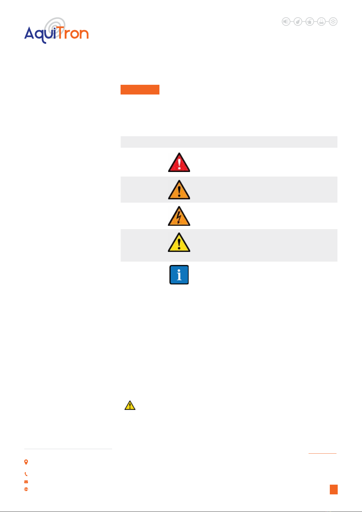
Alert Icon Description
DANGER
Indicates an imminently hazardous situation which, if not
avoided, will result in death or serious injury.
WARNING
Indicates a potentially hazardous situation which, if not
avoided, could result in death or serious injury.
WARNING
Indicates a potential electrical shock hazard which, if not
avoided, could result in death or serious injury.
CAUTION
Indicates a potentially hazardous situation which, if not
avoided, could result in physical injury or damage to the
product or environment. It may also be used to alert against
unsafe practices.
NOTICE
Indicates additional information on how to use the product.
1. SAFETY
Unit 30, Lawson Hunt Industrial Park,
Broadbridge Heath, Horsham, West Sussex,
RH12 3JR
+44 (0) 1403 216100
www.aquilar.co.uk
AT-G-ALERT
Refrigerant Gas Sensor
for occupied spaces
1.1 DEFINITION OF ALERT ICONS
The following alert icons are used in this document to highlight areas of the associated text that
require a greater awareness by the user.
1.2 GENERAL SAFETY STATEMENTS
• Before using this product, carefully read and strictly follow the instructions in the manual.
• Use the product only for the purposes specied in this document and under the conditions
listed.
• Ensure that product documentation is retained, made available, and appropriately used by
anyone operating the product.
• Comply with all local and national laws, rules, and regulations associated with this product.
• Only trained and competent personnel may use this product.
• Only trained and competent personnel may inspect, repair and maintain the product as
detailed in this manual. Maintenance that is not detailed in this manual must be completed
by Aquilar or personnel qualied by Aquilar.
• Use only genuine spare parts and accessories. Otherwise, operation may be impaired.
• Only operate the product within the framework of a risk-based alarm signaling concept.
REFRIGERANT SUFFOCATION RISK: Large refrigerant leaks into occupied spaces can
reach concentrations that pose a suocation risk to the occupants. While the AT-G-Alert
can be used to detect refrigerant leaks well below those concentrations, it is not designed
as a stand-alone safety device. Safety of the occupants must take a system design approach
including ventilation, detection, early warning, mitigation, and design redundancy among other
considerations.
↑ CONTENTS
LEAK DETECTION SOLUTIONS
4
Unit 30, Lawson Hunt Industrial Park,
Broadbridge Heath, Horsham, West Sussex,
RH12 3JR
+44 (0) 1403 216100
www.aquilar.co.uk
AT-G-ALERT
Refrigerant Gas Sensor
for occupied spaces
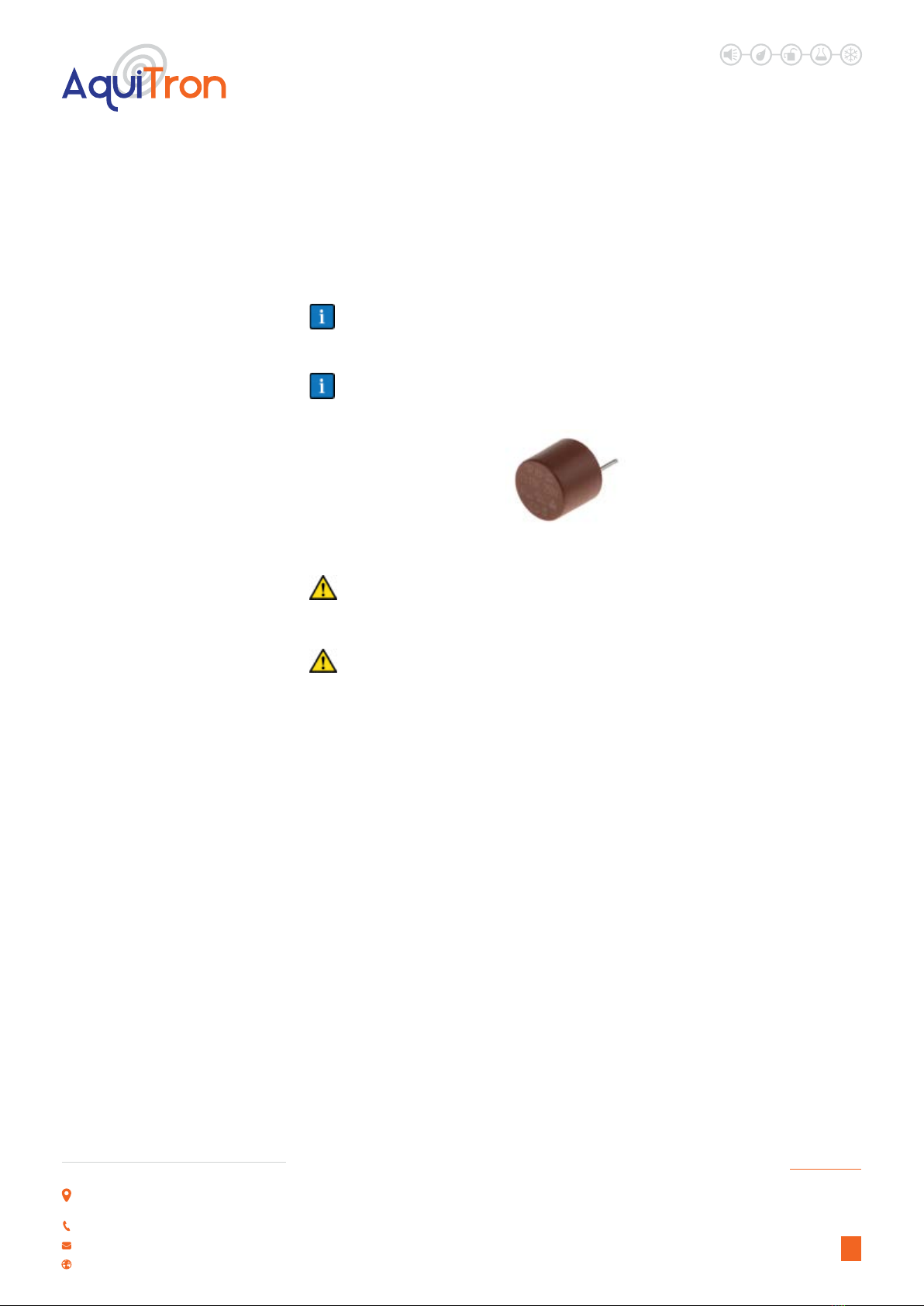
1.3 SAFE CONNECTION OF ELECTRICAL DEVICES
Before connecting this detector to electrical devices not mentioned in this manual, consult the
manufacturer or a qualied professional.
The sensor must be connected by a marked, suitably located and easily reached switch or
circuit-breaker as means of disconnection.
If replacement of either main power fuse is required, use only a TR5 Radial 3.15A 250V
slow fuse (Littlefuse 372 1315 0001 or equivalent).
Wiring must be in compliance with national and local wiring codes.
RS-485 signal cable must be insulated to the highest voltage level in the system. Protect
the RS-485 signal cable by using the supplied installation kit.
TR5 Radial 3.15A 250V
↑ CONTENTS

AT-G-ALERT
Refrigerant Gas Sensor
for occupied spaces
LEAK DETECTION SOLUTIONS
5
2. COMPONENTS OVERVIEW
Unit 30, Lawson Hunt Industrial Park,
Broadbridge Heath, Horsham, West Sussex,
RH12 3JR
+44 (0) 1403 216100
www.aquilar.co.uk
1
1
2
3
4
55
6
7
8
9
Figure 2. AT-G-ALERT Components (Front)
1. Magnetic switch poistions
1 ( on top) and 2 ( on bottom)
2. Multi-color status LED
3. Sensor type/calibration and
ID/serial number labels
4. Mounting slots
5. Testing points - access holes x 2
6. Sensor alignment ribs
7. Replacement sensor module
8. Direction arrows x2 for proper mounting
9. Firmware version and part number/
calibration labels
↑ CONTENTS
LEAK DETECTION SOLUTIONS
6
Unit 30, Lawson Hunt Industrial Park,
Broadbridge Heath, Horsham, West Sussex,
RH12 3JR
+44 (0) 1403 216100
www.aquilar.co.uk
10. Conguration DIP switches (1-8)
11. Relay 1 output connectors (low gas
alarm)
12. Relay 2 output connectors (high gas
alarm or fault)
13. Power connectors
14. Modbus serial communications
connectors
15. Wiring harness
AT-G-ALERT
Refrigerant Gas Sensor
for occupied spaces
12
13
14
15
10
11
↑ CONTENTS

LEAK DETECTION SOLUTIONS
7
Unit 30, Lawson Hunt Industrial Park,
Broadbridge Heath, Horsham, West Sussex,
RH12 3JR
+44 (0) 1403 216100
www.aquilar.co.uk
AT-G-ALERT
Refrigerant Gas Sensor
for occupied spaces
3. INSTALLATION
3.1 GENERAL INFORMATION FOR INSTALLATION
Every detail of installation location is critical to ensure overall system performance and
eectiveness. Strict compliance and considerable thought must be given to every detail of the
installation process, including, but not limited to the following:
• Regulations as well as local, state, and national codes that govern the installation of gas
detection equipment
• Electrical codes that govern the routing and connection of electrical power and signal
cables to gas detection equipment
• The full range of environmental conditions to which the detectors will be exposed (refer
to section 6: Sensor Principle on page 28 for more information on ambient conditions and
cross-sensitivity)
• The physical characteristics of the gas or vapor to be detected
• The specics of the application (e.g., possible leaks, air movement/draft, etc.)
• The degree of accessibility required for maintenance purposes
• The types of optional equipment and accessories that will be used with the system
• Any limiting factors or regulations that would aect system performance or installations
• Wiring details, including the following:
• Wiring must be connected as indicated in this manual.
• The wiring for power and relays must be selected and fused according to the rated
voltages, currents, and environmental conditions.
• If stranded conductors are used, a ferrule should be used.
• A switch or circuit breaker must be included in the installation.
• The switch or circuit breaker must be suitably located and easily reached.
• The switch or circuit breaker must be marked as the disconnect device for the
equipment.
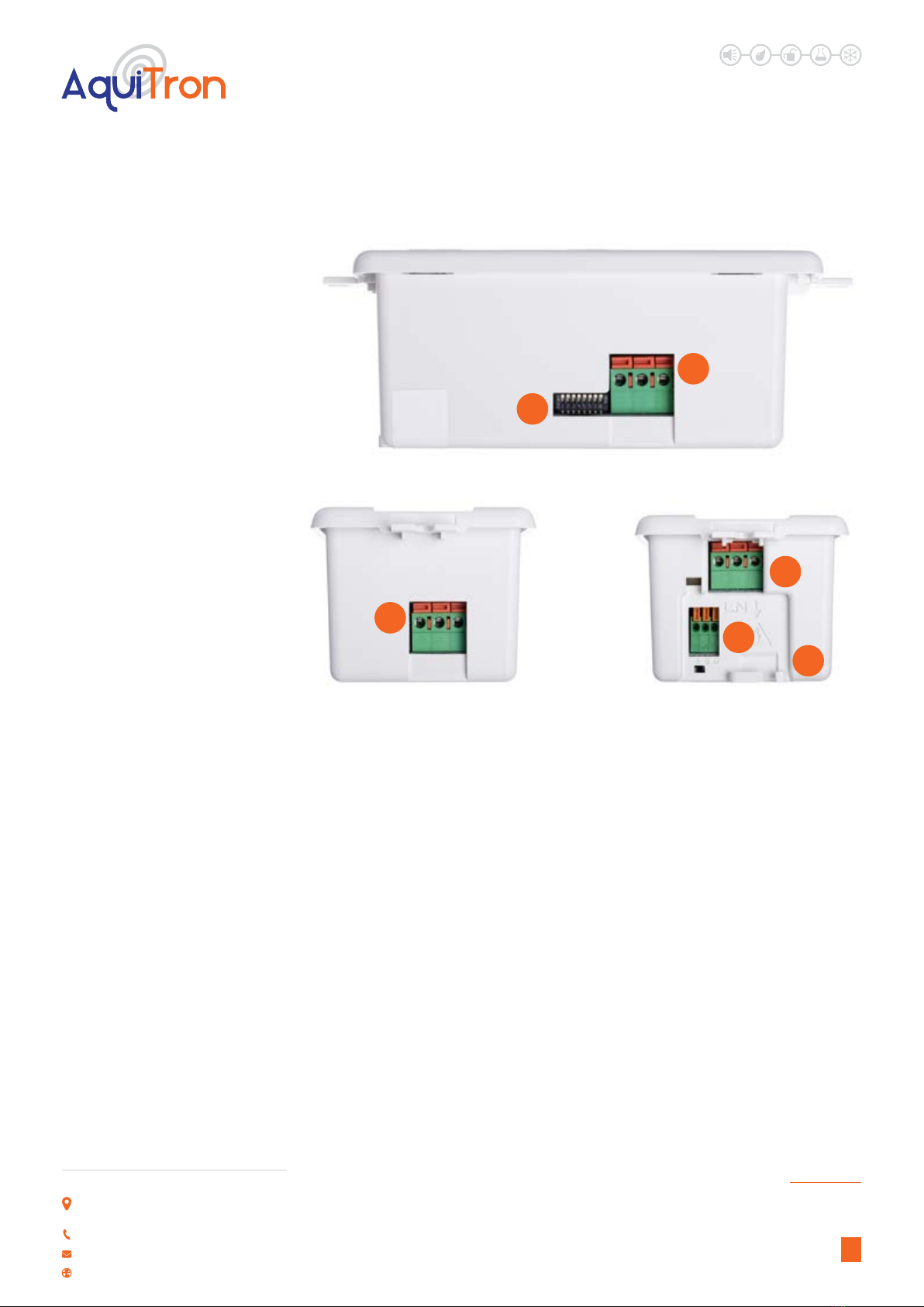
3.2 MECHANICAL INSTALLATION
• The detector ts in 47mm deep 2-gang electrical back boxes (not included)
• The detector must be accessible for maintenance (e.g., adjustment)
• The access pathway of the refrigerant gas to the sensor must not be obstructed
• The detector should be installed about 4 to 6 inches (100 to 150 mm) above the oor level
Figure 4. Typical AT-G-ALERT supported backboxes
↑ CONTENTS
LEAK DETECTION SOLUTIONS
8
Unit 30, Lawson Hunt Industrial Park,
Broadbridge Heath, Horsham, West Sussex,
RH12 3JR
+44 (0) 1403 216100
www.aquilar.co.uk
AT-G-ALERT
Refrigerant Gas Sensor
for occupied spaces
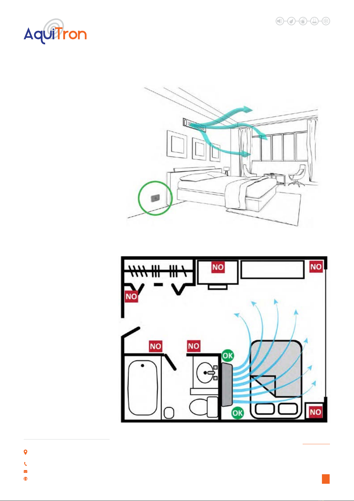
Figure 6. Recommended Installation Locations
Figure 5. Typical AT-G-ALERT Installation in an Occupied Space Application
↑ CONTENTS
LEAK DETECTION SOLUTIONS
9
Unit 30, Lawson Hunt Industrial Park,
Broadbridge Heath, Horsham, West Sussex,
RH12 3JR
+44 (0) 1403 216100
www.aquilar.co.uk
AT-G-ALERT
Refrigerant Gas Sensor
for occupied spaces
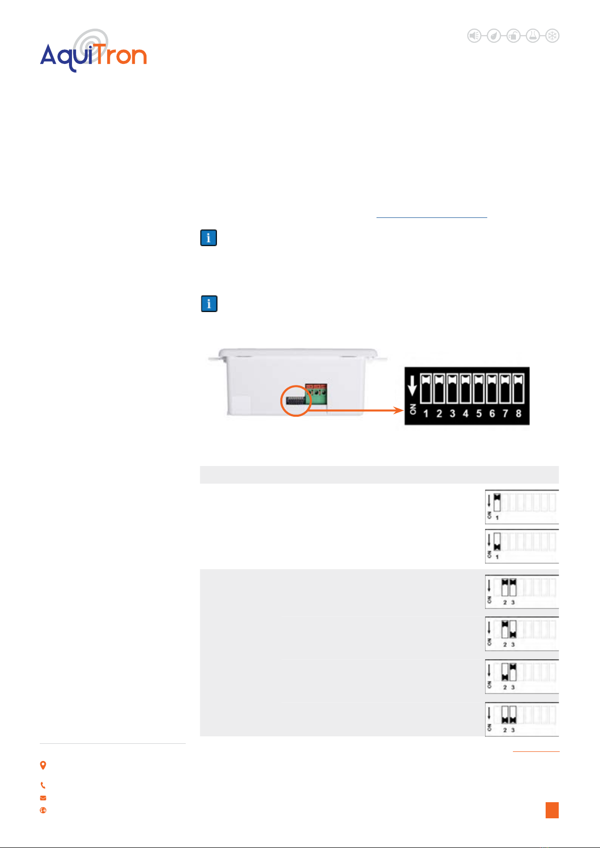
Figure 7. Switches for Conguring the AT-G-Alert
3.3 CONFIGURATION
Conguration is accomplished via switches or from a Remote Terminal Unit (RTU) on a Modbus
serial communications network. Review the default settings to determine if they are suitable for
your particular application. If default values are not suitable, change the conguration using the
DIP switches, or via the Modbus interface. A summary of switches is shown below. For details
on Modbus communications registers, refer to Section 8.9: Modbus Register.
By default, switch congurations supersede Modbus congurations. Use Modbus register
2007 (Modbus Precedence over DIP Switch Settings) to change this precedence.
Changes of congurations will not take eect until the detector is restarted (i.e., toggling switch
1 or cycling power).
For a proper reset, switch 1 must be toggled (ON then OFF). If it is left ON, the detector is
held in reset mode and will not function correctly until the switch is returned to the OFF
position.
Switch Function Options and Description Positions
1Restart
O = Normal Operation (default)
On = Restart AT-G-ALERT (must return switch to OFF
position)
2, 3 Alarm ON
Delay
O, O = No delay (default)
O, On = 5 minute delay
On, O = 10 minute delay
On, On = 15 minute delay
↑ CONTENTS
LEAK DETECTION SOLUTIONS
10
Unit 30, Lawson Hunt Industrial Park,
Broadbridge Heath, Horsham, West Sussex,
RH12 3JR
+44 (0) 1403 216100
www.aquilar.co.uk
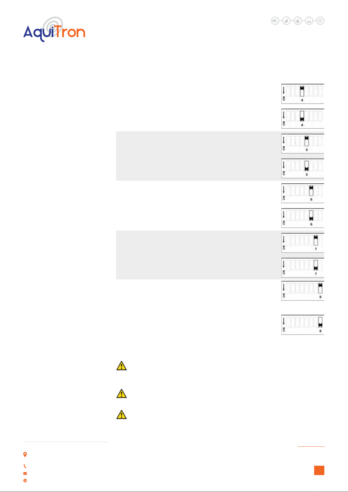
4
Failsafe
Relay
Selection
O = Normal Relay Operation (default)
On = Failsafe Relay Operation
5
Relay
2 Fault
Indication
O = High Alarm or Fault (default)
On = High Alarm Only
6Alarm
Latching
O = Alarms automatically reset (default)
On = Alarms latch and require manual reset
7Buzzer
Disable
O = Buzzer enabled (default)
On = Buzzer disabled
8
Reset
Detector
Settings
to Factory
Default
Values
O = Normal operation
On = Used in reset procedure for resetting Modbus
registers to their factory default values (see section
4.3.2 on page 21 for reset information and section
8.9 on page 36 for Modbus registers and default
values).
AT-G-ALERT
Refrigerant Gas Sensor
for occupied spaces
3.4 ELECTRICAL INSTALLATION
Caution: A switch or circuit breaker must be included in the installation. The switch or
circuit breaker must be suitably located and easily reached, and it must be marked as the
disconnect device for the equipment.
Caution: Ensure all wiring connections are made before applying power.
Caution: This product uses semiconductors which can be damaged by electrostatic
discharge (ESD). When handling the printed circuit boards (PCBs), observe proper ESD
precautions so that the electronics are not damaged.
↑ CONTENTS

LEAK DETECTION SOLUTIONS
11
Unit 30, Lawson Hunt Industrial Park,
Broadbridge Heath, Horsham, West Sussex,
RH12 3JR
+44 (0) 1403 216100
www.aquilar.co.uk
AT-G-ALERT
Refrigerant Gas Sensor
for occupied spaces
Caution: RS-485 signal cable must be insulated to the highest voltage level in the system.
Protect the RS-485 signal cable by using the supplied installation kit.
Caution: Wiring must be in compliance with national and local wiring codes.
Notice: When inserting wire into the terminal, release the spring clamp by pushing the
release latch back.
Description of ELECTRICAL Installation
1. Remove fascia by loosening the set screw.
2. Observing proper polarity, connect wires for power to the appropriate terminals.
Power:
100Vac-240Vac
Earth / Ground
Label:
L - Vac Line
N - Vac Neutral
G - Vac earth ground
Figure 8. Wiring Power
4. Observing proper polarity, connect normally closed (NC) common (COM), and normally open
(NO) wires for relays to the appropriate terminals.
Figure 9. Wiring Relay 1 (Low Gas Alarm) and Relay 2 (High Gas Alarm or Fault)
↑ CONTENTS
LEAK DETECTION SOLUTIONS
12
Unit 30, Lawson Hunt Industrial Park,
Broadbridge Heath, Horsham, West Sussex,
RH12 3JR
+44 (0) 1403 216100
www.aquilar.co.uk
AT-G-ALERT
Refrigerant Gas Sensor
for occupied spaces
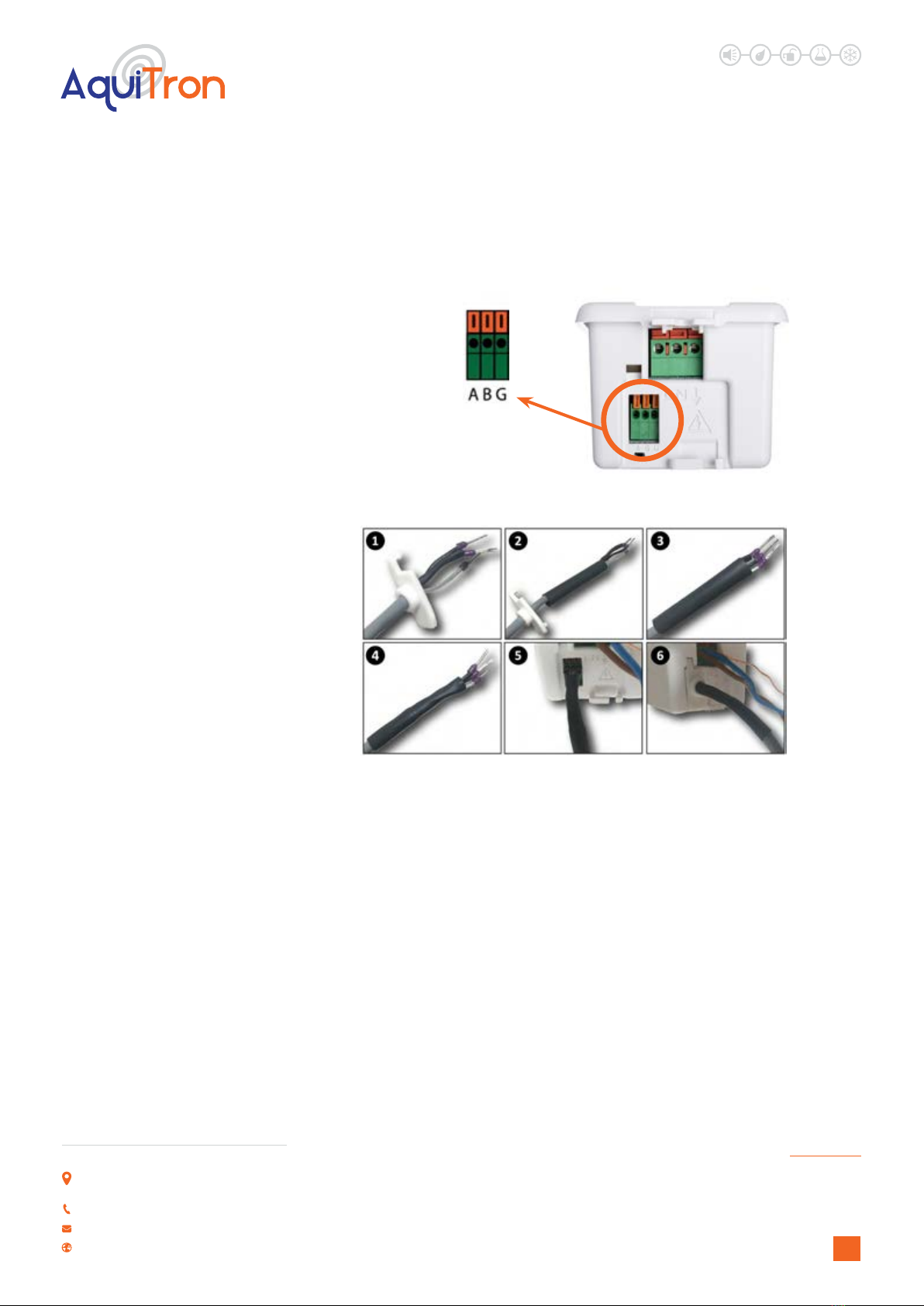
5. Observing proper polarity, make the Modbus connections as follows, using the gures below
for reference.
Label:
A - RS-485 “A” (non-
inverted)
B - RS-485 “B” (inverted)
G - RS-485 shield
Figure 10. Modbus Wiring Terminals
1. Prepare signal cable and put boot over the signal cable (1).
2. Add ferules if required (2).
3. Apply 10 cm piece of shrink wrap as close to the wire ends/ferules
as possible while leaving some free wire to allow connection to the
detector (3).
4. Heat the shrink wrap (4).
5. Connect signal wires/ferules to the detector (5).
6. Slide rubber boot along the wire and shrink wrap assembly and
connect it to the detector (6).
Figure 11. Details for Connecting Modbus Communications Wiring
6. Conrm conguration of switches. Refer to Section 3.3 on page 9.
↑ CONTENTS
7. Place detector into electrical back box (not included).
8. Put cover plate on and secure through mounting screws.
LEAK DETECTION SOLUTIONS
13
Unit 30, Lawson Hunt Industrial Park,
Broadbridge Heath, Horsham, West Sussex,
RH12 3JR
+44 (0) 1403 216100
www.aquilar.co.uk
AT-G-ALERT
Refrigerant Gas Sensor
for occupied spaces
4.2 ALARM MANAGEMENT FUNCTION AND CONFIGURATION
The AT-G-Alert oers several dierent ways how the detector behaves in case of a refrigerant
alarm. The alarm manager can either be congured through the switches or the Modbus
interface.
Figure 15. Default Alarm Generation
4.1 STARTUP
1. Switch power on.
2. Observe start-up sequence and warm-up
phase.
• Green LED will blink at 0.5 Hz for about 5
minutes
• Modbus ag for warm-up is set
• Buzzer is o
• Relay state is “no alarm”
4. OPERATION
3. Observe normal operation
• Green LED is steady on
• Buzzer is o
• Relay state is “no alarm”
4. A bump test is required following
installation to verify instrument
functionality. (See section 5.2.5)
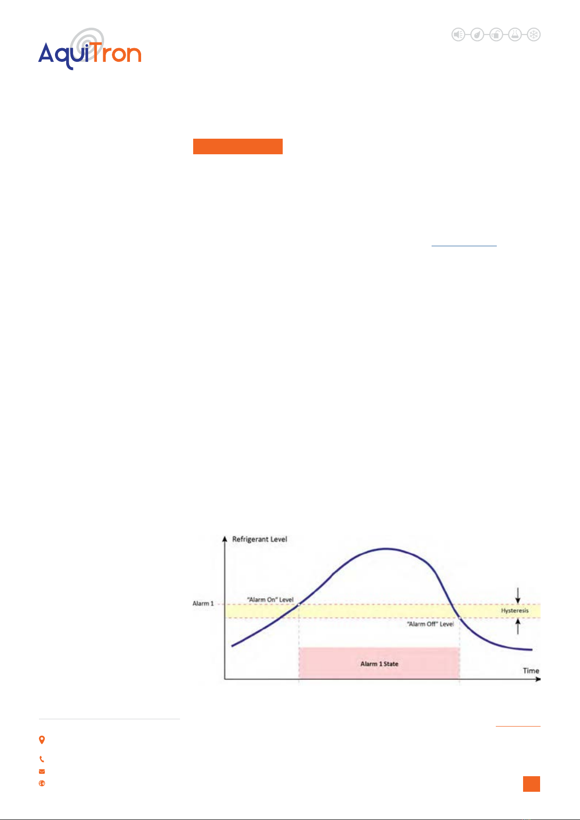
4.2.1 Default Alarm Function
If the refrigerant concentration raises above
the alarm 1 set-point:
• The LED ashes red with 0.5 Hz
• The buzzer beeps at 0.5 Hz
• The alarm 1 relay changes state
• The Modbus alarm 1 ag is set.
Once the alarm 1 condition is no longer
present and below the hysteresis value
(imposed to avoid relay chatter), the detector
returns to normal operation.
If the refrigerant concentration raises above
the alarm 2 set-point:
• The LED ashes red with 2 Hz.
• The buzzer beeps at 2 Hz
• The alarm 2 relay changes state
• The Modbus alarm 2 ag is set.
Once the alarm 2 condition is no longer
present and below the hysteresis value
(avoiding relay chatter), the detector returns
to alarm 1 state.
↑ CONTENTS
LEAK DETECTION SOLUTIONS
14
Unit 30, Lawson Hunt Industrial Park,
Broadbridge Heath, Horsham, West Sussex,
RH12 3JR
+44 (0) 1403 216100
www.aquilar.co.uk
AT-G-ALERT
Refrigerant Gas Sensor
for occupied spaces
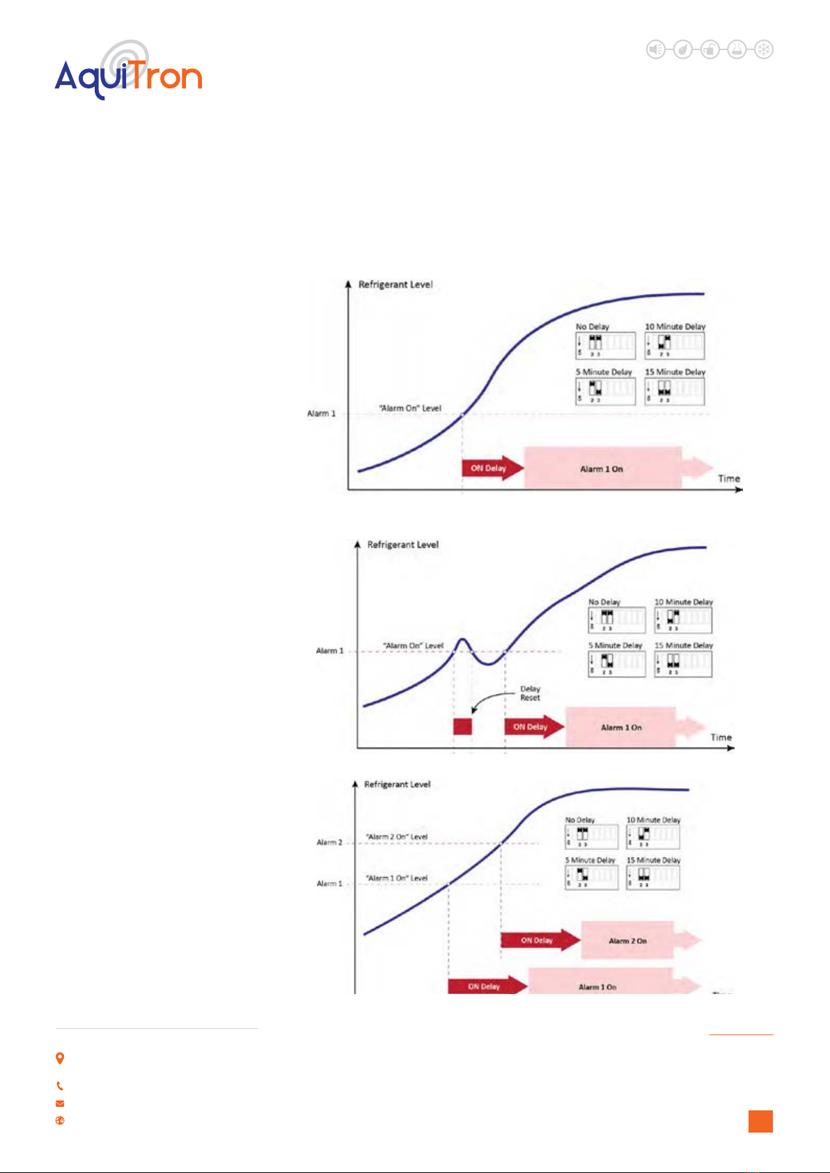
4.2.2 Alarm Delay – Switches 2 and 3
To avoid premature alarms, ensuring the presence of refrigerant for a certain amount of time,
the triggering of the alarm can be delayed for a short period of time. Unless the alarm condition
is present for at least the delay time, the alarm will not be triggered.
Figure 16. Alarm ON Delay (Alarm Condition Must Be Present for at Least the Programmed Time)
Figure 17. Alarm ON Delay (A Shorter Delay Time Is Disregarded)
Figure 18. Alarm ON Delay for Multiple Alarm Levels
↑ CONTENTS
LEAK DETECTION SOLUTIONS
15
Unit 30, Lawson Hunt Industrial Park,
Broadbridge Heath, Horsham, West Sussex,
RH12 3JR
+44 (0) 1403 216100
www.aquilar.co.uk
AT-G-ALERT
Refrigerant Gas Sensor
for occupied spaces
4.2.3 Failsafe – Switch 4
If ON, the relays will change state whenever either of the following occurs.
• Power loss
• Alarm condition.
4.2.4 Alarm 2 Relay – Switch 5
If ON, the relay will only change state as a result of an alarm condition. In the default
conguration, Relay 2 will also indicate critical faults.
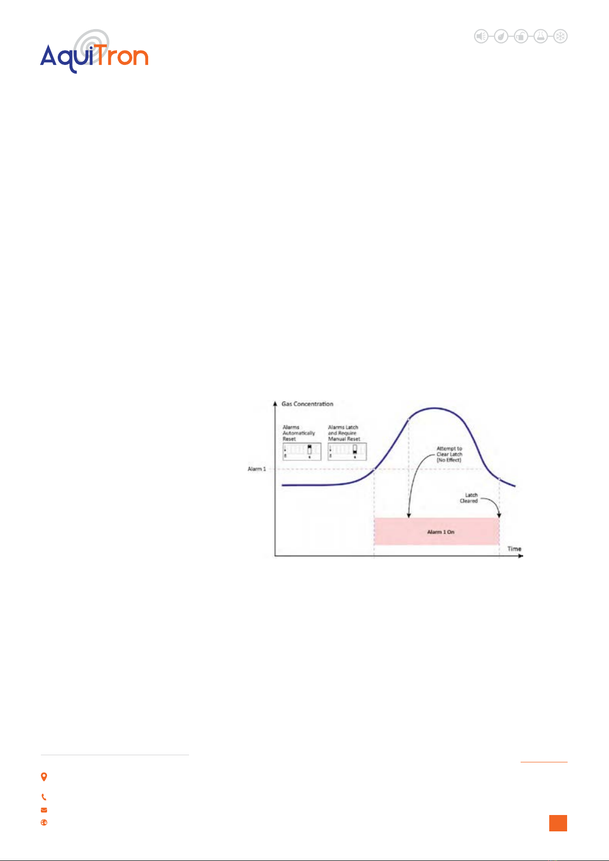
4.2.5 Latching Alarm State – Switch 6
If ON, the relay and Modbus ag will not change state until the concentration is below the alarm
level and it is acknowledged. The acknowledgement can either happen by tapping and holding
the magnetic wand for 5 seconds to the switch indicated as ( • • ) or by changing the respective
Modbus ag to 0.
In the default conguration the alarms will automatically reset when the gas level is below the
alarm thresholds.
Figure 19. Latched Alarm Requiring Acknowledgement and Gas Concentration below Alarm Level
4.2.6 Buzzer Disable – Switch 7
If ON, the buzzer is disabled and will not sound.
4.3 OTHER SWITCH CONFIGURATIONS
4.3.1 Reset (Cycle Power) - Switch 1
Use the following procedure to cycle power to the AT-G-Alert.
1. Move switch 1 to the ON position.
2. Move switch 1 to the OFF position.
3. Power is cycled to the AT-G-Alert.
↑ CONTENTS
LEAK DETECTION SOLUTIONS
16
Unit 30, Lawson Hunt Industrial Park,
Broadbridge Heath, Horsham, West Sussex,
RH12 3JR
+44 (0) 1403 216100
www.aquilar.co.uk
AT-G-ALERT
Refrigerant Gas Sensor
for occupied spaces
4.3.2 Reset to Factory Default Values - Switch 8
Use the following procedure to reset all congurable Modbus registers to their factory default
values.
1. Ensure that the detector is o. If the detector is on, turn o power.
2. Set switch 8 to ON.
3. Turn on the detector. The buzzer will be ON and the LED will be OFF.
4. Set switch 8 to OFF. The buzzer will be OFF and the LED will be OFF.
5. Using the magnetic wand, hold magnetic switch 1 ( •) for 60 seconds. LED is GREEN during
this period.
6. Wait for the LED to changes to ORANGE.
7. Reset the detector by cycling power (by toggling switch 1).
8. Detector will start-up as normal and re-read all switch settings.
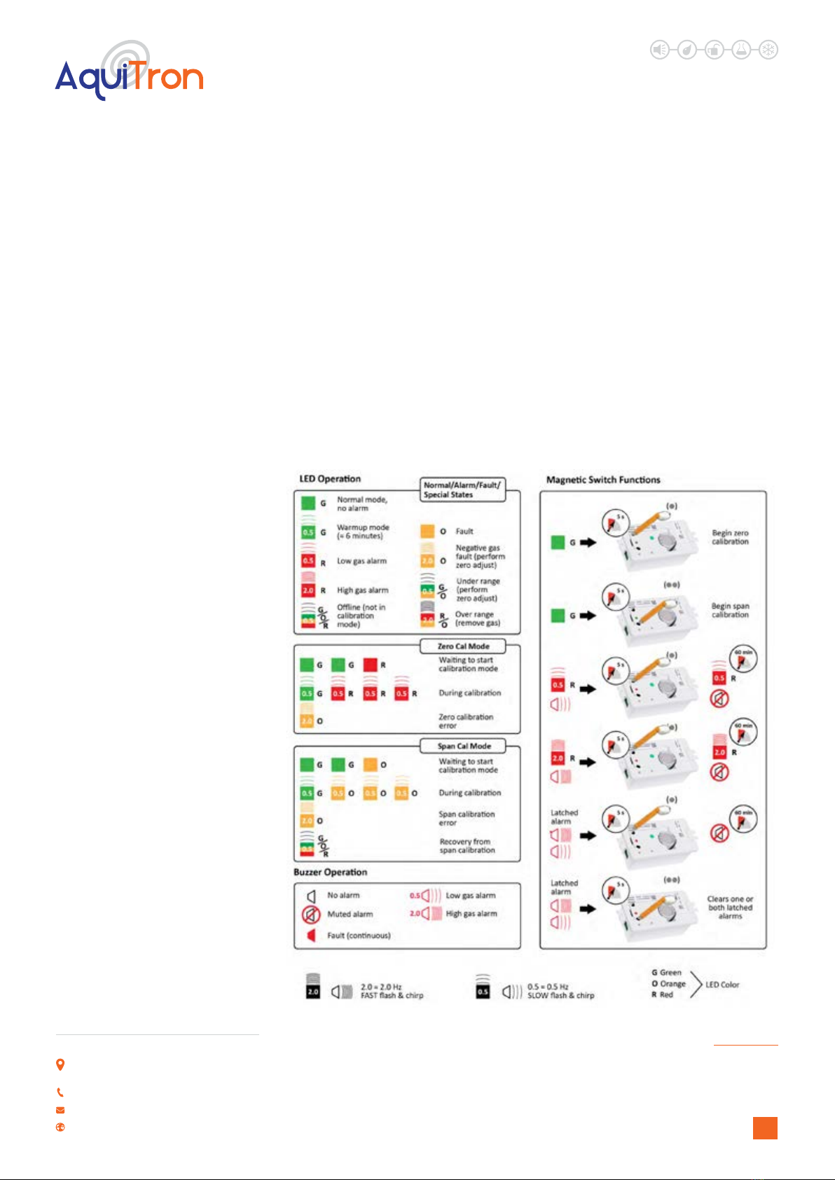
4.4 OPERATION OF MAGNETIC SWITCHES, BUZZER AND LED
Figure 20. Operation of Magnetic Switches, Buzzer, and LED
↑ CONTENTS
LEAK DETECTION SOLUTIONS
17
Unit 30, Lawson Hunt Industrial Park,
Broadbridge Heath, Horsham, West Sussex,
RH12 3JR
+44 (0) 1403 216100
www.aquilar.co.uk
AT-G-ALERT
Refrigerant Gas Sensor
for occupied spaces
5.0 MAINTENANCE
5.1 MAINTENANCE INTERVALS
During Commissioning:
• Check calibration.
• Check LEDs for proper operation.*
• Check for proper buzzer and relay operation.*
• Check signal transmission to the BMS/BAS (central controller) if connected.*
During Commissioning:
• Inspection by trained service personnel.
• Check LEDs for proper operation.*
• Check for proper buzzer and relay operation.*
• Calibrate the sensor or contact Aquilar for sensor exchange with factory-calibrated sensor.
As Required:
• Replace sensor module(s) (see page 27).
*These can be activated via Modbus commands.
5.2 ADJUSTMENTS
5.2.1 Introduction
Warning: Breathing Hazard: Calibration gas must not be inhaled See appropriate Safety
Data Sheets. Calibration gas should be vented into a fume hood or to the outside of the
building.
Warning: Zero First, Then Span: For proper operation, never adjust the span before
completing a zero adjustment. Performing these operations out of order will cause faulty
calibration.
Warning: Aquilar recommends calibrating detectors within the application-specic
conditions and with target gas. This method of zeroing the detector in the application
environment and performing a target gas calibration is more accurate. A surrogate gas
calibration may only be performed as an
Notice: The sensor should be fully warmed-up (at least 2 hours, 24 hours recommended).
Notice: When entering the functions for zero or span adjustment, the detector will
automatically enter OFFLINE mode, and will remain OFFLINE until either the OFFLINE
mode is canceled by tapping the respective magnetic switch, or the OFFLINE mode times out
within 6 minutes (typical) after the adjustment has ended.
↑ CONTENTS

LEAK DETECTION SOLUTIONS
18
Unit 30, Lawson Hunt Industrial Park,
Broadbridge Heath, Horsham, West Sussex,
RH12 3JR
+44 (0) 1403 216100
www.aquilar.co.uk
AT-G-ALERT
Refrigerant Gas Sensor
for occupied spaces
5.2.2 General Procedure
1. Verify that the detector is NOT in alarm and does not have a fault condition (i.e., it must not
have a continuous orange LED).
2. Verify that the calibration gas is in a balance of air, not Nitrogen (N2).
3. Fit testing hood to the fascia plate (7) or base plate (6) (see below).
4. Check switch 8 to OFF. The buzzer is OFF and the LED is OFF.
5. Connect the tubing to the barbed ttings of the pressure regulator and testing hood.
6. Verify that gas ow is approximately 0.3 to 1.0 L/min.
7. If operation is intended to be at higher altitudes, the factory calibration will result in a reading
lower than the reading at sea level (reduced partial pressure). A new span adjustment is
recommended if the altitude or the ambient pressure is changed. The factory calibration is
set to sea level.
8. Always perform a zero adjustment before a span adjustment.
Warning: Ambient air can be used to zero the sensor instead of synthetic air
only if the area is known to be free of the target gas or any gas to which the
sensor may be cross- sensitive. In this case, no cylinder or testing hood is needed for
the zero adjustment.
Figure 21. Calibration Assembly
1. Testing hood
2. Flow meter
3. Pressure regulator
4. Calibration gas
5. Tubing
6. Calibration from base plate (with test point access)
7. Calibration from fascia plate
1
2
4
5
3
7
6
↑ CONTENTS

LEAK DETECTION SOLUTIONS
19
Unit 30, Lawson Hunt Industrial Park,
Broadbridge Heath, Horsham, West Sussex,
RH12 3JR
+44 (0) 1403 216100
www.aquilar.co.uk
AT-G-ALERT
Refrigerant Gas Sensor
for occupied spaces
5.2.3 Zero Adjustment ( ... continued for General Procedure)
9. Tap and hold ( • ) for more than 5 seconds. The LED will blink green-green-red to indicate
the detector is ready. Verify that the calibration gas is in a balance of air, not Nitrogen (N2).
10. Apply synthetic air (or use ambient air per the warning above).Set switch 8 to OFF. The
buzzer will be OFF and the LED will be OFF.
11. Tap ( • ) within 30 seconds to conrm start of calibration. Otherwise the detector will time-
out and return to normal operation.
12. As the process progresses, the LED will blink green-red, green-red-red, green-red-red-red,
etc.
• To abort calibration, tap and hold ( • ) for >5 seconds, turn o gas ow and remove the
testing hood. The detector will return to normal operation.
• If calibration is successful (green LED), skip to step 15.
• If calibration is unsuccessful (orange LED blinks @ 2 Hz), then tap ( •) to discard the
calibration attempt, and see Section 5.3 on page 26 for troubleshooting.
13. Turn o gas ow from synthetic air
14. Replace synthetic air tank with calibration gas tank in preparation for span adjustment.
5.2.4 Span Adjustment
15. Tap and hold ( ••) for >5 seconds. The LED will blink green-green-orange when the detector
is ready.
16. Apply span gas in the concentration listed on the cal gas concentration label (beneath the
detector’s cover plate). This may require the temporary removal of the bezel and cover plate
to see the label.
17. Tap ( • • ) within 30 seconds to conrm initiation of the calibration. Otherwise the detector
will time-out and return to normal operation.Turn o gas ow from synthetic air
18. As the calibration process progresses, the LED will blink green-orange, green-orange-
orange, green-orange-orange-orange, etc.
• To abort calibration, tap and hold ( • • ) for >5 seconds, turn o gas ow and remove the
testing hood. The detector will return to normal operation.
• If calibration is successful, the LED will blink green-orange-red indicating ‘oine’. Turn o
gas ow and remove the testing hood. After 6 minutes the detector will return to normal
operation.
• If calibration is unsuccessful (orange LED blinks @ 2 Hz), then tap ( • • ) to discard the
calibration attempt, and see Section 5.3 on page 21 for troubleshooting. Turn o gas
ow and remove the testing hood. After 6 minutes the detector will return to normal
operation.
5.2.5 Bump Test
A bump test is a live test of a system to verify that the detector responds to gas and all
connected alarm devices, BMS, etc. are operating accordingly. In this case it is necessary that
all involved persons are informed about the test and certain alarms might have to be inhibited
(e.g., shutdown valves, notication of authorities, etc.).
1. Inform building personnel of test so that certain alarms may be inhibited (e.g.,
shutdown valves, notication of authorities, etc.).
↑ CONTENTS
Other manuals for AquiTron AT-G-ALERT
1
Other aquilar Accessories manuals


