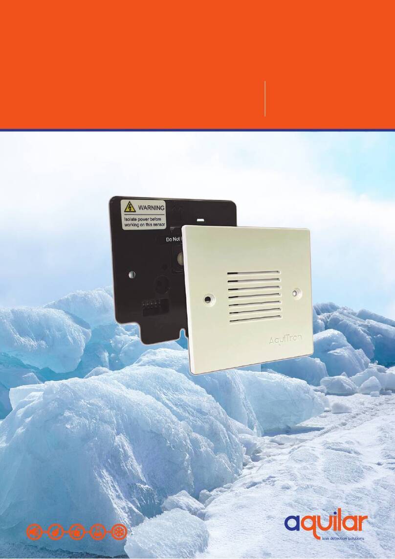
aquilar AquiTron AT-G-ALERT-C User manual

1100
-2184 Rev 0 1

1100-2184 Rev 0 2
Table of Contents
1!Introduction 4!
1.1!About this Manual 4!
1.2!Iconography 4!
1.3!General Safety Statements 5!
2!Product Description 6!
2.1!AT-G-ALERT-C Core Functions 6!
2.1.1!Home 6!
2.1.2!Navigation Buttons 7!
2.1.3!Status Icons 7!
2.1.4!Floor List 7!
2.1.5!Room/Device list (each floor) 8!
2.1.6!Settings 9!
2.2!System Components 10!
2.2.1!AT-G-ALERT-C Refrigerant Leak Monitor 10
2.2.1!AT-G-ALERT-C Refrigerant Leak Monitor 10!
2.2.2!AT-G-ALERT Refrigerant Leak Detector 10!
2.2.3!Ethernet Network Switch 10!
2.2.4!Gateway 10!
2.2.5!Modbus EZ-Wire Kit 10!
2.3!Hardware Overview 10!
3!Installation 12!
3.1!Network Overview 12!
3.2!Floorplan Spreadsheet (CSV) 14!
3.3!Gateway IP Address 15!
3.4!Hardware Installation 19!
3.5!Connecting Relays: Alarm, Fault 19!
3.6!Battery for Persistent Memory 20!
3.7!Connecting Ethernet Gateways 20!
3.8!Connecting AT-G-ALERT 22!
3.9!Upload Floorplan Spreadsheet 23!
3.10!Commissioning 23!
3.11!Method 1: Modbus ID Auto-assign 24!

1100-2184 Rev 0 3
3.12!Method 2: Set Modbus ID Manually 28!
4!Operation 30!
4.1!Overview of Normal Operation 30!
4.2!Alarm Detection 30!
4.3!Fault Detection 31!
4.4!Communication (Comm.) Error 31!
4.5!Event History 33!
4.6!Service Mode Screen 35!
5!Additional Information 36!
5.1!Disposing of the Instrument 36!
5.2!Service Center Locations 36!

1100-2184 Rev 0 4
1 Introduction
1.1 About this Manual
Thank you for investing in an AquiTron AT-G-ALERT-C Refrigerant Leak Monitor. To ensure
operator safety and the proper use of the system, please read the contents of this manual for
important information on the operation and maintenance of the instrument.
1.2 Iconography
Alert
Icon
Description
Danger
An imminently hazardous situation which, if not avoided, will result in death or serious
injury.
Warning
A potentially hazardous situation which, if not avoided, could result in death or serious
injury.
Warning
Potential electrical shock hazard which, if not avoided, could result in death
or serious injury.
Caution
A potentially hazardous situation which, if not avoided, could result in physical injury or
damage to the product or environment. It may also be used to alert against unsafe
practices.
Important
Additional information on how to use the product.

1100-2184 Rev 0 5
1.3 General Safety Statements
DANGER: This product HAS NOT been designed for use in hazardous locations. Failure to comply may
result in personal injury or death.
WARNING: NEVER connect the product’s 24V DC inputs directly to AC power supply.
WARNING: DO NOT apply power until all wiring has been completed.
CAUTION: The protection provided by this product may become impaired if it is used in a manner not
specified by the manufacturer. Modifications to this instrument, not expressly approved, will void the
warranty.
CAUTION: DO NOT continue to use this equipment if there are any symptoms of malfunction or failure.
In the case of such occurrence, de-energize the power supply and contact Aquilar Ltd.
IMPORTANT: Before using this product, carefully read and strictly follow the instructions in the manual.
Ensure that all product documentation is retained and available to anyone operating the instrument.
IMPORTANT: The AT-G-ALERT-C must be installed by a suitably qualified technician who will install this
unit in accordance with these instructions and the standards in their industry / country. This document is
only intended as a guide, and the manufacturer bears no responsibility for the installation or operation of
this unit.
IMPORTANT: Comply with all local and national laws, rules, and regulations associated with this
equipment. Operators should be aware of the regulations and standards in their industry / locality for the
operation of the AT-G-ALERT-C.

1100-2184 Rev 0 6
2 Product Description
The AT-G-ALERT-C Refrigerant Leak Monitor provides centralised monitoring and alarming
for multi-occupant applications utilising the AT-G-ALERT Refrigerant Leak Detectors. The
AT-G-ALERT-C continuously monitors all connected devices for alarm and fault conditions
and will provide alerts via the integrated colour touchscreen, audible buzzer, and built-in
relays.
2.1 AT-G-ALERT-C Core Functions
Monitor a network of connected AT-G-ALERT refrigerant leak detectors for the following:
• High or low PPM alarm events
• Hardware faults
• Network connectivity
The AT-G-ALERT-C controller will respond to these events as follows:
• Alarm – activates the alarm relay, flashes the screen to RED, activates the
audible buzzer
• Fault – activates the fault relay, flashes the screen to AMBER, activates the
audible buzzer
• Communication Error – flashes the screen to BLUE, indicates warning on
screen with the specific unit(s)
2.1.1 Home
After inactivity on the touchscreen, the system will always revert to the Home screen.
When no alarms or warnings are active, this screen resumes a System Normal state.
Figure 1 - Home Screen

1100-2184 Rev 0 7
2.1.2 Navigation Buttons
Most screens have the following navigation buttons:
2.1.3 Status Icons
Each floor and room will use the following status icons:
2.1.4 Floor List
Each floor will designate the highest severity status from all devices on that floor.
Icon
Icon Name
Home
Alarm list
Fault list
Comm error
Floor list
Icon
Icon Name
Alarm
Fault
Comm error
Normal
Not yet commissioned

1100-2184 Rev 0 8
2.1.5 Room/Device list (each floor)
Detailed view for each AT-G-ALERT / room in the system grouped on a given floor.
Figure 2 - Floor List
Figure 3 - Room/Device List

1100-2184 Rev 0 9
2.1.6 Settings
Use the settings screen for system configuration changes.
To access the Settings screen, tap the gear icon.
This screen is passcode protected to avoid unintentional changes.
If not already logged in, the Passcode prompt will appear.
Enter the passcode for the AT-G-ALERT-C controller to unlock and allow changes.
The default system passcode for the AT-G-ALERT-C is 6388.
Figure 4 - System Settings
Figure 5 - Passcode

1100-2184 Rev 0 10
2.2 System Components
2.2.1 AT-G-ALERT-C Refrigerant Leak Monitor
The AT-G-ALERT-C Refrigerant Leak Monitor (AT-G-ALERT-C) provides centralized
alarming and monitoring for all connected AT-G-ALERT Leak Detectors.
2.2.2 AT-G-ALERT Refrigerant Leak Detector
The AT-G-ALERT Refrigerant Leak Detector provides refrigerant leak
detection for occupied rooms in applications.
2.2.3 Ethernet Network Switch
An Ethernet network switch is used to provide connectivity between the
AT-G-ALERT-C Controller and individual gateways.
2.2.4 Gateway
A gateway is used to create small networks of AT-G-ALERT Refrigerant Leak
Detectors (up to 15 per gateway) to ease installation and troubleshooting.
2.2.5 Modbus EZ-Wire Kit
Perfectly sized and stripped, pre-bonded wire provides faster, more
consistent installation to the AT-G-ALERT Modbus port.
2.3 Hardware Overview
AT-G-ALERT-C Refrigerant Leak Monitor

1100-2184 Rev 0 11
The AT-G-ALERT-C provides centralised alarming and monitoring for all connected AT-G-
ALERT devices.
Figure 6 - AT-G-ALERT-C Overview
#
Component Description
1
PLC / Touch Screen
2
USB Port
3
Ethernet Port
4
Fault Relay
5
Alarm Relay
6
Modbus Terminal Block
7
Power (24V DC IN)
8
Cable Entries (x4)

1100-2184 Rev 0 12
3 Installation
3.1 Network Overview
IMPORTANT: Prior to installation, download the AT-G-ALERT-C floorplan
spreadsheet available from Aquilar.co.uk or on the USB stick supplied with
the controller. This spreadsheet has editable fields for Floor / Room and non-
editable fields for Modbus ID and Gateway IP address. The floor and room
fields are to be completed prior to installation in order to ensure correct wiring
and function.
Up to 100 AT-G-ALERT devices can be connected to the AT-G-ALERT-C. These are to
be grouped as Modbus RTU daisy-chain segments of up to 15 devices, terminating at a
Gateway. Up to seven gateways can be used in a fully populated network.
Gateways connect via an Ethernet TCP network, through an Ethernet switch, to the AT-G-
ALERT-C. The AT-G-ALERT-C provides centralized monitoring of all devices in the
network, with a 15-second scan rate.
When creating the floorplan, follow these conditions:
• Keep daisy-chain segments of AT-G-ALERT devices as near as possible to
the gateway to which they connect.
• We recommend keeping this distance under 152M if possible, for Modbus
daisy-chain segments. As wire length increases, noise sources can
accumulate, and a greater degree of attention to shielding and grounding is
required.
• It is important that the designations in the floorplan spreadsheet “data.csv”
exactly match the actual installed network. Any changes in the physical
wiring must be reflected in the spreadsheet for the system to function.
The following diagram shows an example network using all seven Gateways.
Figure 7 - Connection Diagram

1100-2184 Rev 0 13
Network Creating Notes:
• To mark devices to be on the same floor, those devices must have the same
floor name (capitalisation matters). The AT-G-ALERT-C will display a new
“floor” tile for each unique name appearing in the floorplan spreadsheet, up to
16 distinct values.
• The floor and room cells can be named with any combination of up to eight
digits of letters and/or numbers.
• It is possible to hardwire up to 15 devices to the controller’s Modbus RTU
port. To indicate these in the floorplan, fill in the cells at the bottom of the
spreadsheet (rows with IP marked “Direct”).
• Each Gateway’s IP Address must be unique. If only one gateway is used, its
IP address should be 192.168.0.1. The IP address for subsequent gateways
would be 192.168.0.2, 192.168.0.3, etc.
• The 7th gateway, if used, has a limit of 10 devices. All other gateways have a
limit of 15 devices.
Figure 8 –Example of a Small Network

1100-2184 Rev 0 14
3.2 Floorplan Spreadsheet (CSV)
When editing the AT-G-ALERT-C floorplan spreadsheet (data.csv) on a PC, it contains
placeholder entries for all possible devices in the network.
Insert the USB stick into a computer that has Excel software installed.
1. Open the flash drive and click the example CSV file titled “data.csv.”
In this file, there are columns labeled: Index, Floor, Room, Gateway, ModbusID, and
IpAddress. Of those six columns ONLY the entries for Floor, Room, and Gateway
should be modified by the user.
.
2. Add the floors and rooms to match the floorplan that has been designed for this
specific building layout.
Figure 10 - Open the data.csv File
Figure 9 - The AT-G-ALERT-C Floorplan Spreadsheet

1100-2184 Rev 0 15
3. Save the floorplan spreadsheet as a .csv format and upload it onto the USB stick at
the device root folder. The filename must be named as “data.csv” or the AT-G-ALERT-
C will not be able to find the file when importing.
4. Upload the spreadsheet into the controller from the USB stick using the steps outlined
in Section 3.9 of this manual.
Special Notes:
• There can be multiple gateways on a given floor. Or a single gateway can
bridge across floors. However, pay attention long wire lengths which can be
susceptible to electrical noise.
• The AT-G-ALERT-C will display floors listed in the order they are
encountered in the spreadsheet rather than alphabetical or numeric order.
• Every assigned room in the “data.csv” file must have a Modbus ID populated.
Do not change these Modbus ID numbers from the defaults.
• The column titled “Gateway” is optional the value from that column will not be
displayed on the AT-G-ALERT-C.
• Do not add text into any text boxes to the right of Column F and/or below row
114, or the AT-G-ALERT-C will not be able to read the file.
3.3 Gateway IP Address
Each gateway in the system requires a unique IP address.
The AT-G-ALERT-C connects to up to seven gateways, using the following default IP
address scheme.
Figure 11 - Example Layout

1100-2184 Rev 0 16
,
The IP address for each Gateway may need to be changed by the user, since gateways
ship with default IP 192.168.0.1. This can be done using a windows PC and the free Moxa
utility.
Steps to change Gateway IP addresses:
1. Connect the first Gateway to be changed to a PC using its Ethernet port. Power the
gateway with 24VDC.
2. Download MGate Manager utility for windows from:
a. https://moxa.com/en/products/industrial-edge-connectivity/protocol-
gateways/modbus-tcp-gateways/mgate-mb3170-mb3270-series#resources
b. Direct Zip download link
3. Open the MGate Manager utility. Press the “Search” Button.
4. Choose Broadcast Search to search for any connected gateways.
Order
IP for Gateway
AT-G-ALERT device count
1
192.168.0.1
15
2
192.168.0.2
15
3
192.168.0.3
15
4
192.168.0.4
15
5
192.168.0.5
15
6
192.168.0.6
15
7
192.168.0.7
10
Figure 12 – Mgate Manager utility for Windows

1100-2184 Rev 0 17
5. When discovered, the Gateway should show up in the table. Select its row and press
Configuration.
a. Note: if this step requires a password it is “moxa”
6. Navigate to the Network tab (the second tab).
Figure 15 - Network tab
7. In the Network tab, the IP can be set to a new value. Change the IP from
“192.168.0.1” to the IP that corresponds with the Gateway index (1 – 7) from the chart
above.
Figure 13 – Broadcast Search
Figure 14 – Gateway Configuration

1100-2184 Rev 0 18
8. If this gateway is the first in the network, its IP address is already correct –
192.168.0.1. If it is the second, change the last digit to be 192.168.0.2, etc.
9. Repeat this process for the remaining gateways in the system.
The gateways contain powerful built-in troubleshooting features. If system
troubleshooting is required, please contact our technical team.
Figure 16 - Network Setting OK screen

1100-2184 Rev 0 19
3.4 Hardware Installation
Mount the AT-G-ALERT-C in an accessible location for viewing alerts and responding to
alarm conditions.
Environment: place the AT-G-ALERT-C in an indoor setting free from the risk
of exposure to water, high humidity or any hazardous conditions.
Accessibility: ensure that the AT-G-ALERT-C’s touch screen is readily
accessible for viewing alerts and responding to alarm conditions.
Connect the controller to a 24VDC supply capable of at least 1 Amp output.
WARNING: Do not apply power until all wiring is in place.
Near to the 24V DC is a terminal block for direct Modbus RTU connections.
This is to be used for troubleshooting or very small direct-connected networks with less
than 15 units. A typical large floorplan should be divided into segments connecting via
Gateways, as described earlier.
3.5 Connecting Relays: Alarm, Fault
If used, connect the relay output(s) to equipment that will be triggered by each relay.
Figure 17 - Modbus Wiring

1100-2184 Rev 0 20
Note: Take care to ensure proper wiring for intended function: normally open and /
or normally closed.
3.6 Battery for Persistent Memory
When 24V DC power is lost to the AT-G-ALERT-C, a backup battery is used to save
the current state of the system, including the event history and the date and time
settings.
This MUST be activated by pulling out the plastic spacer separating the battery from its
contacts. This plastic spacer is labelled with “Pull out to activate battery”.
If this step was skipped, and a system state loss occurs after fully
commissioning, re-upload the floorplan from the USB and select
Commission All from the settings menu to reconnect all devices.
3.7 Connecting Ethernet Gateways
Connect the Ethernet output from the controller to the gateway(s).
Note: If multiple gateways are in use, their Ethernet ports may be daisy chained or
an optional Ethernet switch can be used to connect all gateways and the
controller onto the same local subnetwork.
Figure 18 - Wiring Relays
Table of contents
Other aquilar Security Sensor manuals
