manuals.online logo
Brands
  1. Home
  2. •
  3. Brands
  4. •
  5. Pepperl+Fuchs
  6. •
  7. Security Sensor
  8. •
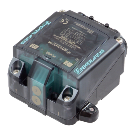
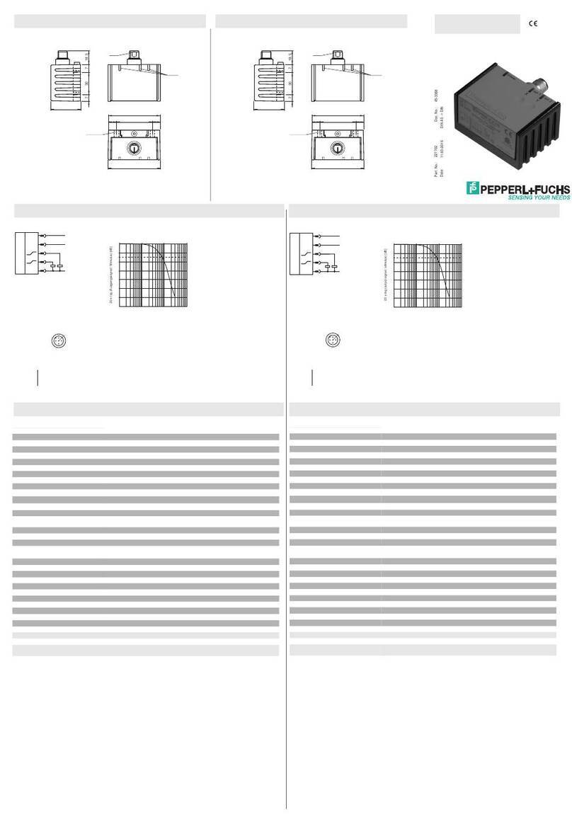
  9. Pepperl+Fuchs INX360D-F99-I2E2-V15 User manual

Pepperl+Fuchs INX360D-F99-I2E2-V15 User manual

Subject to reasonable modifications due to technical advances. Copyright Pepperl+Fuchs, Printed in Germany
Pepperl+Fuchs Group • Tel.: Germany +49 621 776-0 • USA +1 330 4253555 • Singapore +65 67799091 • Internet http://www.pepperl-fuchs.com
1
Inclination sensor INX360D-F99-I2E2-V15
Release date: 2011-08-17 14:11 Date of edition: 2011-08-17 201503_eng.xml
Model number
INX360D-F99-I2E2-V15
Features
• Measuring range 0 ... 360°
• Analog output 4 mA ... 20 mA
• Evaluation limits can be taught-in
• 2 programmable switch outputs
• High shock resistance
• e1-Type approval
• Increased noise immunity 100 V/m
EMC Properties
Emitted interference and interference immunity in accordance with motor vehicle directive 2006/28/EG (e1 Type approval)
Interference immunity in accordance with
DIN ISO 11452-2: 100 V/m
Frequency band 20 MHz up to 2 GHz
Mains-borne interference in accordance with ISO 7637-2:
Technical Data
General specifications
Type Inclination sensor, 1-axis
Measurement range 0 ... 360 °
Absolute accuracy ≤± 0.5 °
Response delay ≤20 ms
Resolution ≤0.1 °
Repeat accuracy ≤± 0.1 °
Temperature influence ≤0.027 °/K
Functional safety related parameters
MTTFd300 a
Mission Time (TM) 20 a
Diagnostic Coverage (DC) 0 %
Indicators/operating means
Operating display LED, green
TEACH-IN indication 2 LEDs yellow (switching status), flashing
Button 2 push-buttons ( Switch points programming , Evaluation
range programming )
Switching state 2 yellow LEDs: Switching status (each output)
Electrical specifications
Operating voltage UB10 ... 30 V DC
No-load supply current I0≤25 mA
Time delay before availability tv≤200 ms
Switching output
Output type 2 switch outputs PNP, NO , reverse polarity protected ,
short-circuit protected
Operating current IL≤100 mA
Voltage drop ≤3 V
Analog output
Output type 1 current output 4 ... 20 mA
Load resistor 0 ... 200 Ωat UB= 10 ... 18 V
0 ... 500 Ωat UB= 18 ... 30 V
Ambient conditions
Ambient temperature -40 ... 85 °C (-40 ... 185 °F)
Storage temperature -40 ... 85 °C (-40 ... 185 °F)
Mechanical specifications
Connection type M12 x 1 connector, 5-pin
Housing material PA
Protection degree IP68 / IP69K
Mass 240 g
Compliance with standards and
directives
Standard conformity
Shock and impact resistance 100 gaccording to DIN EN 60068-2-27
Standards EN 60947-5-2:2007
IEC 60947-5-2:2007
Approvals and certificates
CSA approval cCSAus Listed, General Purpose, Class 2 Power Source
CCC approval Products with a maximum operating voltage of ≤36 V do
not bear a CCC marking because they do not require
approval.
e1 Type approval 2006/28/EG
Pulse 1 2a 2b 3a 3b 4
Severity level III III III III III III
Failure criterion C A C A A C
EN 61000-4-2: CD: 8 kV / AD: 15 kV
Severity level IV IV
EN 61000-4-3: 30 V/m (80...2500 MHz)
Severity level IV
EN 61000-4-4: 2 kV
Severity level III
EN 61000-4-6: 10 V (0.01...80 MHz)
Severity level III
EN 55011: Klasse A
Subject to reasonable modifications due to technical advances. Copyright Pepperl+Fuchs, Printed in Germany
Pepperl+Fuchs Group • Tel.: Germany +49 621 776-0 • USA +1 330 4253555 • Singapore +65 67799091 • Internet http://www.pepperl-fuchs.com
Inclination sensor INX360D-F99-I2E2-V15
2
Release date: 2011-08-17 14:11 Date of edition: 2011-08-17 201503_eng.xml
Sensor Orientation
In the default setting the zero position of the sensor is reached, when the electrical connection faces straight upwards.
- On request, all required mounting positions can be preset at the factory.
For example: X = 0 if the electrical connection points straight downwards.
X Orientation
Mounting of the sensor
Inclination sensors from the -F99 series consist of a sensor module and accompanying cast aluminum housing. Select a flat surface
with minimum dimensions of 70 mm x 50 mm to mount the sensor.
Mount the sensor as follows:
1. Loosen the central screw under the sensor connection.
2. Slide back the clamping element until you are able to remove the sensor module from the housing.
3. Remove the sensor module from the housing
4. Position the housing at the required mounting location and secure using four countersunk screws. Make sure that the heads
of the screws do not protrude.
5. Place the sensor module in the housing.
6. Slide the clamping element flush into the housing. Check that the sensor element is seated correctly.
7. Finally tighten the central screw.
The inclination sensor is now mounted correctly.
LED display
Dimensions
Button
104510
64
65
4 x ø 5.5
M12
730 718.5
37
LEDs
+
-
X = 0° X = 90° X = ±180° X = 270° (-90°)
5.
7.
6.
4.
1.
2.
3.
Electrical connection
Pinout
Accessories
V15-G-2M-PUR
Cable socket, M12, 5-pin, PUR cable
V15-W-2M-PUR
Cable socket, M12, 5-pin, PUR cable
Standard symbol/Connection:
+U
B
Out 2
Out 1
Analogue output
-U
B
I
1
3
2
4
5
1
3
4
5
2
1 BN
2 WH
3 BU
4 BK
5 GY
Wire colors in accordance with EN 60947-5-2
(brown)
(white)
(blue)
(black)
(gray)
Subject to reasonable modifications due to technical advances. Copyright Pepperl+Fuchs, Printed in Germany
Pepperl+Fuchs Group • Tel.: Germany +49 621 776-0 • USA +1 330 4253555 • Singapore +65 67799091 • Internet http://www.pepperl-fuchs.com
Inclination sensor INX360D-F99-I2E2-V15
3
Release date: 2011-08-17 14:11 Date of edition: 2011-08-17 201503_eng.xml
Axis definition
The definition of the X-axis is shown on the sensor housing by means of an imprinted and labeled double arrow. The figure shows the clockwise direction of
rotation.
Teach-in of switching points (output S1)
1. Press key T1 > 2 s (see LED display)
2. Move sensor to switching position 1
3. Press key T1 briefly. LED "out 1" lights for 1.5 s as confirmation. Switching point 1 has been taught
4. Move sensor to switching position 2
5. Press key T1 briefly. LED "out 1" lights for 1.5 s as confirmation. Switching point 2 has been taught
6. Sensor returns to normal operation (see LED display)
If the switching points are taught in clockwise direction, the switching output between these switching points works as a NO contact. If the switching
points are taught in anticlockwise direction, the switching output between these switching points works as a NC contact.
Teach-in of switching points (output S2)
Similar to the process for "Teach-in of switching points (output S1)“, but with key T2 instead of key T1.
Teach-in of analog limits
1. Activate the teach-in mode for the analog limits by simultaneously pressing keys T1 and T2 until the green LED is extinguished and the two yellow LEDs flash. Then release the keys.
2. Press key T1 > for 2 s (see LED display)
3. Move the sensor into the position of minimum evaluation limit
4. Press key T1 briefly. LED "out 1" lights for 1.5 s as confirmation. The minimum evaluation limit has been taught. In this position the analog output will provide its minimum output value.
5. Move the sensor into the position of maximum evaluation limit
6. Press key T1 briefly. LED "out 1" lights for 1.5 s as confirmation. The maximum evaluation limit has been taught. In this position the analog output will provide its maximum output value.
7. Sensor returns to normal operation (see LED display)
If the sensor inclination exceeds one of the analog limits, the last value of the analog output is retained.
Resetting the sensor to factory settings
1. Press keys T1 and T2 > 10 s (see LED display)
2. The sensor has been reset when the green LED "Power" lights again after approx. 10 s.
Undervoltage detection
If the supply voltage falls below a value of approx. 7 V, all outputs and yellow LEDs are deactivated. The green "power" LED flashes rapidly. If the supply voltage falls below a value of approx. 8 V, the
sensor continues with normal operation.
Displays dependent on the operating state LED green:
Power
LED yellow
out 1
LED yellow
out 2
Teach-in of switching points (output S1):
Teach-in of switching points (output S2):
off
off
flashes
off
off
flashes
Activate teach-in mode for analog limits:
Teach-in of analog limits
off
off
flashes
flashes
flashes
off
Normal operation on switchingstate switchingstate
Reset to factory settings:
2 s ... 10 s
> 10 s ... end of reset process
Followed by normal operation
off
flashes
flashes
off
flashes
off
Undervoltage flashes off off
X

Other Pepperl+Fuchs Security Sensor manuals

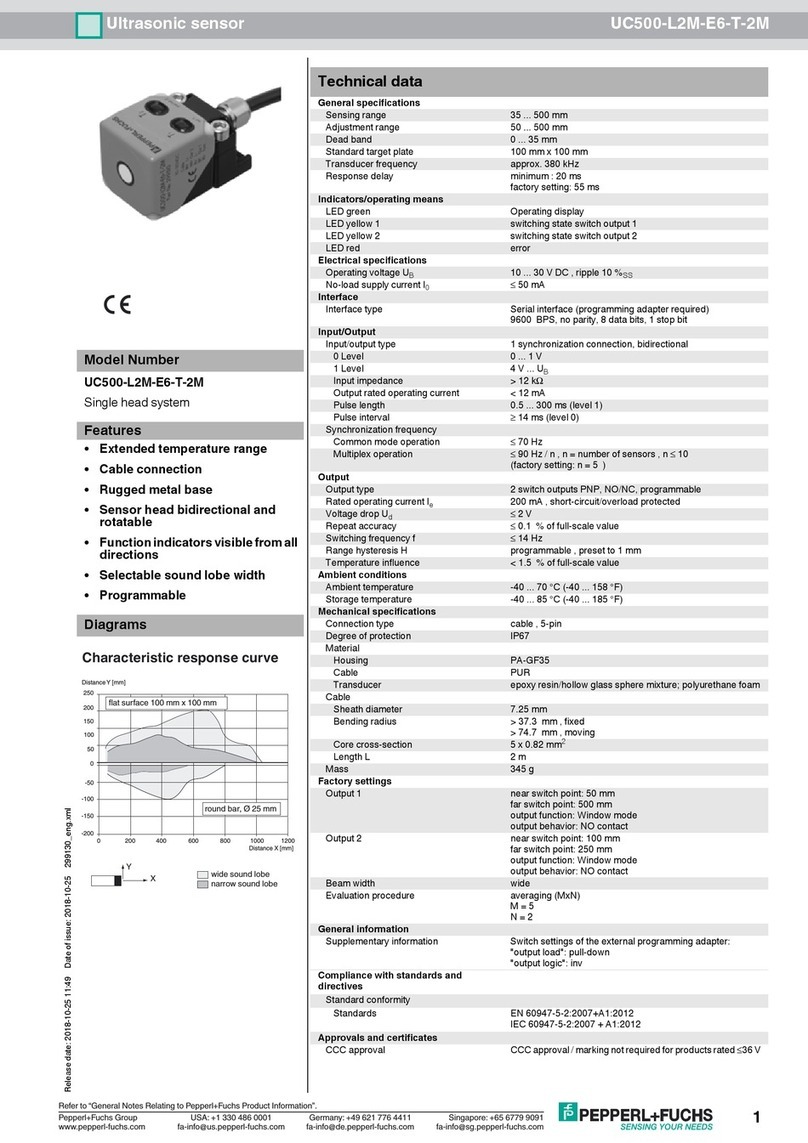
Pepperl+Fuchs UC500-L2M-E6-T-2M User manual

Pepperl+Fuchs

Pepperl+Fuchs UC500-L2M-E6-T-2M User manual

Pepperl+Fuchs NBB2-12GS40-Z4L-V1-3G-3D User manual

Pepperl+Fuchs

Pepperl+Fuchs NBB2-12GS40-Z4L-V1-3G-3D User manual

Pepperl+Fuchs UC6000-30GM-IUEP-IO-V15 User manual

Pepperl+Fuchs

Pepperl+Fuchs UC6000-30GM-IUEP-IO-V15 User manual

Pepperl+Fuchs UC2000-30GM-IUEP-IO-V15 User manual

Pepperl+Fuchs

Pepperl+Fuchs UC2000-30GM-IUEP-IO-V15 User manual

Pepperl+Fuchs NBB15-30GM50-E3-V1-3G-3D User manual

Pepperl+Fuchs

Pepperl+Fuchs NBB15-30GM50-E3-V1-3G-3D User manual

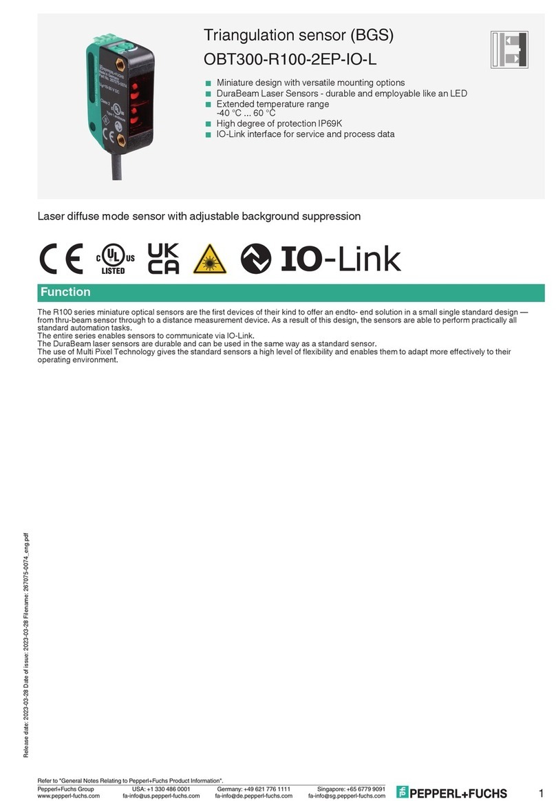
Pepperl+Fuchs OBT300-R100-2EP-IO-L User manual

Pepperl+Fuchs

Pepperl+Fuchs OBT300-R100-2EP-IO-L User manual

Pepperl+Fuchs UC2000-L2-E5-V15-Y291515 User manual

Pepperl+Fuchs

Pepperl+Fuchs UC2000-L2-E5-V15-Y291515 User manual

Pepperl+Fuchs NCN3-F31K2 Series User manual

Pepperl+Fuchs

Pepperl+Fuchs NCN3-F31K2 Series User manual

Pepperl+Fuchs RL28-55-LAS-B3B/73c User manual

Pepperl+Fuchs

Pepperl+Fuchs RL28-55-LAS-B3B/73c User manual

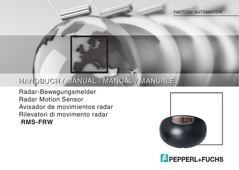
Pepperl+Fuchs RMS-FRW User manual

Pepperl+Fuchs

Pepperl+Fuchs RMS-FRW User manual

Pepperl+Fuchs CCB10-30GS55-N1-V1 User manual

Pepperl+Fuchs

Pepperl+Fuchs CCB10-30GS55-N1-V1 User manual

Pepperl+Fuchs NBB15-30GM50-E2-V1-3G-3D User manual

Pepperl+Fuchs

Pepperl+Fuchs NBB15-30GM50-E2-V1-3G-3D User manual

Pepperl+Fuchs KFD2-ELD-Ex16 User manual

Pepperl+Fuchs

Pepperl+Fuchs KFD2-ELD-Ex16 User manual

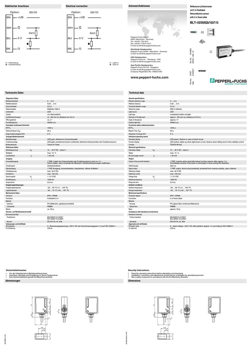
Pepperl+Fuchs ML71-55 User manual

Pepperl+Fuchs

Pepperl+Fuchs ML71-55 User manual

Pepperl+Fuchs NBB5-18GS50-Z4L-V1-3G-3D User manual

Pepperl+Fuchs

Pepperl+Fuchs NBB5-18GS50-Z4L-V1-3G-3D User manual

Pepperl+Fuchs NBN15-30GS50-Z4L-V1-3G-3D User manual

Pepperl+Fuchs

Pepperl+Fuchs NBN15-30GS50-Z4L-V1-3G-3D User manual

Pepperl+Fuchs SLCT Series User manual

Pepperl+Fuchs

Pepperl+Fuchs SLCT Series User manual

Pepperl+Fuchs DoorScan User manual

Pepperl+Fuchs

Pepperl+Fuchs DoorScan User manual

Pepperl+Fuchs LC10 Series User manual

Pepperl+Fuchs

Pepperl+Fuchs LC10 Series User manual

Pepperl+Fuchs GLP30-RT/40b/103/123/143 User manual

Pepperl+Fuchs

Pepperl+Fuchs GLP30-RT/40b/103/123/143 User manual

Pepperl+Fuchs VAS/M-2A8L-KE4-6SE-EV User manual

Pepperl+Fuchs

Pepperl+Fuchs VAS/M-2A8L-KE4-6SE-EV User manual

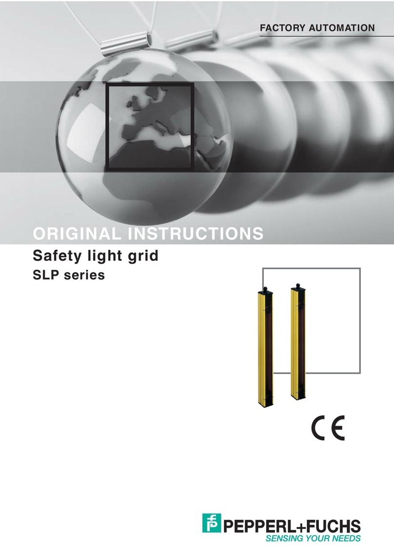
Pepperl+Fuchs SLP Series User manual

Pepperl+Fuchs

Pepperl+Fuchs SLP Series User manual

Pepperl+Fuchs UC2000-30GM-IUEP-IO-V15-Y User manual

Pepperl+Fuchs

Pepperl+Fuchs UC2000-30GM-IUEP-IO-V15-Y User manual

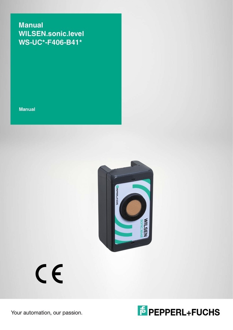
Pepperl+Fuchs WILSEN.sonic.level WS-UCC4000 User manual

Pepperl+Fuchs

Pepperl+Fuchs WILSEN.sonic.level WS-UCC4000 User manual

Popular Security Sensor manuals by other brands

Aritech RF430I4 Installation sheet

Aritech

Aritech RF430I4 Installation sheet

urmet domus 1083 manual

urmet domus

urmet domus 1083 manual

Visonic MCT-302 quick start guide

Visonic

Visonic MCT-302 quick start guide

Crewsaver CREWFIT 165 SPORT owner's manual

Crewsaver

Crewsaver CREWFIT 165 SPORT owner's manual

Southwest Microwave 310B Technical manual

Southwest Microwave

Southwest Microwave 310B Technical manual

Amprobe ULD-405 user manual

Amprobe

Amprobe ULD-405 user manual

AVS Electronics BM60HP manual

AVS Electronics

AVS Electronics BM60HP manual

Argus Security Taurus TW-DT-01/916 manual

Argus Security

Argus Security Taurus TW-DT-01/916 manual

Respirex GLS 300 A User instructions

Respirex

Respirex GLS 300 A User instructions

B.E.G. LUXOMAT PD4-S-K manual

B.E.G.

B.E.G. LUXOMAT PD4-S-K manual

Essence Care@Home Hip Fall Detector user guide

Essence

Essence Care@Home Hip Fall Detector user guide

EINHELL TC-MD 50 Original operating instructions

EINHELL

EINHELL TC-MD 50 Original operating instructions

Korno GT-1000 SERIES user manual

Korno

Korno GT-1000 SERIES user manual

Smartwares SH5-TSM-A quick start guide

Smartwares

Smartwares SH5-TSM-A quick start guide

Varian 959D Operation manual

Varian

Varian 959D Operation manual

Surface Concept Delayline DLD 8080 manual

Surface Concept

Surface Concept Delayline DLD 8080 manual

Tyco Visonic SD-304C PG2 installation instructions

Tyco

Tyco Visonic SD-304C PG2 installation instructions

DELTA DORE TYXAL DU installation guide

DELTA DORE

DELTA DORE TYXAL DU installation guide

manuals.online logo
manuals.online logoBrands
  • About & Mission
  • Contact us
  • Privacy Policy
  • Terms and Conditions

Copyright 2025 Manuals.Online. All Rights Reserved.