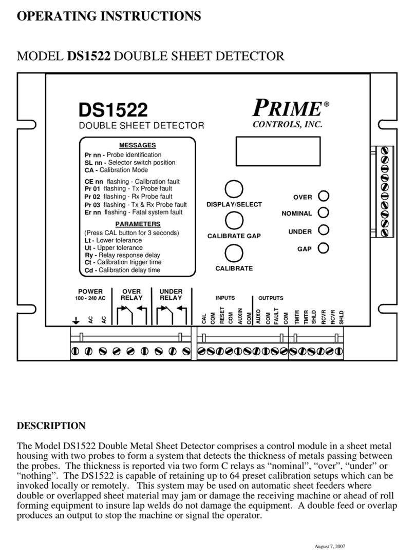
is removed from the DS3410. Depending upon selected options, the system can retain one,
four, or up to 8 different calibration settings in non-volatile memory. See the separate section
on MULTIPLE CALIBRATION MEMORIES. To calibrate on single and double, proceed as
follows:
1. Set the memory select inputs (SEL1 and SEL2 and optionally ENABLE) to select the
desired calibration memory.
2. Place a single sheet of the thickness to be gauged in the probe gap and press the CAL push
button or close a contact across the external CAL input. The unit displays “CA” and flashes
the LEDs sequentially. If the calibration on single is accepted, the unit displays alternately
"CA" and "2" indicating readiness to calibrate on a double thickness.
If the calibration is not successful, the unit displays alternately "CE" and “01” if the signal is
too weak or “CE” and “02” if the signal is too strong. Calibration may be attempted again
immediately. If calibration is not re-attempted, after 30 seconds the unit reverts to the state
prior to the attempted calibration.
3. Place a double thickness of material to be gauged in the probe gap and press the CAL push
button or close a contact across the external CAL input. When calibration is complete the
signal strength value returns to the display.
4. Adjust the gauge tolerance values if necessary (See Gauge Tolerance Adjustment under
INITIAL SETUP) and proceed with normal operation.
Calibration on Single Thickness
Switch 1 OFF, selects calibration on single thickness. For proper operation, the double sheet
detector must be calibrated any time prior to running or, optionally, the unit may calibrate on
the first board or sheet of a run. Calibration values are retained when power is removed from
the DS3410. Up to four (optionally eight, depending upon switch 2 setting) different
calibration settings may be retained in the calibration memories as determined by the signals on
the SEL1 and SEL2 (and optionally ENABLE) inputs.
1. Set the memory select inputs (SEL1 and SEL2 and optionally ENABLE) to select the
desired calibration memory.
2. Enter the "Calibrate" mode by momentarily closing a contact across the CAL and COM
terminals or pressing the push-button switch on the front of the DS3410 control module.
The unit displays “CA” and flashes the LEDs sequentially as it calibrates or as it waits for
material to come between the probes. The external contact may remain closed as the single
sheet feeds through the probe gap, but must be opened before a second sheet is fed.
3. Pass a single sheet of the thickness to be gauged through the probe gap. The sheet may be
inserted in the gap before initiation of the calibrate mode, but must be in the gap for at least
duration of the calibration delay (“Ct”) for proper calibration. The intent of the calibration
delay is to insure that a slow-moving calibration target is fully between the probes when
calibration begins.
Gauging commences immediately after calibration but only if the push button is released and
the contact across CAL and COM is released. If either of the calibration initiating signals
persists, the unit hangs in a wait state.


