ARAG BRAVO 300S Quick start guide

300S Bravo SerieS computer
muLti-roW SpraYer
• DIRECT CONNECTION: 46731XXX
• RCU: 46733XXX
Software rel. 3.1x
INSTALLATION, uSe ANd mAINTeNANce

2
=Generic danger
=Warning
LEGEND OF SYMBOLS
This manual is an integral part of the equipment to which it refers and must accompany the equipment in case of sale
or change of ownership. Keep it for any future reference; ARAG reserves the right to modify product specications and
instructions at any moment and without notice.

3
CONTINUES
• Manualforewordanduse ................................................................................................................................................. 5
• Manualusemodes ............................................................................................................................................................ 5
• Limitations ......................................................................................................................................................................... 5
• Responsibility.................................................................................................................................................................... 5
1 Risksandprotectionsbeforeassembly.......................................................................................................................... 6
2 BravoDSB.......................................................................................................................................................................... 6
3 Intendeduse ...................................................................................................................................................................... 6
4 Precautions ........................................................................................................................................................................ 6
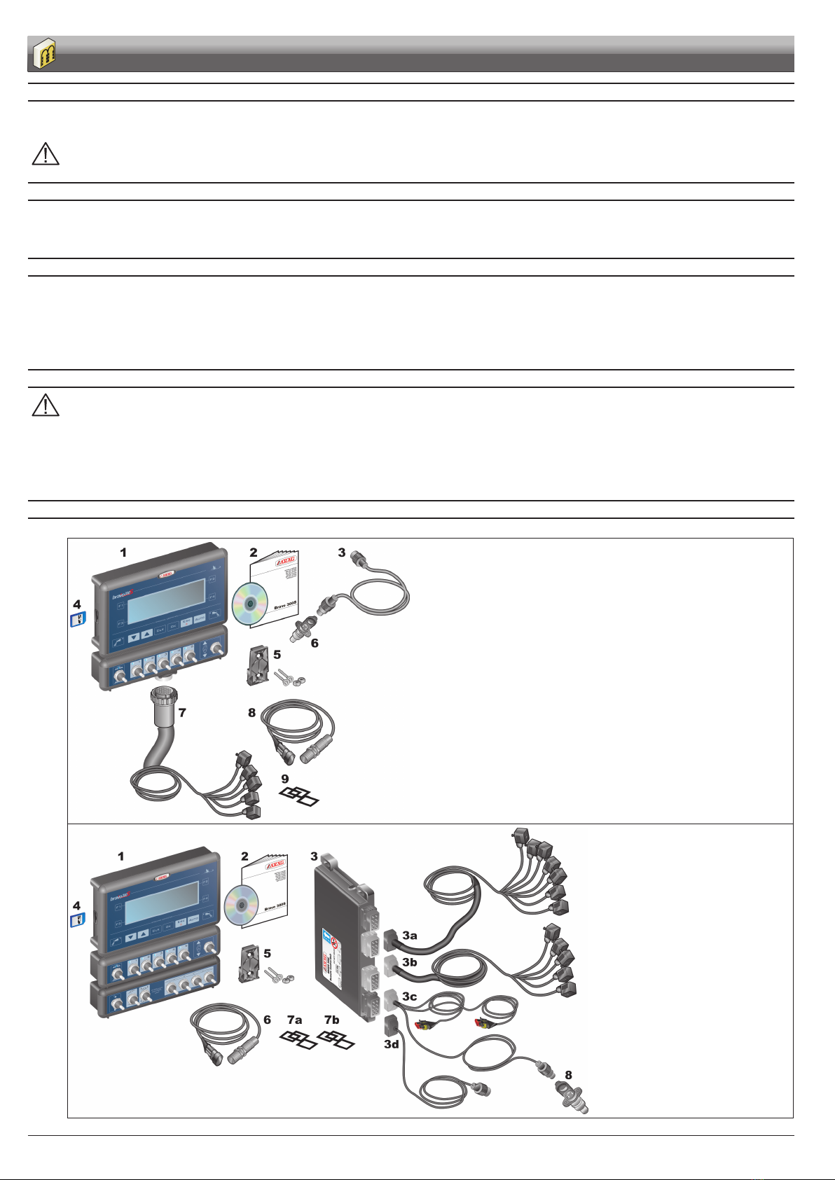
5 Packagecontent ................................................................................................................................................................ 6
6 Positiononfarmingmachine ........................................................................................................................................... 7
6.1 System recommended composition ........................................................................................................................... 7
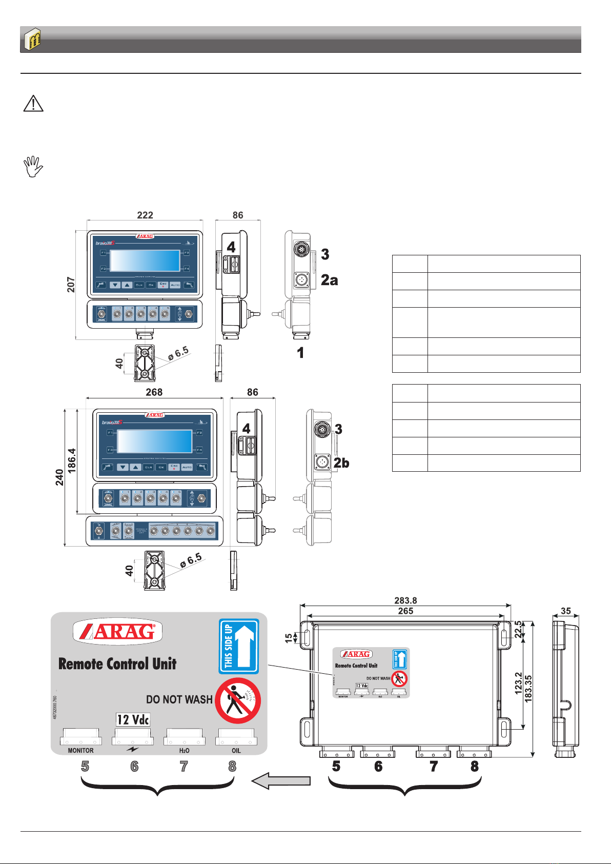
6.2 Monitor and control unit positioning...........................................................................................................................10
6.3 Bracket fixing.............................................................................................................................................................11
6.4 Control unit (RCU) fixing ...........................................................................................................................................11
6.5 Control unit position...................................................................................................................................................11
7 Computerconnectiontothefarmingmachine............................................................................................................. 12
7.1 General precautions for a correct harness position.................................................................................................. 12
7.2 Power supply connection.......................................................................................................................................... 13
8 Harnessconnectiontothecontrolunit,thehydraulicunitandtheavailablefunctions .......................................... 14
8.1 Multicore connector connection (FOR VERSIONS WITH DIRECT CONNECTION ONLY) ..................................... 14
8.2 Remote control unit (RCU) connection..................................................................................................................... 14
8.3 Control unit valve connection ................................................................................................................................... 14
8.4 Hydraulic valves connection ..................................................................................................................................... 15
8.5 Connection of sensors and other available functions .............................................................................................. 16
8.6 SD memory card ...................................................................................................................................................... 17
9 Setup................................................................................................................................................................................. 18
9.1 Tests and checks before programming..................................................................................................................... 18
9.2 Computer switching On/Off ...................................................................................................................................... 18
9.3 Use of keys for programming.................................................................................................................................... 19
10Advancedsetup............................................................................................................................................................... 20
10.1 Language ................................................................................................................................................................. 21
10.2 Unit of measurement................................................................................................................................................ 21
10.3 Section valves number ............................................................................................................................................. 21
10.4 Coverage.................................................................................................................................................................. 21
10.8 Valves....................................................................................................................................................................... 22
10.5 Flowmeter................................................................................................................................................................. 23
10.6 Pressure sensor ....................................................................................................................................................... 23
10.7 Delivery cal. sensor .................................................................................................................................................. 23
10.9 Tank level ................................................................................................................................................................. 24
10.9.1 Tank level - Manual Mode ...................................................................................................................................... 24
10.9.2 Tank level - Filling flowmeter mode ........................................................................................................................ 24
10.9.3 Tank level - Level sensor mode .............................................................................................................................. 25
10.10 Rev counter ............................................................................................................................................................. 26
10.11 Foam marker ........................................................................................................................................................... 26
10.12 Pump Protector........................................................................................................................................................ 26
10.13 Configuration check after Advanced setup end ....................................................................................................... 27
CONTENTS

4
11 Usersetting...................................................................................................................................................................... 28
11.1 Speed....................................................................................................................................................................... 29
11.1.1 Source - Wheel sensor............................................................................................................................................. 29
11.1.2 Source - GPS........................................................................................................................................................... 29
11.2 Jobs setup................................................................................................................................................................ 30
11.3 Nozzles setup........................................................................................................................................................... 31
11.4 Booms setup ............................................................................................................................................................ 31
11.5 Working limits ........................................................................................................................................................... 32
11.6 Flowrate correct. factor ............................................................................................................................................. 32
11.7 User preferences...................................................................................................................................................... 32
11.8 Date and Time .......................................................................................................................................................... 33
11.9 Data logger............................................................................................................................................................... 33
11.10 Test........................................................................................................................................................................... 34
11.11 Load/save setup ....................................................................................................................................................... 36
11.12 Totalizers .................................................................................................................................................................. 37
12Jobfunctions................................................................................................................................................................... 38
12.1 F1 - Job selection(PAGE 1)..................................................................................................................................... 39
12.2 F2 - Current job data(PAGE 1)................................................................................................................................ 40
12.3 F3 - Zero transducer setup(PAGE 1)....................................................................................................................... 40
12.4 F4 - Tank(PAGE 1) .................................................................................................................................................. 41
12.5 F4 - Tank(PAGE 1) .................................................................................................................................................. 42
12.6 F4 - User setting(PAGE 2)....................................................................................................................................... 42
13Use.................................................................................................................................................................................... 43
13.1 Controls on computer ............................................................................................................................................... 43
13.2 Control, selection or modification keys ..................................................................................................................... 44
13.3 Operating switches for control unit valves ................................................................................................................ 44
13.4 Operating switches for hydraulic valves.................................................................................................................... 44
13.5 Display...................................................................................................................................................................... 44
13.6 Treatment preliminary settings ................................................................................................................................. 44
13.7 Output rate regulation............................................................................................................................................... 45
13.7.1Automatic operation (DEFAULT)............................................................................................................................... 45
13.7.2Manual operation ..................................................................................................................................................... 45
13.8 Section valves automatic switch-off (through SKIPPER).......................................................................................... 45
14Maintenance/diagnostics/repairs............................................................................................................................... 46
14.1 Operation errors ....................................................................................................................................................... 46
14.2 Troubleshooting ........................................................................................................................................................ 47
14.3 Cleaning rules .......................................................................................................................................................... 47
15Technicaldata.................................................................................................................................................................. 48
15.1 Computer technical data .......................................................................................................................................... 49
16Endoflifedisposal ......................................................................................................................................................... 50
17Guaranteeterms .............................................................................................................................................................. 50
CONTENTS

5
This manual provides instructions to assemble, connect and set the computers of the BRAVO 300S family.
Any other information is provided in specic sheets to be used exclusively by the installer, containing specic information of each computer model.
The section of this manual dedicated to the installation contains information for installers. For this reason we have used technical terms without
providing explanations which would be necessary for end users only.
THEINSTALLATIONMUSTBECARRIEDOUTBYAUTHORISEDANDSKILLEDPERSONNELONLY.THEMANUFACTURERIS
NOTRESPONSIBLEFORANYOPERATIONSPECIFIEDINTHISMANUALCARRIEDOUTBYUNAUTHORISEDORUNSKILLED
PERSONNEL.
The descriptions of the assembly phases refer to a “general” computer, so specic models will not be mentioned, unless a certain installation procedure
concerns exclusively one computer type.
The installer must carry out workmanlike installations and ensure to the end user the perfect operation of the whole system both with ARAG components
only and other brands' components.
ARAG always recommends using its components to install control systems.
The installer will be held responsible for any malfunction if he decides to use other brands' components even without actually changing the system
parts or harness.
The compatibility check with components and accessories of other manufacturers shall be carried out by the installer.
If the computer or the ARAG components installed together with other brands' components get damaged because of what stated above, no direct or
indirect warranty will be provided.
INTRODUCTION
Other manuals for BRAVO 300S
3
Table of contents
Other ARAG Paint Sprayer manuals