ARB RD203 User manual

ISUZU IFS, 17 SPLINE
AIR OPERATED
LOCKING DIFFERENTIAL
INSTALLATION GUIDE

No liability is assumed for damages resulting in the use of the information contained herein.
ARB Air Locker Locking Differentials and Air Locker are trademarks of ARB Corporation Limited.
Other product names used herein are for identification purposes only and may be trademarks of their respective owners.
ARB 4x4 ACCESSORIES
Corporate Head Office
42-44 Garden St Tel: +61 (3) 9761 6622
Kilsyth, Victoria Fax: +61 (3) 9761 6807
AUSTRALIA
3137
www.arb.com.au

1
1 Introduction 3
1.1 Pre-Installation Preparation 3
1.2 Tool-Kit Recommendations 4
2 Removing the Existing Differential 5
2.1 Vehicle Support 5
2.2 Differential Fluid Drain 5
2.3 Removal of the Axles and Differential 5
2.4 Marking the Bearing Caps 6
2.5 Checking the Current Backlash Amount 7
2.6 Spreading the Differential Housing 8
3 Bench Measurement 9
3.1 Measurement for Pre-Load Shimming 9
3.2 Calculation & Selection of Shims 11
4 Installing the Air Locker 12
4.1 Installing the Carrier Bearings 12
4.2 Mounting the Ring Gear 13
4.3 Drilling & Tapping the Bulkhead Port 14
4.4 Assembling the Differential Carrier 16
4.5 Modifying the Bearing Cap 18
4.6 Final Air Locker Assembly 19
4.7 Final Backlash Checking 20
4.8 Profiling the Seal Housing Tube 21
4.9 Setting up the Bulkhead Fitting 23
4.10 Bench Testing the Air Locker 24
4.11 Reinstalling the Axles 25
5 Installing the Air System 26
5.1 Mounting the Solenoid 26
5.2 Running & Securing the Air Line 28
5.3 Connection to the Bulkhead Fitting 29
6 Mounting & Connecting the Electrical System 30
6.1 Mounting the Actuator Switch(es) 30
6.2 Wiring the Actuator System 32
7 Testing & Final Assembly 35
7.1 Leak Testing 35
7.2 Testing the Air Locker Actuation 36
7.3 Filling the Differential 36
7.4 Post-Installation Check List 37
8 Parts List 39
8.1 Exploded Assembly Diagram 39
8.2 Itemized Parts List 40

2

1 Introduction
3
IMPORTANT :
BEFORE ATTEMPTING TO DISMANTLE YOUR VEHICLE FOR THIS
INSTALLATION, PLEASE READ THIS INSTALLATION GUIDE IN ITS
ENTIRETY, AS WELL AS ALL APPLICABLE SECTIONS OF YOUR
VEHICLE MANUFACTURER’S SERVICE MANUAL.
1.1 Pre-Installation Preparation
This booklet is to be used in conjunction with your vehicle
manufacturer’s service manual. ARB endeavors to account for every
possible variation in vehicle model when publishing its installation
guides, and guides are updated regularly as new model information
becomes available, however, the rapid and globally varied release of
some vehicles makes it difficult to insure that your vehicle model has
been accurately accounted for. In the case of any technical
discrepancies between this guide and your service manual, we
strongly advise that you adhere to the specifications and techniques
as documented in your service manual.
Although your ARB Air Locker comes complete with all the step by
step instructions you will need to supplement your vehicle
manufacturer’s service manual and install your new differential, ARB
recommends that you have your Air Locker installed by a trained
professional. Many ARB distributors around the world have been fully
instructed in Air Locker installations by ARB, and have gained a wealth
of experience and skill from years of performing similar installations.
Once you begin this installation your vehicle will be immobile until all
steps of the installation are complete. Make sure your Air Locker kit is
the correct model for your vehicle and that it contains all of the parts
listed on back cover of this booklet. Also be sure you have
appropriately equipped yourself with all the necessary tools, parts, and
materials to complete this installation (see section 1.2 Tool-Kit
Recommendations), and that you have allowed for an appropriate
amount of vehicle down time.
HINT : Place a mark inside each of the symbols as
you complete each step. It is very important NOT to
miss any of the steps!

1 Introduction
4
1.2 Tool-Kit Recommendations
Below is a list of tools and supplies you may need to complete this
installation. Requirements for your vehicle may vary. Please consult your
vehicle service manual for additional recommendations.
1.2.1 Tools
Standard automotive sizes (metric and/or imperial) of sockets,
wrenches, Allan keys, and drills.
A dial indicator or other suitable measuring tool for checking ring
& pinion backlash.
A standard automotive feeler gauge.
A razor knife to cut the nylon tubing.
A differential housing spreader, to facilitate removal of the carrier
(e.g. ARB Differential Spreader #0770003).
A torque wrench (See vehicle service manual for required torque
range.).
A lubricant drain reservoir.
Suitable measuring tools to measure a differential for pre-load
and/or backlash shimming (See Section 3 Bench Measurement).
An 11.2mm [7/16”] drill and ¼” NPT tap for bulkhead fitting
installation.
An automotive bearing puller (e.g. ARB Bearing Puller #0770001)
or a differential carrier bearing puller.
A bearing press or arbor press.
A suitable shim driver (e.g. ARB Shim Driver #0770004).
A soft hammer (e.g. raw hide or nylon).
1.2.2 Supplies
Thread lubricant/sealant compound (e.g., LOCTITE #567 Teflon
Paste).
Thread locking compound (e.g., LOCTITE #272).
A sufficient volume of differential oil to completely refill your
housing (see the ARB Air Locker Operating and Service Manual
for recommended lubricants).
A soap and water mixture to test for air leaks.

2 Removing the Existing Differential
5
2.1 Vehicle Support
Safely secure the vehicle on a hoist. We recommend supporting
the vehicle on a chassis hoist to keep the differential area at a
convenient working height and to leave the wheels and axles free
to be rotated and removed.
Once supported off the ground, release the parking brake and
leave the vehicle in neutral. Chock the wheels if necessary.
2.2 Differential Fluid Drain
Clean around the differential drain plug to prevent dirt from entering
the differential.
Position a fluid drain reservoir under the differential and loosen the
differential drain plug.
Completely drain all differential fluid.
Once drained, reinstall the drain plug finger tight to prevent drips
coming out of the housing and dust getting in.
HINT : This is a good time to check for metal particles in
your oil and in the bottom of the housing which may
indicate a worn bearing or differential component.
2.3 Removal of the Axles and Differential
Remove the front wheels from the vehicle.
Disconnect the drive shaft from the flange of the differential.
Remove the front axle assembly according to your vehicle
manufacturer service manual.
HINT : Remove the CV retaining clips on the hub assembly,
then separate the spindle/knuckle assembly to give way
to CV removal later. Do not attempt to pry the CV’s out
from the diff, as they are securely fastened to the
brackets with internal retaining clips. With the
differential housing properly supported, remove the 4
bolts on the bracket on each side, and then the 4 (or 2
in newer models) larger mounting bolts on the top.

2 Removing the Existing Differential
6
NOTE : Rubber oil seals can be easily damaged. Support the
weight of the axle when extracting it across the edges
of the seals.
Remove the differential housing from the axle case and secure it to
a workbench.
2.4 Marking the Bearing Caps
Using a pointed center punch, gently mark the bearing caps in a
way that will enable you to know which cap is ‘LEFT’ and which cap
is ‘RIGHT’, which way is ‘UP’ and which way is ‘DOWN’ (Fig.1.).
Mark the right hand cap in a similar way.
HINT : Many installers choose to make one punch mark on
the left hand side of the left hand bearing cap and one
similar punch mark on the housing at close proximity to
the cap mark. The right hand side is then designated
with two punch marks on the right hand side of the cap
and two similar punch marks on the housing.
Figure 1.

2 Removing the Existing Differential
7
2.5 Checking the Current Backlash Amount
IMPORTANT:
This step is a precautionary measure recommended by ARB due to
the fact that some aftermarket ring and pinion sets have been
manufactured to run with different backlash settings than those
specified by your vehicle manufacturer. Although ARB must
recommend you set backlash according to your service manual
guidelines, we also advise that you compare the backlash
measurements taken here to the recommended backlash settings in
your vehicle service manual. Measurements found to be outside of
your service manual recommendations may indicate the need to
deviate from those settings in order to achieve quiet running with a
good contact mark.
Refer to your vehicle service manual or your local authorized ARB
installer for more information.
Set a depth indicator on
one of the ring gear teeth
as in figure 2.
While supporting the pinion
gear by holding the drive
shaft, rotate the differential
in both directions while
observing the maximum
variation in depth from the
indicator (i.e., the highest
value minus the lowest
value). This value is
referred to as the ring and
pinion backlash.
Rotate the differential center 90and measure again for accuracy.
Record the average of all measurements.
Figure 2.

2 Removing the Existing Differential
8
2.6 Spreading the Differential Housing
IMPORTANT:
Spreading the differential housing with a differential case
spreader is a step which is critical to set up bearing pre-load
when a differential is installed. Improper pre-load will result in
undue bearing wear, increased stresses in the differential center,
increased running noise, and ultimately, ring and pinion gear
damage.
Unbolt and remove the bearing caps.
Setup the differential spreader and a dial indicator and carefully
spread the differential housing (Fig.3.) just enough to remove the
differential carrier (Refer to your vehicle’s service manual).
NOTE : Never spread the housing more than 0.5mm [0.020”].
Once the housing has been adequately spread, the differential may
be removed by pulling forward on the differential center.
Release all spreader tension immediately after removing the
differential carrier.
Figure 3.

3 Bench Measurement
9
3.1 Measurement for Pre-Load Shimming
When fitting an ARB Air Locker, the original bearing types are used on
both sides of the Air Locker, however, in order to reproduce a similar
backlash and pre-load to that of your existing differential,
measurements need to be taken so that the correct shim thickness
can be determined for each side.
Secure the differential to a workbench.
Remove the bolts that hold the ring gear
in place.
Using a plastic or copper hammer, tap in
a circle around the ring gear to separate
it from the differential carrier.
Remove the original tapered roller
bearings and shims from the differential
carrier using a bearing puller (Fig 4.).
NOTE : Keep the shims separated so
that they can be identified as
to which end of the
differential they came from.
HINT : Examine the bearing caps and cones for damage or
wear, and if necessary, discard them and replace with
the same size and type of bearings.
Figure 4.

3 Bench Measurement
10
Using a caliper or similarly accurate measurement method
(i.e., able to take accurate measurements within 0.04mm [0.0015”]),
measure the distance from the bearing shoulder to the ring gear
mounting face (shown as ‘A’ in Figure 5.) and record this
measurement as ‘A’.
Measure the thickness of the shim pack removed from the case
side of the differential carrier (shown as ‘B’ in Figure 5.) and record
this measurement as ‘B’.
Measure the distance from the Air Locker bearing shoulder to the
ring gear mounting face (shown as ‘C’ in Figure 6.) and record this
measurement as ‘C’.
Figure 5.

3 Bench Measurement
11
AIR LOCKER DIFFERENTIAL
Figure 6.
3.2 Calculation & Selection of Shims
The thickness of the shim pack required for the Air Locker (shown as
‘D’ in Figure 6.) can now be determined by substituting the
measurements taken into the following equation.
A + B – C = D
HINT : If your calculations are correct then the following
equation will also be true:
A + B – C – D = ZERO
To make a shim pack to match the measurement you calculated as ‘D’
you can:
select shims from the shim kit supplied with your Air Locker.
use a universal shim kit available from most drive train specialists.
NOTE : Never re-use any shims that are damaged or worn.
4 Installing the Air Locker
12
4.1 Installing the Carrier Bearings
With the Air Locker well supported in an arbor press, apply a thin
film of high-pressure grease to the case side bearing journal.
Identify the bearings according to where each was removed from
the OE diff, and allocate them to the correct sides of the Air Locker
respectively.
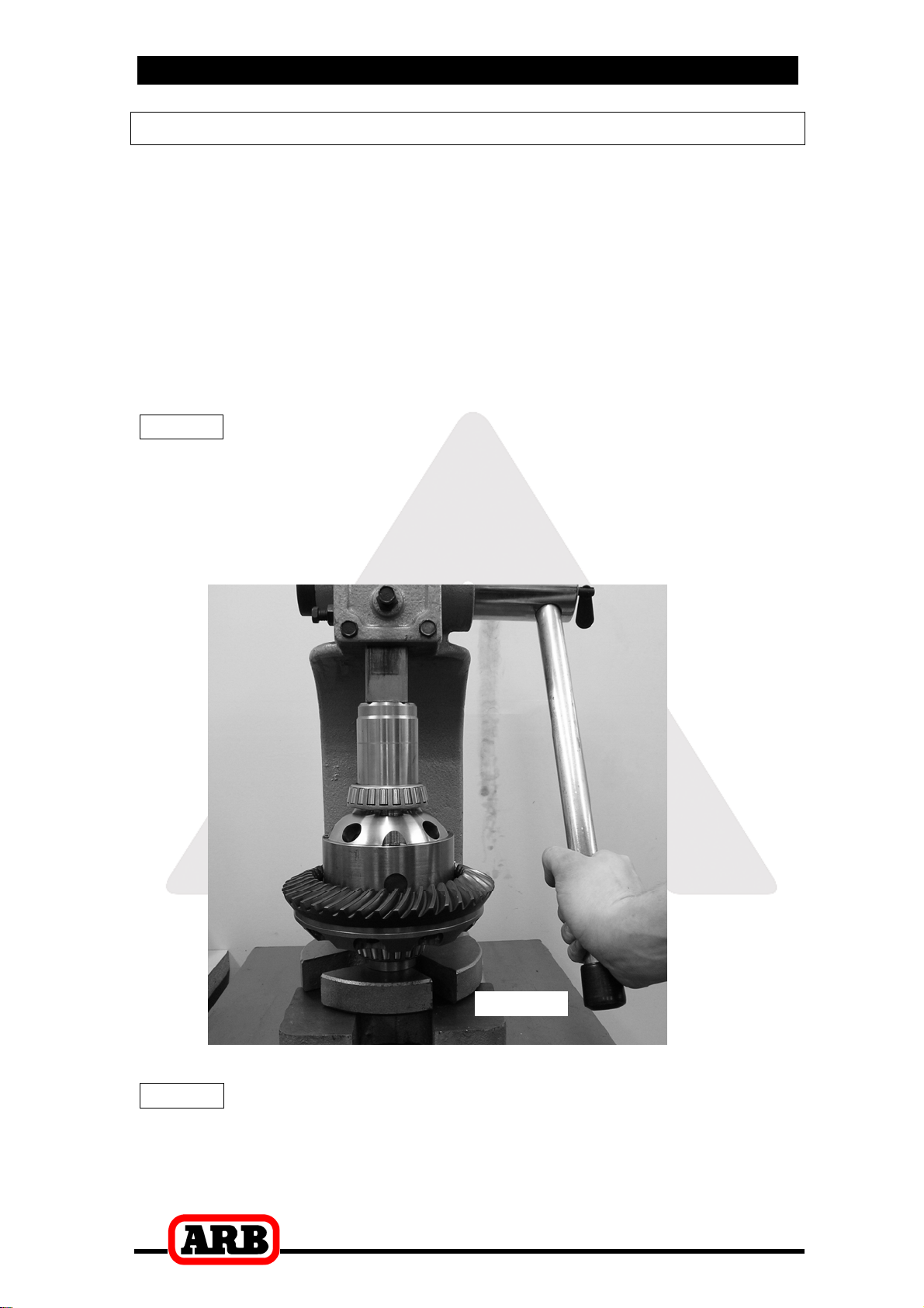
Press one of the tapered roller bearing cones onto the bearing
journal of the differential carrier until the bearing seats firmly
against the bearing journal shoulder. (Figure 7.)
NOTE : Never re-use any bearings that are damaged or worn.
Invert the Air Locker and apply a thin film of high-pressure grease
to the ring gear side bearing journal.
Press an original bearing cone onto the Air Locker bearing journal,
taking care not to damage the O-ring grooves.
Figure 7.
NOTE : Do not add any shims between the ring gear side
bearing and the bearing seat.

4 Installing the Air Locker
13
4.2 Mounting the Ring Gear
Apply a thin film of high-pressure grease to the ring gear shoulder
of the Air Locker to prevent seizing.
Thoroughly clean any thread locking compound or other foreign
matter from the holes of the ring gear, the threads of the ring gear
bolts, and the mating surfaces of the ring gear and the Air Locker
flange.
NOTE : Rubbing the ring gear mounting face with a flat oil
stone before installation will remove any high spots
around the threads.
Heat the ring gear to between 80 and 100C (175 - 212F) in an
oven or in hot water to slightly expand the gear and facilitate
assembly.
NOTE : NEVER HEAT GEARS WITH A FLAME! This could
damage the hardened surface of the gear and result in
premature wear or failure.
Dry the ring gear with compressed air (if wet), paying particular
attention to the threaded holes.
Install the ring gear onto the Air Locker by aligning the holes in the
flange with the tapped holes in the ring gear, then gently tapping it
around in a circle with a plastic or copper hammer.
NOTE : Avoid using the bolts to pull down the ring gear as
this puts excess strain on the bolts and the differential
flange.
Apply a thread-locking compound to the thread of each ring gear
bolt before inserting it.
NOTE : Do not apply threading compound directly into the
threaded hole as this could prevent the bolt from
reaching its full depth.
Tighten the ring gear bolts in a star pattern with a torque wrench
according to your vehicle manufacturer’s specified torque.

4 Installing the Air Locker
14
4.3 Drilling and Tapping the Bulkhead Port
A port must be drilled and tapped through the differential housing to
allow the seal housing tube through the housing to connect with the air
line from the air compressor.
IMPORTANT:
Some differentials on newer Isuzu models (e.g. 2012 DMax) are
assembled with aluminium axle case. Distinguish the material
type of the axle case, and then determine the bulkhead port
location as suggested below.
Cast Iron Axle Case.
Mark a spot for the bulkhead
port on the left hand (seal
housing) side toward the top of
the differential housing that is in
an area that will be well clear of
the ring gear, the differential,
and any other obstructions that
may snag the seal housing
tube (Fig.8.).
Aluminium Axle Case.
Mark a spot for the bulkhead port on the lower left corner (opposite
the oil fill plug) of the aluminium axle case, approximately
20~25mm from the centerline of the case. Ensure it is reasonably
distanced from the raised area (Fig. 9.), so that the bulkhead body
can be tightened in place later.
Figure 9.
HINT : The mark shown in figure 8. or 9. (either applicable)
should be copied as closely as possible.
Figure 8.
Leave clearance
from raised area.

4 Installing the Air Locker
15
Cover the drive pinion or axle tube areas with a rag to protect them
from metal filings.
Drill through the housing, square to the outside surface using an
11.2mm [7/16”] drill.
Tap the hole from the outside using a ¼’’ NPT tapered pipe thread
tap.
Remove any sharp edges from the hole that may chip-off and fall
into the housing.
Very carefully remove rags and inspect with a service light inside
the housing to ensure no metal filings are left behind.

4 Installing the Air Locker
16
AIR LOCKER DIFFERENTIAL
4.4 Assembling the Differential Carrier
Place the bearing cup over the bearing cone on the seal housing
side (Fig 10.)
Figure 10.
Carefully install the seal housing by sliding it all the way onto the
bearing journal with a gentle twisting motion until it sits flat against
the adjuster nut.
NOTE : A twisting motion (i.e., a slight rotation while pressing
the seal housing on) will allow the O-rings to engage
gently and prevent them from twisting. Twisted
O-rings will result in pre-mature O-ring wear and oil
contamination in the air system due to the helical
shape formed by the O-ring mould line.
By holding all assembled components as shown in Figure 10. In
place at each end (except the shim pack), insert and hold the Air
Locker into the differential housing with the seal housing tube
pointing straight out of the housing.

4 Installing the Air Locker
17
Push the Air Locker hard across to the case side, and measure the
gap (end float) between the seal housing and the bearing bore
edge with a feeler gauge.
Consult your vehicle manufacturer’s service manual to determine
the carrier bearing pre-load amount specified for your vehicle.
Add the specified pre-load amount to the measurement taken with
the feeler gauge to determine a shim amount for ‘E’ in Figure 10.
PRE-LOAD + END FLOAT = SHIM PACK
Select suitable shims from the supplied shim kit to make up a
shim pack of this thickness.

4 Installing the Air Locker
18
4.5 Modifying the Bearing Cap
NOTE : It is very important to make sure the punch marks
made on the differential housing while removing the
differential are matched to the punch marks on the
bearing cap. The bearing cap must be replaced
exactly as it was removed. (Refer to section 2.4)
Identify the bearing cap for the seal housing side. A hole must be
drilled in this cap for the seal housing tube to pass through.
Measure and mark a location on the bearing cap, off center as
shown, that would allow a 6.35mm [¼’’] hole to be drilled with 1mm
[0.039”] clearance from the edge of the hole and the machined
bearing recess. (Fig.11.)
Figure 11.
NOTE : Take time and double check when taking your
measurements, as bearing caps are custom fitted to
the diff housing and cannot be replaced.
Hold the bearing cap steady for drilling in a soft jawed vice clamp.
NOTE : Do not apply too much clamping pressure with the
vice. The bearing cap may be damaged.
Using a pedestal drill, drill a 6.35mm [¼’’] hole through the bearing
cap where the position has been marked.
Debur both ends of the drilled hole to remove any sharp edges.
1mm
Max
Table of contents
Popular Lock manuals by other brands


BOERBOEL
BOERBOEL Contemporary Post Latch with Handle installation instructions

Burg
Burg sPinLock 410 operating manual

Esco
Esco systeQ-4687 installation instructions

Coopers of Stortford
Coopers of Stortford G857 Instructions for use

Securam
Securam SafeLogic Basic operating instructions

Alarm Lock
Alarm Lock Trilogy DL1200 Mounting and installation instructions


