Roger ADL-2 User manual

ADL-2 Operating Manual Rev. D.docx 2023-10-18
Page 1of 15
DESIGN AND APPLICATION
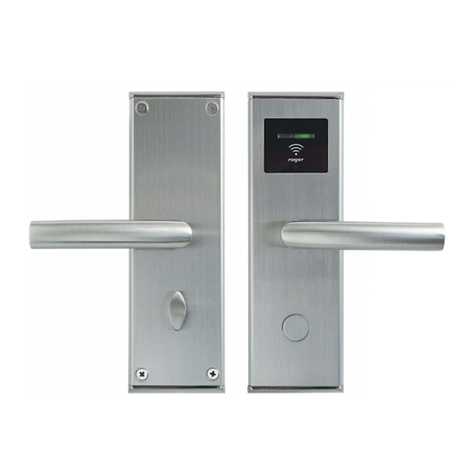
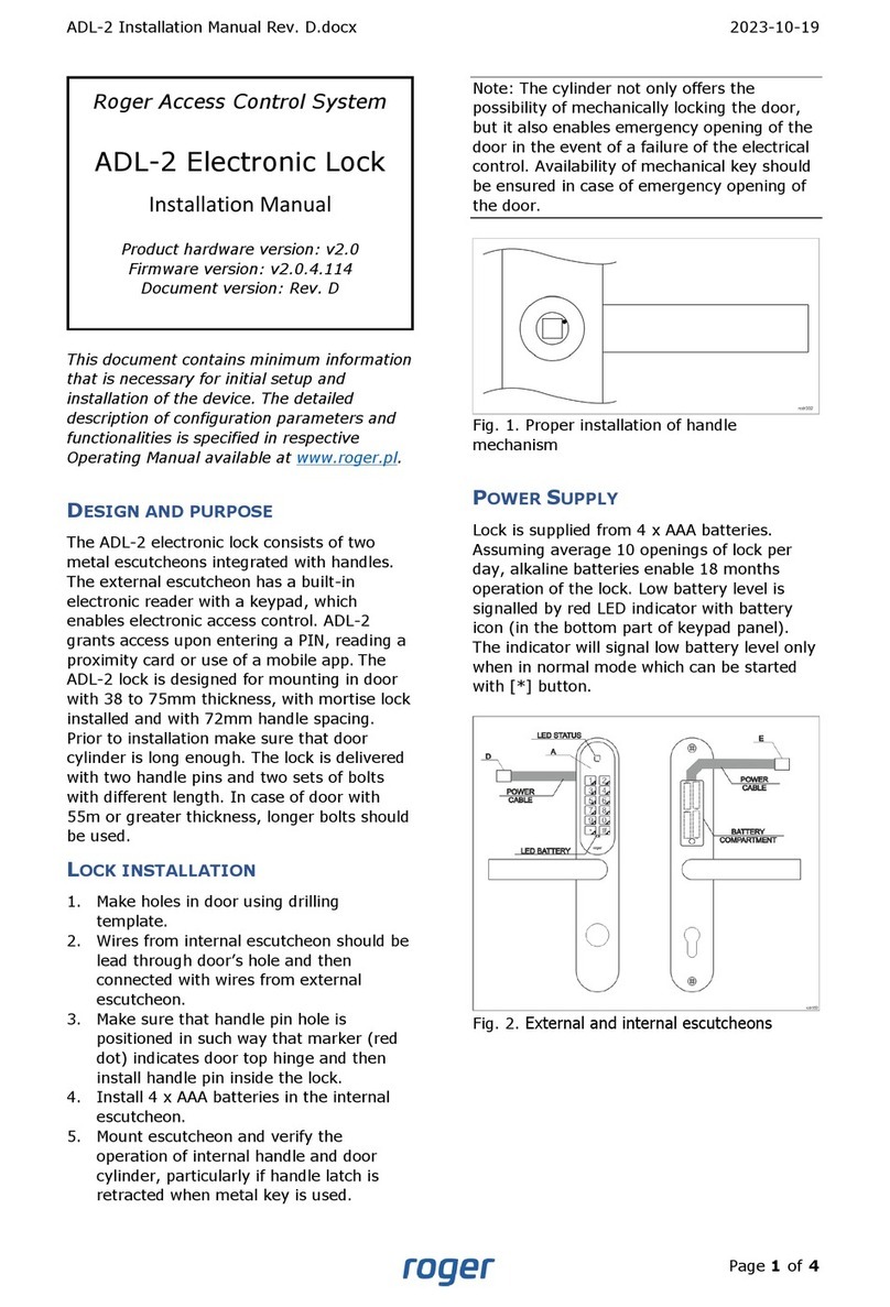
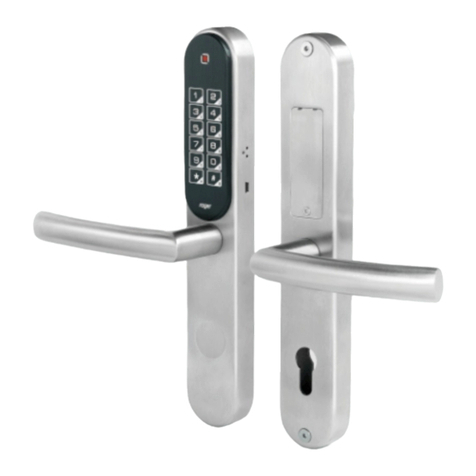
The ADL-2 electronic lock consists of two metal escutcheons integrated with handles. The external
escutcheon has a built-in electronic reader with a keypad, which enables electronic access control.
ADL-2 grants access upon entering a PIN code, reading a proximity card or use of a mobile app.
Access codes can be generated remotely at rps.roger.pl or programmed in the lock's internal memory
during its configuration. Remotely generated access codes may have a validity period. The lock is
operated using the Roger MDM mobile app, which, in addition to lock's configuration, enables reading
of an event log saved in the lock's memory and programming of the proximity access cards. ADL-2
lock can be installed on the most doors while retaining the existing internal mortise lock and cylinder.
The lock’s cylinder can be used for mechanical door locking or emergency door opening. Thanks to
the remotely generated codes, the lock is particularly suitable for short-term rental apartments. For
integration purposes, an SDK is available that allows you to generate remote PIN codes from third-
party systems.
CHARACTERISTICS
•PIN codes generated remotely in the Internet
•Email notification about newly created codes
•Validity period for remotely generated codes
•Access via PIN, proximity card or mobile app
•20 access codes programmed in the lock's memory
•One-time use and other special codes
•Event log
•Office Mode (door temporary open)
•PIN Blacklist
•Mechanical locking and emergency opening with a traditional door key
•Powered by four AAA batteries
•Emergency power supply socket
•Typical working life of 18 months with 10 openings per day
•Brushed stainless steel lock body
•Front escutcheon dimensions (WHD): 46x280x27mm
•Rear escutcheon dimensions (WHD): 46x280x20mm
•Mounting with two 5x50mm screw
•Lock spacing (handle-cylinder distance): 72mm
•Door thickness: 38 to 75mm
•SDK for generating PIN codes
•IK07
•IP20
•CE; RoHS
LOCK VERSIONS
Depending on door opening direction and handle location on the door leaf, the adequate type of ADL-
2 lock must be applied.
Roger Access Control System
ADL-2 Electronic Lock
Operating Manual
Product hardware version: v2.0
Firmware version: v2.0.4.114
Document version: Rev. D

ADL-2 Operating Manual Rev. D.docx 2023-10-18
Page 2of 15
Version
Description
ADL-2-L
Left hand doors
ADL-2-R
Right hand doors
Fig. 1. Door types for ADL-2-L lock
Fig. 2. Door types for ADL-2-R lock
MECHANICAL CONSTRUCTION
The lock consists of an external escutcheon equipped with a touch keypad panel and intended to be
mounted on the room entrance and an internal escutcheon containing a battery compartment and
mounted on the room exit.
External escutcheon
An electronic reader (A) with a touch keypad is in the external escutcheon. In the electronic module
located in the escutcheon, there are service contacts (B) and a connector (C) for connecting the
service cable. A bundle of wires terminated with a plug (D) comes out of the electronic module, which
is used to connect to the internal escutcheon. The handle on this escutcheon is free and becomes
temporarily engaged when access is granted or remains permanently engaged when the lock is in
Office Mode.

ADL-2 Operating Manual Rev. D.docx 2023-10-18
Page 3of 15
Fig. 3. External and internal escutcheons
Fig. 4. Electronic module inside the escutcheon
Internal escutcheon
Internal escutcheon includes battery pack. A bundle of wires terminated with a socket (E) comes out
of the battery pack. This socket should be connected to the matching plug (D) coming out of the
electronic module in the external escutcheon. To replace the battery, unscrew the cover. The handle
in this escutcheon is permanently mechanically engaged and allows you to leave the room regardless
of the electronic module.

ADL-2 Operating Manual Rev. D.docx 2023-10-18
Page 4of 15
Door cylinder
ADL-2 escutcheons can be fitted with a standard cylinder lock. This cylinder enables mechanical
locking of the door with a traditional mechanical key and can also be used for emergency opening of
the door in case of ADL-2 failure. The size of the cylinder depends on door thickness, and it must be
selected in such way that it would not protrude more than 16mm above door surface from the outside
and within the range of 21-24mm from the inside. It is possible to use cylinder lock with knob.
FUNCTIONAL DESCRIPTION
Typically, the handle in the external escutcheon is free and does not allow to open the door. Access
to the room is granted after entering correct PIN. PINs can be generated remotely (on the rps.roger.pl
website) or locally by saving them in the lock's internal memory. Start entering the PIN by pressing
the '*' key and finish it with the '#' key.
E.g.: *24376253#, *5470235093276#.
Note: Normally, the lock is in sleep mode. The lock wakes up when the '*' key is pressed. After
waking up, the lock generates a short acoustic signal and lights up the LED indicator. After 30
seconds of inactivity, the lock automatically enters sleep mode.
Access to the room can also be granted by means of proximity card with a valid PIN saved on it, or
from the level of the mobile app (RMK or Roger MDM). The PIN is saved on the card using Roger
MDM app. The ADL-2 lock supports only MFC-8 (Roger) proximity cards.
The ADL-2 lock supports so-called Office Mode. When Office Mode is enabled, then lock is
permanently unlocked (external handle is engaged) and it is not required to use access PIN for door
opening.
It is possible to deactivate selected PIN by entering it on the list of blocked codes (Blacklist). PIN
blocking can be achieved by using the PIN Master or from the Roger MDM app.
Depending on lock configuration, using the wrong PIN several times may temporarily block the lock.
The lock can also be blocked by using the PIN Block.
Remote PINs
Remote PINs are generated on http://rps.roger.pl website and they do not require lock programming.
PIN type
Description
PIN Guest 8
8-digit PIN. This PIN is valid for the selected number of days specified at the
time of its generation. PIN validity period is defined with an accuracy of 1 day
and limited to 365 days. PIN Guest can be blocked at any moment in the lock’s
configuration. Once the new PIN Guest is used the previous one is disabled.
PIN Guest 12
12-digit PIN. This PIN includes the start and end dates of its validity. When the
validity period is shorter than 42 days, it is defined with an accuracy of 1 hour. If
the validity period covers a period of more than 42 days, it is defined with an
accuracy of 1 day. Once the new PIN Guest is used the previous one is disabled.
PIN Single
12-digit PIN. This PIN is valid for the selected number of days specified at the
time of its generation. The validity period is defined with an accuracy of 1 day
and limited to 365 days. Once the PIN Single is used it is automatically disabled.
PIN Single allows single-time door access only.
PIN Office
12-digit PIN. This PIN has only the end of the validity period defined with an
accuracy of 1 day. This PIN allows you to alternately enable and disable the
Office Mode. Alternatively, Office Mode can be ended using a PIN Block.
PIN Block
12-digit PIN. This PIN allows to alternately block and unblock door access. PIN
Block has only the end of the validity period set with accuracy of 1 day. PIN
Block does not disable neither PIN Office nor PIN Master.

ADL-2 Operating Manual Rev. D.docx 2023-10-18
Page 5of 15
PIN Service
12-digit PIN. This PIN allows to enter the room and is intended for facility service
personnel. PIN Service has only the end of the validity period defined with an
accuracy of 1 day.
PIN Master
12-digit PIN. This PIN allows unconditional door entry despite the blocking state
caused by using the PIN Block. In addition, PIN Master allows adding the given
PIN to the list of blocked codes (Blacklist). In order to block a given PIN, use the
following command: *1*[PA]*[PIN]#, where [PA] is the PIN Master and [PIN] is
the PIN to be blocked.
Note: It is recommended to set individual PIN ID for Service, Single, Office and Block PIN if they
are configured with the same permissions, e.g., indefinite validity period. Individual PIN ID will
allow to recognize PINs in the event log. You can generate up to 16 PINs with the same
permissions.
Note: Generating PINs with an indefinite validity period is not recommended due to security
reasons. In order to deactivate a PIN, it is possible to enter it on the list of blocked codes (PIN
Blacklist) via the Roger MDM app. The list of blocked PINs is limited to 255 items.
Shortened PINs
It is possible to generate shortened code for PIN Guest 8 and PIN Guest 12 to facilitate their use at
the lock. PIN Short is a 4-to-6-digit code that can be used instead of PIN Guest but only if original
PIN was entered at least once. To enable shortened PINs, the configuration parameter Shortened
PINs must be set as 4, 5 or 6. This can be enabled in the lock using Roger MDM app or using PIN
generator on the website https://rps.roger.pl. When generated via website than Email with both the
original and shortened PINs are sent.
Facility PINs
Access to the room can also be granted by entering Facility code. The Facility Code is a PIN that
follows confidential mathematical rule. Knowing this principle, user can independently generate PINs
without using rps.roger.pl website or lock reprogramming. The algorithm for generation of Facility
Codes can be available upon individual agreement with Roger company.
Lock Integration
The ADL-2 lock can be integrated in third-party systems using the pairs module with the HTTPS
protocol. Sharing the documentation requires an individual agreement with Roger company.
Local PINs
Local PINs are generated with Roger MDM app and they are saved in lock internal memory. Up to 20
Local PINs can be saved in the lock. Local PIN can be assigned with one of the following functions:
•Normal Access
•Office Mode Control
•Door Blocking Control
To program Local PIN start Roger MDM app, long click the lock, select Device Configuration, and then
top menu and Local PINs. In the opened window select and define new PIN, its name and function.
When PIN is defined then upload new settings to the lock. Local PINs are valid indefinitely and they
can be deleted only with Roger MDM app.
PIN disabling
In order to disable particular PIN enter following sequence using lock keypad: *1*[PIN Master]
*[PIN]#, where [PIN] is code to be blocked. For example, if 012345678912 is PIN Master then the
command *1*012345678912*11223344# will disable PIN 11223344. PINs can also be blocked using
Roger MDM app by long clicking lock and selecting PINs Blacklist.

ADL-2 Operating Manual Rev. D.docx 2023-10-18
Page 6of 15
PIN Emergency and PIN Reset
Each lock is factory programmed with two 16-digit codes: PIN Emergency and PIN Reset. PIN
Emergency unconditionally opens the door while PIN Reset restores factory default settings and
enables to communicate with the lock using Roger MDM app and default (empty) BLE password.
Note: Due to the security reasons, PIN Emergency and PIN Reset must be not revealed to any
third-party person. Once revealed, it is technically not possible to block or modify such PINs.
Note: On the rps.roger.pl website, PIN Emergency and PIN Reset are masked with asterisk
characters (**********) and they can be revealed only after contact with website admin
PIN on proximity card
In order to save PIN on card use following command *8*[PIN]#, where [PIN] is a code to be saved.
After entering the command, the orange LED indicator will flash and then read your proximity card
(MFC-8) at the keypad. Incorrect PINs including code belonging to another lock will not be
programmed.
PIN can also be saved on card using Roger MDM app, where the Save on card option is available in
the context menu for each PIN.
Multiple PINs can be saved on the card, if they are intended to different locks. In the Roger MDM
app, there is an option Save PINs on Card, which allows to save multiple PINs, each for different lock
in the same system. Roger MDM app allows you to manage multiple systems with ADL-2 locks.
To remove the PIN from the card, on the reader to which the PIN is assigned, enter the command
*8*00000000# (eight zeros), and then read proximity card. Alternatively, PIN can be removed from
card using Roger MDM app.
LED indicators
ADL-2 lock is equipped with two indicators: LED Status and LED Battery. LED Status is multicolour
indicator (RGB) and it is used to signal various states of a lock. LED Battery is red, and it is used
solely to signal low level of battery.
Signalling
Description
LED Battery
If the indicator is on after the lock wakes up, it means that its
battery level is low. In such case replace the battery in reasonable
time.
LED Status in on and red
LED Status is off when lock is in sleep mode. When [*] key is
pressed then lock enters normal working mode and LED Status is
red.
LED Status is on and green
Access is granted and it is possible to open door.
LED Status generates two red
pulses
Access is denied which can result from incorrect PIN or lock being
blocked by means of PIN Block.
LED Status is on and blue
Lock is communicating via BLE.
LED Status is on and orange
RTC failure. Clock must be programmed using Roger MDM app.
LED Status generates orange
pulses
General lock failure. Restore factory default settings and program
your lock again.
MANAGEMENT WITH ROGER MDM MOBILE APP
The lock is programmed using the Roger MDM mobile app (Android, iOS). The app allows you to
handle many locks grouped in the so-called Systems. After starting the app, a list of devices saved

ADL-2 Operating Manual Rev. D.docx 2023-10-18
Page 7of 15
in the last selected system is displayed. By default, all locks registered in the app are added to the
system called Default. To detect ADL-2 locks located in the vicinity of the mobile device, select the
REGISTER IN SYSTEM button and press the [*] key on the lock’s keypad. From the displayed list,
select detected device(s), and then add them to particular system. After selecting (clicking) a lock,
it will be possible to configure it, including programming PINs. The key symbol next to the lock
informs that the app has PINs programmed and they can be used to open the lock.
Note: Roger MDM app can communicate with a lock (send PIN, send configuration, etc.) only when
the lock is in working mode (keypad backlight is on). Lock can be switched to working mode using
[*] key. Lock is ready to communicate with Roger MDM app when LED Status blinks in blue.
A short click on the selected device displays the list of PINs defined in the Roger MDM app for a given
lock. In this situation, it is possible to open the door from the Roger MDM app. Other options are
available after a long click on the device and selecting the appropriate item in the context menu.
Fig. 5 List of devices in Roger MDM
app (sample only)
Fig. 6 List of detected devices after
scanning (sample only)
Long clicking of PIN starts context menu with following commands:
Command
Description
Edit
Command allows to modify PIN name.
Save PINs on Card
Commands is used to save PIN on proximity card so the card
instead of PIN could be used for identification. Single PIN can be

ADL-2 Operating Manual Rev. D.docx 2023-10-18
Page 8of 15
stored on card for particular lock and up to 32 PINs can be saved
for multiple locks (only one PIN per lock).
Format Card
Command is used to remove PIN from card. Proceed according to
messages displayed in the app.
Delete
Command is used to delete PIN from app (PIN is not removed
from lock).
Device Configuration
If there is no defined BLE communication password in the app then a dialog box will be displayed to
enter it. When confirmed without filling any password then default password is used for
communication. In case of communication errors, you may also be prompted to enter a password.
Confirmation without changing the password starts communication with the device using the current
password.
The Device Configuration can be edited without access to the device - in such case, the data can be
saved in the app for later transfer to the lock.
If the data in the app database and in the lock do not match, you will be prompted to select the
appropriate configuration (from the lock or the app) along with the date of its last editing.
The title bar in Device Configuration menu shows the following menu:
Icon
Description
Command saves configuration in app database and uploads it into the lock (if it is in
the BLE range).
Command saves configuration in app database.
Commands:
Synchronize Clock
Command synchronizes lock’s internal clock with mobile
device clock.
Default Settings
Command restores factory default settings for app
database and lock.
Save PINs on Card
Command saves PIN on card.
Format Card
Command deletes all PINs from card.
Unblock Device
Command cancels temporary blockade of lock which
results from multiple entering of incorrect PIN.
Local PINs
Command displays list of PINs which were created by
user. New PIN of particular type can be added with
button and saved in app memory.
Lock configuration
Parameter
Function
Bluetooth settings

ADL-2 Operating Manual Rev. D.docx 2023-10-18
Page 9of 15
BLE Communication Key
Password for encryption of BLE communication. Default value:
empty (no encryption).
BLE Power
BLE communication power: 1-8. The higher power the shorter is
battery lifetime. Default value: 1.
Note: If the reader is installed in EU countries, the BLE Power
parameter should be set to 1.
Name
Lock’s name (10 characters).
Device settings
User Key
User key is used to encrypt PINs. Default value: empty (no
encryption).
Open Time [s]
Lock release time after access granting in range of 1- 10s. Default
value: 3.
PIN Attempt Limit
Number of incorrect PIN entering attempts resulting in lock
blockade in range of 0-40 where 0 disables the blockade. Default
value: 20.
Lockout Time [min]
Lock blocking time after incorrect PIN entering attempts resulting
in lock blockade in range of 1- 20. Default value: 3 min.
Volume Level
Buzzer loudness in range of 0 - 3. Default value: 2.
Keyboard Backlight Level
Keypad backlight level in range of 0 -3. Default value: 2.
Summertime Change
Automatic adjustment of daylight-saving time. Default value: No.
PIN settings
Enable Facility PINs
Enables Facility Codes. Default value: No.
Facility Code (0-255)
Facility Code which is individually configured for particular facility.
Default value: 0.
Shortened PINs
Length of shortened PIN in range of not used, 4, 5 ,6. The
parameter must be the same as on rps.roger.pl website. Default
value: not in use.
PINs Blacklist
The view displays a list of blocked PINs (maximum 255). If the list is full, adding a new code to the
list removes the oldest one.
Command
Description
Add PIN
Command adds another PIN to the list of blocked PINs.
Remove expired PINs
Command removes expired PINs from Blacklist.
Remove all
Command removes all PINs from Blacklist.
Events
The view displays a list of events recorded in the device. It is possible to export the report in pdf
format.

ADL-2 Operating Manual Rev. D.docx 2023-10-18
Page 10 of 15
Identify device
When selected then lock responds with acoustic and optical signalling. This is mainly used to identify
lock among other locks.
Delete device from list
Removes lock from the list of devices registered in the app.
Move to another system
Moves lock to another system in the app.
PIN using from the app
The ADL-2 lock allows the use (enter) PIN from the level of the mobile app (RMK and Roger MDM).
In the Roger MDM app, clicking on the selected ADL-2 lock opens the view of the list of PINs saved
in the app for the given lock. The button in the title bar allows you to add a new PIN. In the dialog
box, enter the code value (8 or 12 digits) and the name that will describe and thus facilitate the
identification of a given PIN on the list. Depending on the selected option, the PIN is saved in the
app database or additionally (e.g., to verify its validity) is sent to the device to release a door.
Clicking on the selected PIN sends it to the lock. The lock treats the PIN sent in this way in the same
way as PIN entered from the lock keypad or read from the proximity card.
FACTORY SETTINGS RESTORE
Restoring factory settings allows you to erase the lock's internal memory, including deleting the list
of blocked PINs and Local PINs as well as restoring the device's default settings. In order to restore
factory settings:
•Remove jumper from MEM contacts.
•Short RST contacts for a moment.
•Place jumper on MEM contacts when LED STATUS blinks in orange and lock is generating
acoustic signal.
•Three acoustic beeps are generated when lock factory settings are restored.
MANAGEMENT WITH RPS.ROGER.PL WEBSITE
Remotely generated PINs
Remotely generated PINs are managed from the website https://rps.roger.pl/. Prior to using the
website, it is necessary to create user account as follows:
1. Enter rps.roger.pl address in web browser.
2. Select Register/New account, enter all required information including email address and
select Register.
3. Open received email and click the link in order to confirm the registration.
4. After logging at the rps.roger.pl website, define your lock selecting Add lock and enter lock
parameters listed below. They are displayed in Device Configuration section of Roger MDM
app.
•BLE MAC address: 12 HEX digits.
•Device own name: it is recommended to use the same name as in Roger MDM app. This name
will also be used in RMK app.
•Option Save user key: when enabled then User key is stored in website database.
•User key which is used to encrypt PINs for lock.
•Shortened PINs: parameter defines the length of shortened PINs which can be used instead of
PIN Guest 8 and PIN Guest 12. If length is undefined then shortened PINs are disabled.
•PIN RESET - for verification: it is a unique PIN code of the lock, which is in the envelope
Factory codes of the lock
Note: When Save user key option is enabled then the key is saved in the website database, and it
is automatically filled when new PIN is defined. Nevertheless, despite the strict security measures
which are applied at rps.roger.pl website, there is always a risk that the User Key will be stolen as
a result of breaking the website's security. Therefore, for security reasons, it is recommended not
to enable this option.

ADL-2 Operating Manual Rev. D.docx 2023-10-18
Page 11 of 15
Note: Due to security reasons it is recommended to register ADL-2 lock at rps.roger.pl website
immediately after purchase to prevent the registration of your lock by unauthorized who knows the
BLE MAC number of your lock.
The button General settings enables to define common settings for all locks including email address
for notifications related to defined PINs.

ADL-2 Operating Manual Rev. D.docx 2023-10-18
Page 12 of 15
The button PIN codes is used to manage PINs for lock.
When new lock is added then only factory PINs are displayed such as PIN Emergency and PIN Reset
but they are masked with asterisk characters. They can be unmasked after contacting with website
administrator and confirming user identity. When unmasked they can be displayed when mouse
cursor is placed on them.
New PIN is generated after selection of Add new PIN. When such PIN is defined then its type,
associated email address and/or phone number for further notifications can be entered.

ADL-2 Operating Manual Rev. D.docx 2023-10-18
Page 13 of 15
The button Delete disabled PINs deletes all expired PINs from the database.
INSTALLATION
The ADL-2 lock is designed for mounting on door with 38 to 75mm thickness, with mortise lock
installed and with 72mm handle spacing. Prior to installation make sure that door cylinder is long
enough. The lock is delivered with two handle pins and two sets of bolts with different length. In case
of door with 55m or greater thickness, longer bolts should be used.
Power supply
Lock is supplied from 4 x AAA batteries. Assuming average 10 openings of lock per day, alkaline
batteries enable 18 months operation of the lock. Low battery level is signalled by red LED indicator
with battery icon (in the bottom part of keypad panel). The indicator will signal low battery level only
when in normal mode which can be started with [*] button.
Lock installation
•Make holes in door using drilling template.

ADL-2 Operating Manual Rev. D.docx 2023-10-18
Page 14 of 15
•Lead battery wires (fig. 3, pos. E) through hole and then connect with wires from external part
of lock (pos. D).
•Make sure that handle pin hole is positioned in such way that marker (red dot) indicates door
top hinge (fig. 7) and then install handle pin inside the lock.
•Install 4 x AAA batteries in the pack.
•Mount escutcheon and verify the operation of internal handle and door cylinder, particularly if
handle latch is retracted when metal key is used.
Note: Preserve metal key for emergency opening of door.
Fig. 7. Proper installation of handle mechanism
SPECIFICATION
Parameter
Value
Power supply
4 x AAA (LR03) alkaline batteries
Battery life
18 months with 10 entries per day
Note: Battery life time is specified for Energizer Industrial LR03
alkaline batteries with a capacity of 1200mAh and may vary
depending on the specific type of battery and the way the lock is
used.
Door thickness
38 –75mm
Handle spacing
72mm
Built-in card reader
ISO/IEC 14443A MIFARE® card reader for MFC-8 (Roger)
proximity cards
Environmental class (acc. to
EN 50131-1)
Class I, indoor general conditions, temperature: +5°C to +40°C,
relative humidity: 10 to 95% (no condensation)
IK code
IK07
IP code
IP20
Dimensions
47x280mm
Weight
~1,1kg
Certificates
CE; RoHS

ADL-2 Operating Manual Rev. D.docx 2023-10-18
Page 15 of 15
ORDERING INFORMATION
Product
Description
ADL-2-L
Electronic escutcheon; access by PIN, proximity card or mobile
app; PIN codes generated remotely or programmed in lock’s
memory; four AAA battery supply; left hand version, normal or
reverse bevel
ADL-2-R
Electronic escutcheon; access by PIN, proximity card or mobile
app; PIN codes generated remotely or programmed in lock’s
memory; four AAA battery supply; right hand version, normal or
reverse bevel
MFC-8
Proximity card for ADL-2 locks
PRODUCT HISTORY
Version
Date
Description
1.0
2021/06
The first commercial version of product
2.0
2023/05
The second commercial version of product
This symbol placed on a product or packaging indicates that the product
should not be disposed of with other wastes as this may have a negative
impact on the environment and health. The user is obliged to deliver
equipment to the designated collection points of electric and electronic waste.
For detailed information on recycling, contact your local authorities, waste
disposal company or point of purchase. Separate collection and recycling of
this type of waste contributes to the protection of the natural resources and is
safe to health and the environment. Weight of the equipment is specified in
the document.
Contact:
Roger Sp. z o. o. sp. k.
82-400 Scazzero 59
Tel.: +48 55 272 0132
Fax: +48 55 272 0133
Tech. support: +48 55 267 0126
E-mail: [email protected]
Web: www.roger.pl
Other manuals for ADL-2
2
Table of contents
Other Roger Lock manuals

Roger
Roger SL2000E User manual

Roger
Roger SL2000H User manual

Roger
Roger RWL-1-SL User manual

Roger
Roger SDC66 User manual

Roger
Roger SL2000F User manual

Roger
Roger RWL-1 series User manual

Roger
Roger RWL-2-SL User manual

Roger
Roger SL2000B User manual

Roger
Roger SL1000A User manual

Roger
Roger RWL-2 User manual
Popular Lock manuals by other brands

Corbin Russwin
Corbin Russwin CL3550 installation instructions

Akaso
Akaso Smart Lock user manual

Allegion
Allegion BE369 Installation instructions and operators manual

Wano
Wano VG Lock vG-BL4 user manual

ADAMS RITE
ADAMS RITE eForce 3090C Owner's Manual & Installation Instructions

Assa Abloy
Assa Abloy Yale 8800 Series installation instructions