ARC FEATHER User manual
USER MANUAL ARC
LAST UPDATED: 6/01/2017 1
FEATHER
USER MANUAL
This manual is a guide on how to complete assembly, operate, maintain
and troubleshoot your electric bike kit.
ENGLISH

USER MANUAL ARC
LAST UPDATED: 6/01/2017 2
Arc would like to thank you for support us with your purchase. We hope that you
will continue to support us into the future, to help us bring the best and most
affordable products to the market, without sacricing quality.
If you have any questions about your product that isn't covered in this manual,
please get in contact with your local Arc dealership or the us at Arc directly.
We hope that our product serves your needs and ideas well into the future. Thank
you for reading.
Before your ride we recommend that you check over the bike with a set of tools.
We recommend this to be completed regularly to ensure the safe and smooth
operation of your electric bike.
MECHANICAL SAFETY CHECK
Before undertaking your rst ride, we recommend that you familiarise yourself
with the controls and performance before operation. Ensure that there is also
adequate space in front of you before starting your rst ride. Completing these
few things will ensure that your rst ride is a safe one. Remember to wear a
helmet at all times while operating the electric bicycle.
FIRST RIDE CHECK
THANK YOU!

USER MANUAL ARC
LAST UPDATED: 6/01/2017 3
TABLE OF CONTENTS
EBike Components and Terminology....................................................... 4
Assembly .............................................................................................. 6
Unboxing ........................................................................................ 6
Inventory ........................................................................................ 7
Bicycle Preparation ......................................................................... 8
Motor ........................................................................................... 10
Battery ......................................................................................... 15
Handlebar..................................................................................... 17
Pedal Assistance .......................................................................... 18
Wiring........................................................................................... 21
Operation ............................................................................................ 22
Battery Charging ........................................................................... 22
Battery Information.............................................................................. 23
Maintenance ....................................................................................... 26
Troubleshooting Tips ........................................................................... 27
Troubleshooting Table ......................................................................... 28
Contact Us .......................................................................................... 29
USER MANUAL ARC
LAST UPDATED: 6/01/2017 4
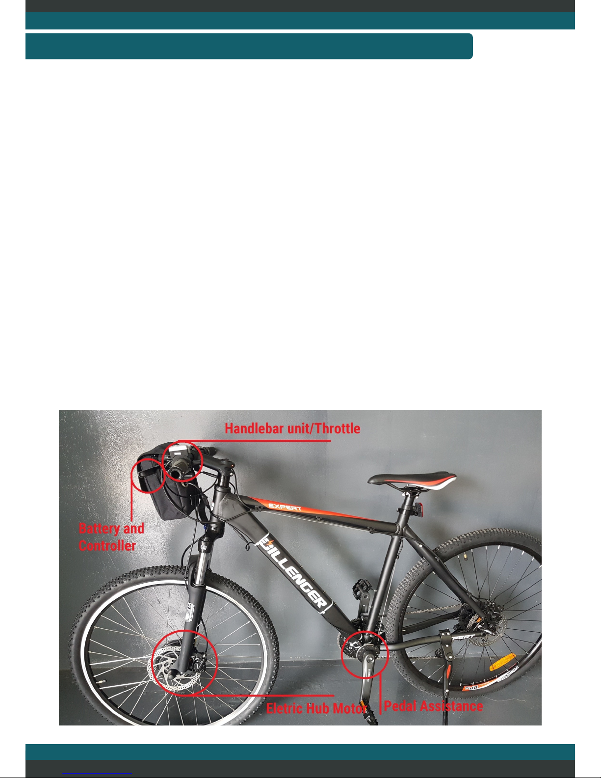
This section will help you understand the operation of an electric bicycle and the
common terms and components involved. Some or all of these components will
be in the conversion kit. If you are familiar with what an electric bike is and how it
operates, then feel free to skip over this section.
An electric bike consists of multiple complex electronic components that are
powered from a central location, the battery. The most common components of
an electric bike are:
A) Electric Motor
B) Motor Controller
C) Battery
D) LCD/Handlebar Display
E) Throttle
F) Pedal Assistance Sensor and Magnet Ring
G) Electric Brake Cut-offs (E-brake cut-offs) (not included in this model)
EBIKE COMPONENTS AND TERMINOLOGY

USER MANUAL ARC
LAST UPDATED: 6/01/2017 5
A) Electric Motor
The muscle of the electric bike, this component is what applies the rotational
force to the wheels and propels the bicycle forward. In most cases these motors
are a hub type motor meaning that the motor is built onto the wheel or axle. Some
motors will be located near the bicycle pedals and are called mid-drive or crank
drive motors.
B) Motor Controller
The main brain of the electric bike. This device takes in inputs from other
components and operates the motor. A very complex piece of electronics. This is
generally built into the frame of the electric bicycle somewhere, though can be
found attached to the motor or frame of the bicycle.
C) Battery
The heart of the electric bike. Without this electronic component there will be no
speedy take offs and smooth runs over hills. The battery of an electric bike is
generally a Lithium Ion type (though some are still lead acid). They have battery
management systems that ensure the safe operation and charging of the battery.
D) LCD/Handlebar Display (not featured in this model)
The second brain of the electric bike. This component takes in input from the rider
and provides it to the motor controller. Or uses the information to restrict the
motor controllers operation. This device usually allows the rider to change pedal
assistance levels, check battery levels and provide other functions/displays.
E) Throttle
This device is controlled by the rider usually located on the handlebar. If the rider
operates this device the motor controller will detect its operation and propel the
bike based on the amount of throttle utilised.
F) Pedal Assistance Sensor and Magnet Ring
This device is another input to the motor controller. It will detect the rotation of
the pedals and tell the motor controller of this. The motor controller will then
activate power to the motor based on the setting on the LCD/handlebar display.
G) Electric Brake Cut-offs (E-brake cut-offs) (not included in this model)
This component is either attached to the brakes or built in to the brakes. It detects
the actuation of the brakes and cuts the motor off. This is an added safety feature
built into most pedal assistance based electric bikes.

USER MANUAL ARC
LAST UPDATED: 6/01/2017 6
This section will help complete the initial installation of the electric bike kit. This
will detail installation for each component onto the electric bike. We recommend
you follow this guide very carefully and concisely..
ASSEMBLY
Unboxing your new electric bike kit can be an exciting prospect. Though we
recommend caution while unpacking the bike. It can be easy to get a bit
enthusiastic and accidently scratch the side of your kit with a cardboard knife or
pair scissors.
Carefully unwrap your electric bike kit by removing all packaging foam and
wrapping from each section of the bicycle kit. As mentioned above carefully
utilise tools such as knifes and snips to remove the packaging as it can be easy to
mark the paint work in this situation.
ASSEMBLY—UNBOXING

USER MANUAL ARC
LAST UPDATED: 6/01/2017 7
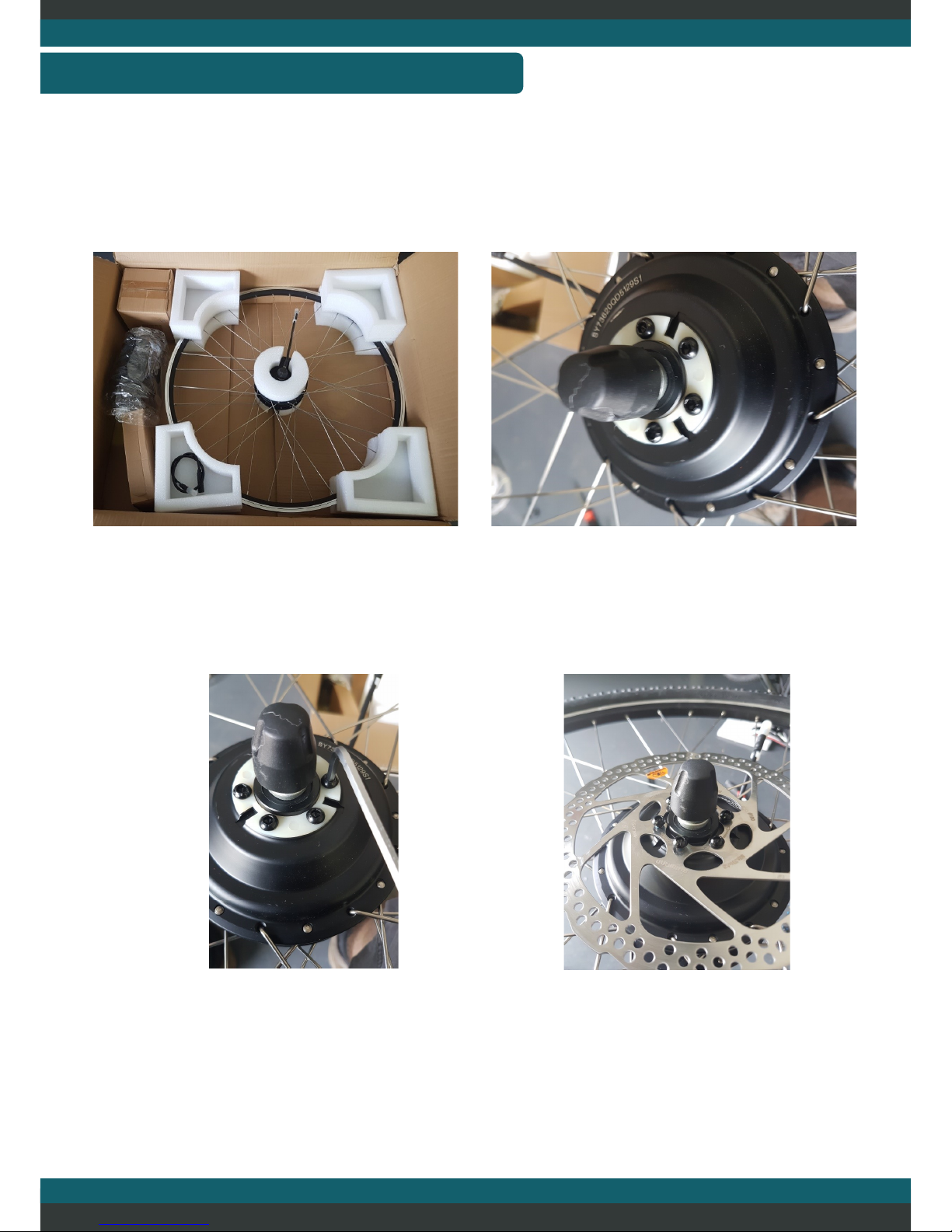
This is what the inside of the carton is likely to look like. The motor on the right
side, battery in the middle left, charger bottom left and the other parts and
accessories in the top left box.
TOOLS REQUIRED:
Spanner set or shifting spanner
Set of allen keys
Pair of side cutters/scissors
Tyre levers (not always necessary)
Additional zip ties (optional)
Strong adhesive (optional)
ASSEMBLY—INVENTORY

USER MANUAL ARC
LAST UPDATED: 6/01/2017 8
This section will detail some of the basic step you will need to undertake to
prepare your bicycle for conversion.
ASSEMBLY—BICYCLE PREPERATION
First thing you will need to do is nd a suitable space for you to complete the
installation in. If you don’t have a nice soft surface to ip the bike over onto (or
don’t have a bike maintenance stand) then we recommend that you utilise some
of the foam that comes in the kit to prevent any damage to your bike.
As pictured, we have ipped the bike over in preparation for removing the front
wheel to mount the motor. In this particular case the front wheel was quick
release making it very easy to remove without tools. Though you may require a
spanner/shifter at this stage to remove the front wheel.

USER MANUAL ARC
LAST UPDATED: 6/01/2017 9
Once the wheel has been removed, if your bicycle has a front disk brake. Then you
will need to remove that disk brake to mount onto the front motor.
ASSEMBLY—BICYCLE PREPERATION
Some disk brakes may require specialist tools to remove. Though most will only
require a standard 5mm allen key. Once you have removed the disk brake place it
aside for the next step.
Unless you purchased a new tyre and tube to go with the new motor, you will also
require the front tyre and tube to removed so that you can relocate it to the hub
motor from the conversion kit. Deate the tyre and remove the tyre and tube. This
usually can be done by hand though may require some tyre levers to help get the
job done. Avoid using tyre levers if possible though as they will increase your
chances of creating an accidental puncture in the tube. Just start on the opposite
side of the tubes valve, removing the tyre from the rim and work your way around
until the tyre is completely removed.
USER MANUAL ARC
LAST UPDATED: 6/01/2017 10
Now that the bicycle has been prepared. The motor can be mounted on the
bicycle.
ASSEMBLY—FRONT MOTOR
First remove the motor from its packaging if you have not done this already. It is
at this point that you can remount the tyre and tube, just make sure you get the
direction right. This is generally marked on the side of tyre tube. The motor has a
cable coming out of the right side which may help you get the correct direction.
If you have removed a disk brake in the previous section you should remount it on
the motor now. To do this you can remove the allen key bolts from the motor as
shown above. The motor has a plastic spacer in the position of the disk brake as a
placeholder. Remove this and mount the disk brake in position. Be sure to tighten
the bolts evenly all the way round.
Other manuals for FEATHER
1
Table of contents


