Arcam HDA PA720 User manual

HANDBOOK
EN
POWER AMPLIFIER
PA720 / PA240 / PA410

EN-2
Safety Guidelines
Important Safety Instructions
1. Read these instructions.
2. Keep these instructions.
3. Heed all warnings.
4. Follow all instructions.
5. Do not use this apparatus near water.
6. Clean only with dry cloth.
7. Do not block any ventilation openings. Install in
accordance with the manufacturer’s instructions.
8. Do not install near any heat sources such as radiators,
heat registers, stoves, or other apparatus (including
amplifiers) that produce heat.
9. Do not defeat the safety purpose of the polarized or
grounding-type plug.
A polarized plug has two blades with one wider
than the other. A grounding type plug has two
blades and a third grounding prong. The wide blade
or the third prong are provided for your safety. If the
provided plug does not fit into your outlet, consult
an electrician for replacement of the obsolete outlet.
10. Protect the power cord from being walked on
or pinched particularly at plugs, convenience
receptacles, and the point where they exit from the
apparatus.
11. Only use attachments/accessories specified by the
manufacturer.
12. Use only with the cart, stand, tripod, bracket, or
table specified by the manufacturer, or sold with the
apparatus.
When a cart is used, use caution
when moving the cart/apparatus
combination to avoid injury from tip-
over.
13. Unplug this apparatus during lightning storms or
when unused for long periods of time.
14. Refer all servicing to qualified service personnel.
Servicing is required when the apparatus has been
damaged in any way, such as power-supply cord or
plug is damaged, liquid has been spilled or objects
have fallen into the apparatus, the apparatus has
been exposed to rain or moisture, does not operate
normally, or has been dropped.
15. Object or liquid entry
WARNING – Take care that objects do not fall and
liquids are not spilled into the enclosure through
any openings. The equipment shall not be exposed
to dripping or splashing. Liquid-filled objects such
as vases should not be placed on the equipment.
16. Climate
The equipment has been designed for use in
moderate climates and in domestic situations.
17. Cleaning
Unplug the unit from the mains supply before
cleaning.
The case should normally only require a wipe with
a soft, lint-free cloth. Do not use chemical solvents
for cleaning.
We do not advise the use of furniture cleaning
sprays or polishes as they can cause permanent
white marks.
18. Power sources
Only connect the equipment to a power supply of
the type described in the operating instructions or
as marked on the equipment.
The primary method of isolating the equipment
from the mains supply is to remove the mains plug.
The equipment must be installed in a manner that
makes disconnection possible.
19. Abnormal smell
If an abnormal smell or smoke is detected from the
equipment, turn the power off immediately and
unplug the equipment from the wall outlet. Contact
your dealer and do not reconnect the equipment.
20. Damage requiring service
The equipment should be serviced by qualified
service personnel when:
A. The power-supply cord or the plug has been
damaged, or
B. Objects have fallen, or liquid has spilled into the
equipment, or
C. The equipment has been exposed to rain, or
D. The equipment does not appear to operate
normally or exhibits a marked change in
performance, or
E. The equipment has been dropped or the
enclosure damaged.
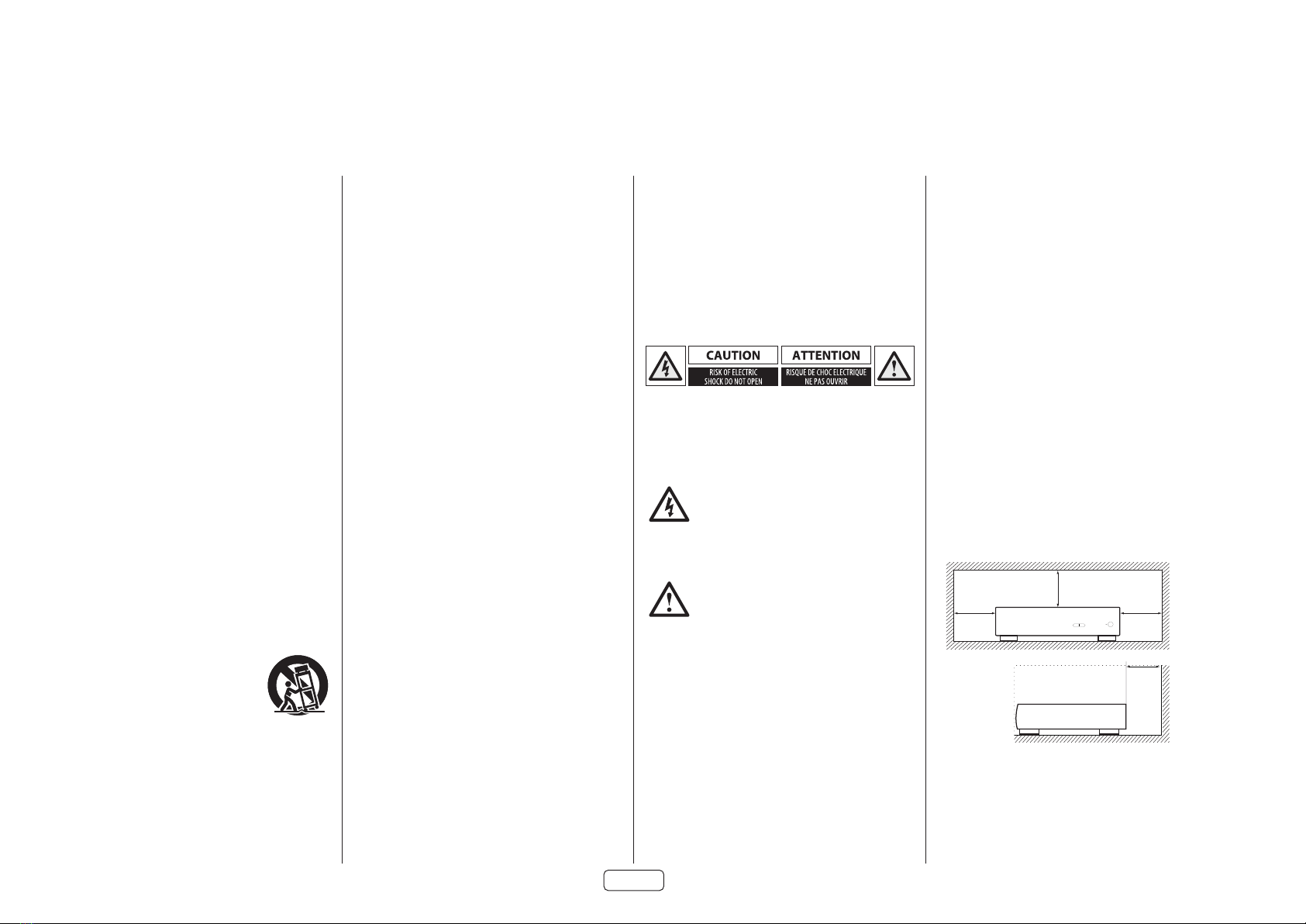
CAUTION: To reduce the risk of electric shock, do not
remove cover (or back). No user serviceable parts inside.
Refer servicing to qualified service personnel.
WARNING: To reduce the risk of fire or electric shock, do
not expose this apparatus to rain or moisture.
The lightning flash with an arrowhead
symbol within an equilateral triangle, is
intended to alert the user to the presence of
uninsulated ‘dangerous voltage’ within the
product’s enclosure that may be of sufficient magnitude
to constitute a risk of electric shock to persons.
The exclamation point within an equilateral
triangle is intended to alert the user to the
presence of important operating and
maintenance (servicing) instructions in the
literature accompanying the product.
CAUTION: In Canada and the USA, to prevent electric
shock, match the wide blade of the plug to the wide slot
in the socket and insert the plug fully into the socket.
Class II product
This equipment is a Class II or double insulated electrical
appliance. It has been designed in such a way that it
does not require a safety connection to electrical earth
(“ground” in the U.S.)
Warning
Mains plug/appliance coupler is used to disconnect
device and it shall remain readily operable.
Safety Compliance
This equipment has been designed to meet the IEC/EN
62368-1 international electrical safety standard.
This device complies with Part 15 of the FCC Rules.
Operation is subject to the following two conditions:
1. This device may not cause harmful interference, and
2. This device must accept any interference received,
including interference that may cause undesired
operation.
The building installation shall be regarded as providing
protection in accordance with the rating of the wall
socket outlet.
Caution on installation
For proper heat dispersal, do not install this unit in a
confined space, such as a bookcase or similar enclosure.
More than 0.3m (12in) is recommended.
Do not place any other equipment on this unit.
zz
z
Wall
z

EN
EN-3
FCC Information(for US
customers)
PRODUCT
This product complies with Part 15 of the FCC Rules.
Operation is subject to the following two conditions:
1. This device may not cause harmful interference, and
2. This device must accept any interference received,
including interference that may cause undesired
operation.
IMPORTANTNOTICE:DONOTMODIFYTHISPRODUCT
This product, when installed as indicated in the
instructions contained in this manual, meets FCC
requirements. Modification not expressly approved by
ARCAM may void your authority, granted by the FCC, to
use the product.
NOTE
This product has been tested and found to comply with
the limits for a Class B digital device, pursuant to Part 15
of the FCC Rules. These limits are designed to provide
reasonable protection against harmful interference in a
residential installation.
This product generates, uses and can radiate radio
frequency energy and, if not installed and used in
accordance with the instructions, may cause harmful
interference to radio communications. However, there
is no guarantee that interference will not occur in a
particular installation. If this product does cause harmful
interference to radio or television reception, which can
be determined by turning the product OFF and ON, the
user is encouraged to try to correct the interference by
one or more of the following measures:
Reorient or relocate the receiving antenna.
Increase the separation between the equipment and
receiver.
Connect the product into an outlet on a circuit
different from that to which the receiver is connected.
Consult the local retailer authorized to distribute
this type of product or an experienced radio/TV
technician for help
Safety Information (for European
customers)
Avoid high temperatures. Allow for sufficient heat
dispersion when installed in a rack.
Handle the power cord carefully. Hold the plug when
unplugging the cord.
Keep the unit free from moisture, water, and dust.
Unplug the power cord when not using the unit for
long periods of time.
Do not obstruct the ventilation holes.
Do not let foreign objects into the unit.
Do not let insecticides, benzene, and thinner come in
contact with the unit.
Never disassemble or modify the unit in any way.
Ventilation should not be impeded by covering the
ventilation openings with items, such as newspapers,
tablecloths or curtains.
Naked flame sources such as lighted candles should
not be placed on the unit.
Observe and follow local regulations regarding
battery disposal.
Do not expose the unit to dripping or splashing
fluids.
Do not place objects filled with liquids, such as vases,
on the unit.
Do not handle the mains cord with wet hands.
When the switch is in the OFF position, the equipment
is not completely switched off from MAINS.
The equipment shall be installed near the power
supply so that the power supply is easily accessible.
A note about recycling
This product’s packaging materials are recyclable
and can be reused. Please dispose of any materials in
accordance with the local recycling regulations.
When discarding the unit, comply with local rules or
regulations.
Batteries should never be thrown away or incinerated
but disposed of in accordance with the local
regulations concerning battery disposal.
This product and the supplied accessories, excluding
the batteries, constitute the applicable product
according to the WEEE directive.
Correct disposal of this product
These markings indicate that this product should not be
disposed with other household waste throughout the
EU.
To prevent possible harm to the environment or
human health from uncontrolled waste disposal and
to conserve material resources, this product should be
recycled responsibly.
To dispose of your product, please use your local return
and collection systems or contact the retailer where the
product was purchased.
Pb

EN-4
Welcome
Thank you and congratulations...
...for purchasing your Arcam PA720, PA240 or PA410 power amplifier.
Arcam has been producing specialist audio products of remarkable quality for over four decades and the new
PA720, PA240 and PA410 power amplifiers are the latest in a long line of award-winning Hi-Fi. The design of the HDA
range draws upon all of Arcam’s experience as one of the UK’s most respected audio companies, to produce Arcam’s
best performing range of multi channel power amplifiers yet – designed and built to give you years of listening
enjoyment.
This handbook is a guide to installing and using the PA720, PA240 and PA410 and includes information on the more
advanced features. Use the contents list on the next page to guide you to the section of interest.
We hope that your product will give you years of trouble-free operation. In the unlikely event of any fault, or if you
simply require further information about Arcam products, our network of dealers will be happy to help you. Further
information can also be found on the Arcam website at www.arcam.co.uk.
Your PA720, PA240 and PA410 development team

EN
EN-5
Safety Guidelines EN-2
Welcome EN-4
Overview EN-6
Placing The Unit EN-6
Interconnect Cables EN-6
Power EN-6
Rear Panel Connections and Controls PA720 EN-7
Rear Panel Connections and Controls PA240 EN-8
Rear Panel Connections and Controls PA410 EN-9
Control System Connections EN-10
Network and RS232 EN-10
USB EN-10
Trigger IN/OUT EN-10
Contents
Front Panel Connections and Controls EN-11
Operation EN-12
Switching On EN-12
Automatic Standby EN-12
Network and RS322 in Standby EN-12
Muting the Output EN-12
Mode switches EN-12
Connecting Sources and Loudspeakers EN-13
Bridged Mono Mode - PA240 only EN-16
Dual Mono / Bi Amp Mode - PA240 only EN-17
Troubleshooting EN-18
Specications EN-19
PA720 EN-19
PA240 EN-20
PA410 EN-21
Worldwide Guarantee EN-22

EN-6
Overview
PA720
POWER AMPLIFIER
POWER
STANDBYMUTE
Arcam’s PA720, PA240 and PA410
ampliers
Arcam’s PA720, PA240 and PA410 power amplifiers
provide class leading sound quality for the best
reproduction of your music.
Drawing on the many years of amplifier design
experience at Arcam, these products use the best
quality components and engineering practice to
produce amplifiers that will give many years of musical
pleasure and reliable service.
With a toroidal based power supply, acoustically
damped chassis, class G technology (PA240 &
PA720), parallel transistor output stages (PA240) and
exceptionally low levels of distortion and noise, the
PA720, PA240 and PA410 amplifiers are all capable of
reproducing music with all its original authority and
detail. Rest assured you will be hearing the music just as
the artist intended.
The PA720, PA240 and PA410 amplifiers are designed
to produce a level of performance that will truly bring
music to life.
Placing The Unit
Place the amplifier on a level, firm surface, avoiding
direct sunlight and sources of heat or damp.
Do not place the PA720, PA240 or PA410 on top of a
power amplifier or other source of heat.
Do not place the amplifier in an enclosed space such
as a bookcase or closed cabinet unless there is good
provision for ventilation. The PA720, PA240 and PA410
are designed to run warm during normal operation.
Do not place any other component or item on top
of the amplifier as this may obstruct airflow around
the heat-sink, causing the amplifier to run hot. (The
unit placed on top of the amplifier would become
hot, too).
Power
The amplifier is supplied with a moulded mains plug
already fitted to the lead. Check that the plug supplied
fits your supply – should you require a new mains lead,
please contact your Arcam dealer.
If your mains supply voltage or mains plug is different,
please contact your Arcam dealer immediately.
Push the IEC plug end of the power cable into the power
socket on the back of the amplifier, making sure that it
is pushed in firmly. Plug the other end of the cable into
your mains socket and switch the socket on.
Do not place your record deck on top of this
unit. Record decks are very sensitive to the noise
generated by mains power supplies which will be
heard as a background‘hum’if the record deck is too
close.
The normal function of the unit may be disturbed by
strong electromagnetic interference. If this occurs,
simply reset the unit with the power button, or move
the unit to another location.
Interconnect Cables
We recommend the use of high-quality screened cables
that are designed for the particular application. Other
cables will have different impedance characteristics
that will degrade the performance of your system (for
example, do not use cabling intended for video use to
carry audio signals). All cables should be kept as short as
is practically possible.
It is good practice when connecting your equipment to
make sure that the mains power-supply cabling is kept
as far away as possible from your audio cables. Failure to
do so may result in unwanted noise in the audio signals.

EN
EN-7
RS232 NET
TRIGGER OUT
(12V 100mA)
TRIGGER IN
POWER INLET
110-120V/220-240V~
50/60Hz 1.5kW MAX
USB
5V
100mA
SWITCH POSITIONS
115 = 110 - 120V ~
230 = 220 - 240V ~
SUPPLY
VOLTAGE
RCA XLR
INPUT
IN7
OUT7
IN6
OUT6
IN5
OUT5
IN4
OUT4
IN3
OUT3
IN2
OUT2
IN1
OUT1
IN7 IN6 IN5 IN4 IN3 IN2 IN1
CH4 CH3 CH2 CH1
4-16 OHMSCLASS 2 WIRING
CH5CH6CH7
Rear Panel Connections and Controls PA720
POWER INLET
Connect the correct mains cable
here.
VOLTAGE SELECT
Ensure that the voltage
selected matches the local
power supply.
PRE-AMPLIFIER INPUTS
Connect the phono outputs of your
pre-amplifier.
See “Connecting Sources and
Loudspeakers”on page EN-13.
SPEAKER TERMINALS
See “Connecting Sources
and Loudspeakers”on
page EN-13.
TRIGGER IN / OUT
Trigger IN allows the PA720 to be turned on or off by an external source.
Trigger OUT allows the PA720 to control the power state of other connected
equipment
See “Trigger IN/OUT” on page EN-10.
USB
For software upgrades only.
See “USB”on page EN-10.
NETWORK
This connection allows for remote control
from a third-party home automation system or
computer.
See “Network and RS232”on page EN-10.
RS232
This connection allows for remote control
from a third-party home automation
system or computer.
See “Network and RS232”on page EN-10.
BALANCED XLR AUDIO INPUTS
Connect the XLR outputs of your pre-
amplifier.
See “Connecting Sources and
Loudspeakers”on page EN-13.
INPUT SWITCHES
Allow the PA720 to be configured to
different input types
See “Connecting Sources and
Loudspeakers”on page EN-13.
PRE-AMPLIFIER OUTPUT
OUT1-OUT7 provide a copy of
the signal applied to the IN1-IN7
phono sockets only, not the XLR.
Note: This is a passive output,
no additional filtering or
amplification is applied.
Please read the sections “Placing The Unit”,
“Power” and “Interconnect Cables” on page
EN-6 before connecting your PA720
amplier!

EN-8
POWER INLET
Connect the correct mains cable
here.
VOLTAGE SELECT
Ensure that the voltage
selected matches the local
power supply.
PRE-AMPLIFIER INPUTS
Connect the phono outputs of your
pre-amplifier.
See “Connecting Sources and
Loudspeakers”on page EN-13.
SPEAKER TERMINALS
See “Connecting Sources
and Loudspeakers”on
page EN-13.
Please read the sections “Placing The Unit”,
“Power” and “Interconnect Cables” on page
EN-6 before connecting your PA240
amplier!
TRIGGER IN / OUT
Trigger IN allows the PA240 to be turned on or off by an external source.
Trigger OUT allows the PA240 to control the power state of other connected
equipment
See “Trigger IN/OUT” on page EN-10.
USB
For software upgrades only.
See “USB”on page EN-10.
NETWORK
This connection allows for remote control
from a third-party home automation system or
computer.
See “Network and RS232”on page EN-10.
RS232
This connection allows for remote control
from a third-party home automation
system or computer.
See “Network and RS232”on page EN-10.
Rear Panel Connections and Controls PA240
RS232 NET
TRIGGER OUT
(12V 100mA)
TRIGGER IN
POWER INLET
110-120V/220-240V~
50/60Hz 1.5kW MAX
USB
5V
100mA
SWITCH POSITIONS
115 = 110 - 120V ~
230 = 220 - 240V ~
SUPPLY
VOLTAGE
RCA XLR
INPUT
+
4-16 OHMS. CLASS 2 WIRING
+
- -
R
ST BRIDGE DM
GAIN
25dB 31dB
MODE
L
INR INL
INR
OUTR
INL
OUTL
BALANCED XLR AUDIO INPUTS
Connect the XLR outputs of your pre-
amplifier.
See “Connecting Sources and
Loudspeakers”on page EN-13.
INPUT SWITCHES
Allow the PA240 to be configured in
different operational modes.
See “Connecting Sources and
Loudspeakers”on page EN-13.
PRE-AMPLIFIER OUTPUT
OUTL and OUTR provide a copy of
the signal applied to the IN L and IN
R phono sockets only, not the XLR.
Note: This is a passive output,
no additional filtering or
amplification is applied.

EN
EN-9
POWER INLET
110-120V/220-240V ~ 50/60Hz
500W MAX
SUPPLY
VOLTAGE
SWITCH POSITIONS
115 = 110 - 120V ~
230 = 220 - 240V ~
RS232NET USB
5V 100mA
CH1
4-16 OHMS
CLASS 2 WIRING
CH2CH3CH4
IN4
OUT4
IN3
OUT3
IN2
OUT2
IN1
OUT1
TRIGGER OUT
(12V 100mA)
TRIGGER IN
POWER INLET
Connect the correct mains cable
here.
VOLTAGE SELECT
Ensure that the voltage
selected matches the local
power supply.
PRE-AMPLIFIER INPUTS
Connect the phono outputs of your
pre-amplifier.
See “Connecting Sources and
Loudspeakers”on page EN-13.
SPEAKER TERMINALS
See “Connecting Sources
and Loudspeakers”on
page EN-13.
TRIGGER IN / OUT
Trigger IN allows the PA410 to be turned on or off by an external source.
Trigger OUT allows the PA410 to control the power state of other connected
equipment
See “Trigger IN/OUT” on page EN-10.
USB
For software upgrades only. See
“USB” on page EN-10.
NETWORK
Connect your wired local network to one port.
The second port can be used to connect to
other devices
See “Network and RS232”on page EN-10.
RS232
This connection allows for remote control
from a third-party home automation
system or computer.
See “Network and RS232”on page EN-10.
Rear Panel Connections and Controls PA410
PRE-AMPLIFIER OUTPUT
OUT1 to OUT4 provide a copy
of the signal applied to the
IN1 to IN4 phono sockets.
Note: This is a passive output,
no additional filtering or
amplification is applied.
Please read the sections “Placing The Unit”,
“Power” and “Interconnect Cables” on page
EN-6 before connecting your PA410
amplier!

EN-10
Network and RS232
The PA720, PA240 and PA410 feature a network and
RS232 port that can be used to connect to a local
network, computer or home automation sytem so that
the amplifier can be controlled and monitored remotely.
Various third party systems are available providing
sophisticated control over all of your entertainment
devices. Contact your dealer or installer for details.
For technical details of control protocols please refer to
the PA720 / PA240 / PA410 RS232/IP control document,
availbale for download at www.arcam.co.uk, for
further information.
Note: By default, network and RS232 control is disabled
in standby to minimise standby power consumption.
To enable network control see “Network and RS322 in
Standby” on page EN-12.
USB
The USB port is used for software updates only. For the
latest software as well as further information, please visit
www.arcam.co.uk.
Trigger IN/OUT
The power state of the PA720, PA240 and PA410 can
be controlled by compatible audio/video sources
(such as an Arcam AVR). In this case, connect the
TRIGGER OUT of the source to the TRIGGER IN of the
PA720, PA240 or PA410 using a mono 3.5mm jack lead.
Similarly, the PA720, PA240 and PA410 can control the
power state of compatible product (such as another
PA720, PA240 or PA410). In this case, connect the
TRIGGER IN of the source to the TRIGGER OUT of the
PA720, PA240 or PA410 using a mono 3.5mm jack.
Note:These leads are not supplied.
RS232 NET
TRIGGER OUT
(12V 100mA)
TRIGGER IN
POWER INLET
110-120V/220-240V~
50/60Hz 1.5kW MAX
USB
5V
100mA
SWITCH POSITIONS
115 = 110 - 120V ~
230 = 220 - 240V ~
SUPPLY
VOLTAGE
RCA XLR
INPUT
IN7
OUT7
IN6
OUT6
IN5
OUT5
IN4
OUT4
IN3
OUT3
IN2
OUT2
IN1
OUT1
IN7 IN6 IN5 IN4 IN3 IN2 IN1
CH4 CH3 CH2 CH1
4-16 OHMSCLASS 2 WIRING
CH5CH6CH7
NET
RS232
1 2 3 4NET
Network Router
Home Automation Controller
115 230
SWITCH POSITIONS
115 = 110 - 115V~
230 = 220 - 240V~
HEIGHT1 HEIGHT2
SUB 2
L
R
PREAMP OUT
FL C SL SBL
FR SUB 1 SR SBR
BD CD
PVRSAT DIGITAL AUDIO
STB AV
OUTPUT 2 OUTPUT 1
ARC
ZONE 2
OUT
PVR
VCR
BD
SAT
AV
GAME
STB/MHL
HDMI
L
R
Z2 OUT STB GAME AV BD PVR CD
ANALOGUE AUDIO
ETHERNET
USB 5V 1A
FM/DAB
DC 6V
1.2A MAX RS232
TRIG Z1 Z1 IR
TRIG Z2 Z2 IR
23425
POWER INLET
~50/60Hz 50W MAX
BALANCED OUTPUTS
FL C SL SBL HEIGHT 1 L HEIGHT 2 L
FR SUB 1 SR SBR HEIGHT 1 R HEIGHT 2 R
PA720
AV860
PA410
Control System Connections
POWER INLET
110-120V/220-240V ~ 50/60Hz
500W MAX
SUPPLY
VOLTAGE
SWITCH POSITIONS
115 = 110 - 120V ~
230 = 220 - 240V ~
RS232NET USB
5V 100mA
CH1
4-16 OHMS
CLASS 2 WIRING
CH2CH3CH4
IN4
OUT4
IN3
OUT3
IN2
OUT2
IN1
OUT1
TRIGGER OUT
(12V 100mA)
TRIGGER IN

EN
EN-11
PA720
POWER AMPLIFIER
POWER
STANDBYMUTE
Front Panel Connections and Controls
MUTE
Mute / unmute the PA720, PA240 or PA410 speaker outputs.
See “Muting the Output” on page EN-12.
UNIT STANDBY
See “Switching On”on page EN-12.
POWER INDICATOR AND POWER
SWITCH
See “Switching On”on page EN-12.

EN-12
Operation
Switching On
The POWER button switches the unit on and off. The
status indicator LED indicates the state of the amplifier:
it changes from red to orange then white if mains
power is connected and the unit is switched on.
Pressing the STBY button while the unit is powered
on, will place the PA720, PA240 or PA410 into standby
mode. Press the STBY button again to bring the unit out
of standby.
Automatic Standby
In order to comply with international regulations for
consumer products, this unit is designed to enter
standby mode if no user interaction and no audio input
signal are detected for an extended period of time
(default is 20 minutes). The unit can be brought out of
standby by pressing the STBY button on the front panel,
the trigger input or RS232 or ethernet command (if
enabled, see “Network and RS322 in Standby” for more
information)
The standby time out can be adjusted using either
RS232 or IP control commands. Please refer to the
PA720 / PA240 / PA410 RS232/IP control document,
available for download from www.arcam.co.uk.
Alternatively pressing and holding the MUTE button
will toggle the standby time out between OFF and 20
minutes.
The LED will flash to indicate the setting change, red for
OFF, green for 20 minutes.
Note: if the standby time-out is set to OFF, the automatic
standby feature will be disabled.
Network and RS322 in Standby
In low power standby mode the network and RS322
functionality is disabled.
To enable network and RS232 in standby, send a control
or status request command to the unit whilst it is
powered on.
This will enable whichever control method was used
when the unit is in standby.
Note: To indicate the unit is not in lowest power standby
mode the LED will flash briefly when entering standby
mode.
Note: Enabling network or RS232 control will increase
standby power consumption. To restore the unit to
the default low power standby consumption press and
hold the STBY button for more than 3 seconds or restore the unit to
factorydefaults.
Mode switches
The various mode switches located on the rear of the
PA720 and PA240 amplifiers allow you to configure your
power amplifier to your specific equipment setup. See
“Connecting Sources and Loudspeakers”on page EN-13
for more information.
INPUT (PA720 and PA240 only)
This switch selects between the XLR and RCA phono
inputs of the amplifier. Select which ever connection
method you are using to connect your preamp.
GAIN(PA240 only)
This switch allows the gain to be changed from standard
Arcam gain of 31dB (which matches all Arcam amplifiers
and receivers) to 26dB. This allows flexibility to connect
multiple PA240 amplifiers in different modes to multiple
speakers.
In normal set-ups this switch should be left at 31dB.
MODE (PA240 only)
This switch selects between the different amplification
modes of the PA240.
STEREO (ST)
This is the standard stereo amplification mode using
two separate preamp inputs driving two separate
speaker outputs.
DUAL MONO (DM)
This mode allows two separate speakers to be driven
from a single preamp input.
Alternatively the two drivers of a single speaker can be
bi-amped from a single PA240.
BRIDGED MONO (BRIDGE)
This mode uses both channels of the PA240 to drive a
single speaker. This the ultimate in high power, high
fidelity amplification.
Muting the Output
The speaker outputs of the PA720, PA240 or PA410 can
be silenced by pressing the MUTE button on either the
front panel or by sending the relevent command via
either the RS232 or network connection.
If the unit is muted, front panel power indicator will
change to orange.
To cancel the mute, press the MUTE button again or
send the relevent command via either the RS232 or
network connection.

EN
EN-13
HF
LF
Connecting Sources and Loudspeakers
RS232 NET
TRIGGER OUT
(12V 100mA)
TRIGGER IN
POWER INLET
110-120V/220-240V~
50/60Hz 1.5kW MAX
USB
5V
100mA
SWITCH POSITIONS
115 = 110 - 120V ~
230 = 220 - 240V ~
SUPPLY
VOLTAGE
RCA XLR
INPUT
IN7
OUT7
IN6
OUT6
IN5
OUT5
IN4
OUT4
IN3
OUT3
IN2
OUT2
IN1
OUT1
IN7 IN6 IN5 IN4 IN3 IN2 IN1
CH4 CH3 CH2 CH1
4-16 OHMSCLASS 2 WIRING
CH5CH6CH7
HF
LF
HF
LF
Notes On Making Speaker Connections
Do not make any connections to any amplifier while it is switched on. We recommend
that your amplifier is completely disconnected from the mains supply before starting.
Before switching your amplifier on for the first time after connecting to speakers, please
check all connections thoroughly. Ensure that bare wires or cables are not touching
each other or the amplifier’s chassis (which could cause short circuits), and that you
have connected positive (+) to positive and negative (–) to negative. Be sure to check
the wiring for both the amplifier and the speaker.
After making connections: switch the amplifier on then gradually increase the volume
to the required listening level.
If you are unsure as to how your system should be connected, please contact your
Arcam dealer who will be happy to help you.
115 230
SWITCH POSITIONS
115 = 110 - 115V~
230 = 220 - 240V~
HEIGHT1 HEIGHT2
SUB 2
L
R
PREAMP OUT
FL C SL SBL
FR SUB 1 SR SBR
BD CD
PVRSAT DIGITAL AUDIO
STB AV
OUTPUT 2 OUTPUT 1
ARC
ZONE 2
OUT
PVR
VCR
BD
SAT
AV
GAME
STB/MHL
HDMI
L
R
Z2 OUT STB GAME AV BD PVR CD
ANALOGUE AUDIO
ETHERNET
USB 5V 1A
FM/DAB
DC 6V
1.2A MAX RS232
TRIG Z1 Z1 IR
TRIG Z2 Z2 IR
23425
POWER INLET
~50/60Hz 50W MAX
BALANCED OUTPUTS
FL C SL SBL HEIGHT 1 L HEIGHT 2 L
FR SUB 1 SR SBR HEIGHT 1 R HEIGHT 2 R
AV860
HF
LF
PREAMP OUT
FL C SL SBL
FR
SUB 1
SR SBR
PA720
Connect the RED positive speaker terminal labelled
CH1 to CH7+ to the positive terminal of your speaker.
Similarly, connect the BLACK negative speaker terminal
of the same channel to the negative terminal of your
speaker.
Repeat this process for the other speakers, using the
same respective input and speaker terminals for each
channel.
NOTE: All the channels are identical so there is no
requirement to connect specific AVR output channels
to specific amplifier channels.
HF
LF
HF
LF
HF
LF
BALANCED OUTPUTS
FL C SL SBL
HEIGHT 1 L
HEIGHT 2 L
FR
SUB 1
SR SBR
HEIGHT 1 R
HEIGHT 2 R
RCA XLR
INPUT
Note: Single channel shown for
clarity
Note: Unit should be
connected via RCA
or XLR. Both versions
shown for illustrative
purposes only.
PA720

EN-14
HF
LF
HF
LF
Right Left
115 230
SWITCH POSITIONS
115 = 110 - 115V~
230 = 220 - 240V~
HEIGHT1 HEIGHT2
SUB 2
L
R
PREAMP OUT
FL C SL SBL
FR SUB 1 SR SBR
BD CD
PVRSAT DIGITAL AUDIO
STB AV
OUTPUT 2 OUTPUT 1
ARC
ZONE 2
OUT
PVR
VCR
BD
SAT
AV
GAME
STB/MHL
HDMI
L
R
Z2 OUT STB GAME AV BD PVR CD
ANALOGUE AUDIO
ETHERNET
USB 5V 1A
FM/DAB
DC 6V
1.2A MAX RS232
TRIG Z1 Z1 IR
TRIG Z2 Z2 IR
23425
POWER INLET
~50/60Hz 50W MAX
BALANCED OUTPUTS
FL C SL SBL HEIGHT 1 L HEIGHT 2 L
FR SUB 1 SR SBR HEIGHT 1 R HEIGHT 2 R
AV860
PA240
Connect the RED positive speaker terminal labelled
L+to the positive terminal of your speaker. Similarly,
connect the BLACK negative speaker terminal labelled
L to the negative terminal of your speaker.
Repeat this process for the right speaker.
RCA XLR
INPUT
+
4-16 OHMS. CLASS 2 WIRING
+
- -
R
ST BRIDGE DM
GAIN
25dB 31dB
MODE
L
INR INL
INR
OUTR
INL
OUTL
PREAMP OUT
FL
C
SL
SBL
FR
SUB 1
SR
SBR
FL
FR MODE
ST BRIDGE DM
GAIN
25dB 31dB RCA XLR
INPUT
Note: Unit should be connected via RCA or XLR.
Both versions shown for illustrative purposes
only.
Note:
Make sure INPUT switch is set to input type RCA or XLR
Make sure GAIN switch is set to 31dB
Make sure MODE switch is set to stereo mode, ST
PA240

EN
EN-15
HF
LF
HF
LF
HF
LF
Height 1 Right Height 1 Left
115 230
SWITCH POSITIONS
115 = 110 - 115V~
230 = 220 - 240V~
HEIGHT1 HEIGHT2
SUB 2
L
R
PREAMP OUT
FL C SL SBL
FR SUB 1 SR SBR
BD CD
PVRSAT DIGITAL AUDIO
STB AV
OUTPUT 2 OUTPUT 1
ARC
ZONE 2
OUT
PVR
VCR
BD
SAT
AV
GAME
STB/MHL
HDMI
L
R
Z2 OUT STB GAME AV BD PVR CD
ANALOGUE AUDIO
ETHERNET
USB 5V 1A
FM/DAB
DC 6V
1.2A MAX RS232
TRIG Z1 Z1 IR
TRIG Z2 Z2 IR
23425
POWER INLET
~50/60Hz 50W MAX
BALANCED OUTPUTS
FL C SL SBL HEIGHT 1 L HEIGHT 2 L
FR SUB 1 SR SBR HEIGHT 1 R HEIGHT 2 R
AV860
HF
LF
Height 2 Right Height 2 Left
PA410
Connect the RED positive speaker terminal labelled
CH1 to CH4+ to the positive terminal of your speaker.
Similarly, connect the BLACK negative speaker terminal
of the same channel- to the negative terminal of your
speaker.
Repeat this process for the other speakers, using the
same respective input and speaker terminals for each
channel.
NOTE: All the channels are identical so there is no
requirement to connect specific AVR output channels
to specific amplifier channels.
POWER INLET
110-120V/220-240V ~ 50/60Hz
500W MAX
SUPPLY
VOLTAGE
SWITCH POSITIONS
115 = 110 - 120V ~
230 = 220 - 240V ~
RS232NET USB
5V 100mA
CH1
4-16 OHMS
CLASS 2 WIRING
CH2CH3CH4
IN4
OUT4
IN3
OUT3
IN2
OUT2
IN1
OUT1
TRIGGER OUT
(12V 100mA)
TRIGGER IN
PA410
HEIGHT 1 HEIGHT 2
L
R
PREAMP OUT
SUB 2

EN-16
Bridged Mono Mode - PA240
only
Bridged mono mode requires the use of a PA240 for
each channel.
Note: In bridged mode only the L+ and R+ speaker
outputs are required.
WARNING: Do not make any connections to the L- or
R- speaker terminals, doing so will severely damage
your amplier.
On one of the PA240’s, connect the RED positive
speaker terminal labelled L+ to the positive terminal of
your left speaker.
Connect the RED positive speaker terminal labelled R+
to the negative terminal of your left speaker.
Repeat this process for the right speaker, using the
SAME terminals on the other PA240.
In this setup only one interconnect is required to
each power amplifier and it should be connected to
the IN L input. The interconnects can be either XLR
(recommended for longer cable runs) or phono (RCA).
Set the INPUT switch on both of the PA240’s to the
appropriate setting for the cables used.
Note: The IN R input has no function in this
arrangement.
Note: L+ must be connected to the positive speaker
terminal and R+ to the negative speaker terminal on
BOTH speakers otherwise the speakers will be out of
phase.
WARNING: Make ABSOLUTELY sure you have used the
L+ and R+ terminals of the PA240. L- and R- terminals
are NOT required in this arrangement.
RCA XLR
INPUT
+
4-16 OHMS. CLASS 2 WIRING
+
- -
R
ST BRIDGE DM
GAIN
25dB 31dB
MODE
L
INR INL
INR
OUTR
INL
OUTL
HF
LF
HF
LF
Right Left
RCA XLR
INPUT
+
4-16 OHMS. CLASS 2 WIRING
+
- -
R
ST BRIDGE DM
GAIN
25dB 31dB
MODE
L
INR INL
INR
OUTR
INL
OUTL
MODE
ST BRIDGE DM
GAIN
25dB 31dB
RCA XLR
INPUT
Note:
Make sure INPUT switch
is set to input type RCA
or XLR
It is recommended that the
GAIN switch is set to 25dB
Make sure MODE switch
is set to bridged mode,
BRIDGE
115 230
SWITCH POSITIONS
115 = 110 - 115V~
230 = 220 - 240V~
HEIGHT1 HEIGHT2
SUB 2
L
R
PREAMP OUT
FL C SL SBL
FR SUB 1 SR SBR
BD CD
PVRSAT DIGITAL AUDIO
STB AV
OUTPUT 2 OUTPUT 1
ARC
ZONE 2
OUT
PVR
VCR
BD
SAT
AV
GAME
STB/MHL
HDMI
L
R
Z2 OUT STB GAME AV BD PVR CD
ANALOGUE AUDIO
ETHERNET
USB 5V 1A
FM/DAB
DC 6V
1.2A MAX RS232
TRIG Z1 Z1 IR
TRIG Z2 Z2 IR
23425
POWER INLET
~50/60Hz 50W MAX
BALANCED OUTPUTS
FL C SL SBL HEIGHT 1 L HEIGHT 2 L
FR SUB 1 SR SBR HEIGHT 1 R HEIGHT 2 R
AV860
PREAMP OUT
FL
C
SL
SBL
FR
SUB 1
SR
SBR
FL
FR
Note: Unit should be connected via RCA or XLR.
Both versions shown for illustrative purposes
only.
PA240
PA240

EN
EN-17
Dual Mono / Bi Amp Mode - PA240 only
Dual mono requires the use of a PA240 for each channel.
On one of the PA240’s, connect the RED positive speaker
terminal labelled L+ to the positive LF terminal of your
left speaker. Similarly, connect the BLACK negative
speaker terminal labelled L- to the negative LF terminal
of your left speaker.
WARNING: Speakers that support biamping
have a metal strip that connects the low
frequency (LF) and high frequency (HF)
terminals. This MUST be removed in a bi-amped
system
Using a second speaker cable connect the RED positive
speaker terminal labelled R+ to the positive HF terminal
of your left speaker. Similarly, connect the BLACK
negative speaker terminal labelled R- to the negative
HF terminal of your speaker.
Repeat this process for the right speaker, using the same
terminals on the other PA240.
RCA XLR
INPUT
+ +
- -
R
ST BRIDGE DM
GAIN
25dB 31dB
MODE
L
INR INL
INR
OUTR
INL
OUTL
HF
LF
HF
LF
Right Left
RCA XLR
INPUT
+ +
- -
R
ST BRIDGE DM
GAIN
25dB 31dB
MODE
L
INR INL
INR
OUTR
INL
OUTL
MODE
ST BRIDGE DM
GAIN
25dB 31dB
RCA XLR
INPUT
Note:
Make sure INPUT switch
is set to input type RCA
or XLR
Make sure GAIN switch is
set to 31dB
Make sure MODE switch
is set to dual mono mode,
DM
115 230
SWITCH POSITIONS
115 = 110 - 115V~
230 = 220 - 240V~
HEIGHT1 HEIGHT2
SUB 2
L
R
PREAMP OUT
FL C SL SBL
FR SUB 1 SR SBR
BD CD
PVRSAT DIGITAL AUDIO
STB AV
OUTPUT 2 OUTPUT 1
ARC
ZONE 2
OUT
PVR
VCR
BD
SAT
AV
GAME
STB/MHL
HDMI
L
R
Z2 OUT STB GAME AV BD PVR CD
ANALOGUE AUDIO
ETHERNET
USB 5V 1A
FM/DAB
DC 6V
1.2A MAX RS232
TRIG Z1 Z1 IR
TRIG Z2 Z2 IR
23425
POWER INLET
~50/60Hz 50W MAX
BALANCED OUTPUTS
FL C SL SBL HEIGHT 1 L HEIGHT 2 L
FR SUB 1 SR SBR HEIGHT 1 R HEIGHT 2 R
AV860
PREAMP OUT
FL
C
SL
SBL
FR
SUB 1
SR
SBR
FL
FR
Note: Unit should be connected via RCA or XLR.
Both versions shown for illustrative purposes
only.
In this setup only one interconnect is required to
each power amplifier and it should be connected to
the IN L input. The interconnects can be either XLR
(recommended for longer cable runs) or phono (RCA).
Set the INPUT switch on both of the PA240’s to the
appropriate setting for the cables used.
Note: The IN R input has no function in this
arrangement.
PA240 PA240

EN-18
Troubleshooting
Problem Check the following
No sound The PA720 / PA240 / PA410 power amplifier is correctly plugged in and
switched on.
Your audio/video source (e.g. pre amplifier) is correctly connected.
The PA720 / PA240 / PA410 is not in protection mode, as described in
the next section.
The PA720, PA240 and PA410 is not muted.
Sound cuts-out unexpectedly The PA720 / PA240 / PA410 may enter a protection mode, depending on
the fault being detected. The front panel LED will indicate the fault type,
according to the list below.
FLASHING WHITE: The internal temperature of the unit reached an
unsafe level. Allow the PA720 / PA240 / PA410 to cool off.
FLASHING RED: The PA720 / PA240 / PA410 amplifier detected a
speaker short circuit. Should this happen, please inspect all the
speaker cables to make sure none of them are shorted together. This
fault is very common when bare wires are being used to make speaker
connections.
FLASHING ORANGE: PA720 and PA240 only. The amplifier detected a
DC offset.
Following any of the faults described above, the amplifier will turn itself
off and power to the speakers will be removed. To continue using the
PA720 / PA240 / PA410, the fault must be removed and the unit must be
turned OFF then back ON.

EN
EN-19
Specications
Continuouspoweroutputat0.2%THD per channel
Seven channels driven, 4Ω / 8Ω, 1kHz 140W / 100W
Five channels driven, 4Ω / 8Ω, 1kHz 175W / 110W
Two channels driven, 4Ω / 8Ω, 1kHz 225W / 140W
Harmonic distortion, 80% power, 8Ω at 1kHz 0.002%
Inputs
RCA Type XLR Type
Input sensitivity 100W / 8Ω 800mV RMS 1.6V RMS
Signal/Noise ratio (A-wtd) 100W / 8Ω 112dB
Input impedance 10kΩ
Frequency response 20 - 20kHz +/-0.05dB
General
Mains voltage 110–120V or 220–240V, 50–60Hz
Maximum power consumption 1.5kW
Low power standby consumption 0.5W
Network standby consumption 2W
Dimensions W x H x D (including feet,
control knob and speaker terminals)
433 x 425 x 177mm
Weight (net) 18kg
Weight (gross) 19.7kg
All specication values are typical unless otherwise
stated.Arcamhasapolicy ofcontinuousimprovement
for its products. This means that designs and
specications are subject to change without notice.
E&OE.
PA720

EN-20
Continuouspoweroutputat0.2%THD per channel
Two channels driven, 4Ω / 8Ω, 1kHz 380W / 225W
One channel driven,
8Ω bridged mode, 1kHz
790W
Harmonic distortion, 80% power, 8Ω at 1kHz 0.001%
Inputs
RCA Type XLR Type
31dB 25dB 31dB 25dB
Input sensitivity 200W / 8Ω 1.15V RMS 2.3V RMS 2.3V RMS 4.6V RMS
Signal/Noise ratio (A-wtd) 10W / 8Ω 110dB 114dB 110dB 114dB
Input impedance 10kΩ
Frequency response 20 - 20kHz +/-0.05dB
General
Mains voltage 110–120V or 220–240V, 50–60Hz
Maximum power consumption 1.5kW
Low power standby consumption 0.5W
Network standby consumption 2W
Dimensions W x H x D (including feet,
control knob and speaker terminals)
433 x 425 x 177mm
Weight (net) 18kg
Weight (gross) 19.7kg
All specication values are typical unless otherwise
stated.Arcamhasapolicy ofcontinuousimprovement
for its products. This means that designs and
specications are subject to change without notice.
E&OE.
PA240
Other manuals for HDA PA720
2
This manual suits for next models
2
Table of contents
Other Arcam Amplifier manuals