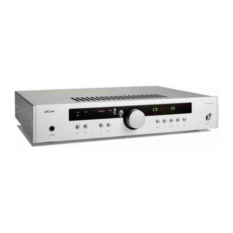
Arcam SA30 User manual

SERVICE MANUAL
INTEGRATED AMPLIFIER
SA30
ISSUE A

EN-2
Revision History
Issue A - Initial release

EN-3
Contents
Safety Summary EN-4
Safety Guidelines EN-5
Electrostatic Discharge (ESD) Precautions EN-7
General Information EN-8
SA30 Specications EN-9
Troubleshooting EN-10
Block Diagram EN-11
Theory of Operation EN-13
Power Amplier PCB - L297 EN-13
Digital PCB - L298 EN-13
Front Panel - L305 EN-13
These service instructions are only intended for use by
qualied personnel. Do not perform any servicing other than
that contained in these instructions unless qualied to do so.
Refer to the Safety Guidelines prior to performing any service
L297 Power Amplier PCB Issue 4 EN-14
L298 Digital PCB Issue 3 EN-37
L305 Display PCB Issue 3 EN-48
Overall Dimensions EN-53
Exploded Drawings EN-55

EN-4
Safety Summary
The following general safety precautions must be observed during all phases of operation, service, and repair of this unit. Failure to comply with these precautions or with specic warnings elsewhere in these instructions violates
manufacturer safety standards and intended use of this unit. Harman Luxury Audio Group assumes no liability for failure to comply with these requirements.
DO NOT OPERATE IN AN EXPLOSIVE ATMOSPHERE
Do not operate the unit in the presence of ammable gasses or fumes. Operation of any electrical instrument in such an environment constitutes a denite safety hazard.
KEEP AWAY FROM LIVE CIRCUITS
Operating personnel must not remove unit covers. Qualied maintenance personnel must make component replacements and internal adjustments. To avoid personal injuries, always disconnect power and discharge circuits before
touching them.
DO NOT SERVICE OR ADJUST ALONE
Do not attempt internal service or adjustment unless another person capable of rendering rst-aid resuscitation is present.
DO NOT SUBSTITUTE PARTS OR MODIFY INSTRUMENT
Because of the danger of introducing additional hazards, do not install substitute parts or perform any unauthorized modication to the unit.
DANGEROUS PROCEDURE WARNINGS
Warnings such as the example shown below precede potentially dangerous procedures throughout this document. Instructions contained in warnings must be followed.
WARNING
Dangerous voltages capable of causing death are present in this unit. Use extreme caution when handling, testing, or adjusting.

EN-5
Safety Guidelines
Read these instructions.
Keep these instructions.
Heed all warnings.
Follow all instructions.
Do not use this apparatus near water.
Clean only with dry cloth.
Do not block any ventilation openings. Install in
accordance with the manufacturer’s instructions.
Do not install near any heat sources such as radiators,
heat registers, stoves, or other apparatus (including
ampliers) that produce heat.
Do not defeat the safety purpose of the polarized or
grounding-type plug.
A polarized plug has two blades with one wider than
the other. A grounding type plug has two blades and
a third grounding prong. The wide blade or the third
prong are provided for your safety. If the provided plug
does not t into your outlet, consult an electrician for
replacement of the obsolete outlet.
Protect the power cord from being walked on or
pinched particularly at plugs, convenience receptacles,
and the point where they exit from the apparatus.
Only use attachments/accessories specied by the
manufacturer.
Use only with the cart, stand, tripod, bracket, or
table specied by the manufacturer, or sold with the
apparatus.
When a cart is used, use caution when moving the cart/
apparatus combination to avoid injury
from tip-over.
Unplug this apparatus during lightning
storms or when unused for long periods
of time.
Refer all servicing to qualied service personnel.
Servicing is required when the apparatus has been
damaged in any way, such as power-supply cord or
plug is damaged, liquid has been spilled or objects
have fallen into the apparatus, the apparatus has been
exposed to rain or moisture, does not operate normally,
or has been dropped.
Object or liquid entry
WARNING – Take care that objects do not fall and liquids
are not spilled into the enclosure through any openings.
The equipment shall not be exposed to dripping or
splashing. Liquid-lled objects such as vases should not
be placed on the equipment.
Climate
The equipment has been designed for use in moderate
climates and in domestic situations.
Cleaning
Unplug the unit from the mains supply before cleaning.
The case should normally only require a wipe with a
soft, lint-free cloth. Do not use chemical solvents for
cleaning.
We do not advise the use of furniture cleaning sprays
or polishes as they can cause permanent white marks.
Power sources
Only connect the equipment to a power supply of
the type described in the operating instructions or as
marked on the equipment.
The primary method of isolating the equipment from
the mains supply is to remove the mains plug. The
equipment must be installed in a manner that makes
disconnection possible.
Abnormal smell
If an abnormal smell or smoke is detected from the
equipment, turn the power o immediately and unplug
the equipment from the wall outlet. Contact your dealer
and do not reconnect the equipment.
Damage requiring service
The equipment should be serviced by qualied service
personnel when:
The power-supply cord or the plug has been damaged,
or
Objects have fallen, or liquid has spilled into the
equipment, or
The equipment has been exposed to rain, or
The equipment does not appear to operate normally or
exhibits a marked change in performance, or
The equipment has been dropped or the enclosure
damaged.
CAUTION: To reduce the risk of electric shock, do
not remove cover (or back). No user serviceable
parts inside. Refer servicing to qualied service
personnel.
WARNING: To reduce the risk of re or electric shock,
do not expose this apparatus to rain or moisture.
The lightning ash with an arrowhead
symbol within an equilateral triangle, is
intended to alert the user to the presence of
uninsulated ‘dangerous voltage’ within the
product’s enclosure that may be of sucient magnitude
to constitute a risk of electric shock to persons.
The exclamation point within an equilateral
triangle is intended to alert the user to the
presence of important operating and
maintenance (servicing) instructions in the
literature accompanying the product.
CAUTION: In Canada and the USA, to prevent
electric shock, match the wide blade of the plug to
the wide slot in the socket and insert the plug fully
into the socket.
Class II product
This equipment is a Class II or double insulated electrical
appliance. It has been designed in such a way that it
does not require a safety connection to electrical earth
(“ground” in the U.S.)
Warning
Mains plug/appliance coupler is used to disconnect
device and it shall remain readily operable.
Safety Compliance
This equipment has been designed to meet the IEC/EN
62368-1 international electrical safety standard.
This device complies with Part 15 of the FCC Rules.
Operation is subject to the following two conditions:
This device may not cause harmful interference, and
This device must accept any interference received,
including interference that may cause undesired
operation.
The building installation shall be regarded as providing
protection in accordance with the rating of the wall
socket outlet.
Caution on installation
For proper heat dispersal, do not install this unit in a
conned space, such as a bookcase or similar enclosure.
More than 0.3m (12in) is recommended.
Do not place any other equipment on this unit.
zz
z
Wall
z
EN-6
FCC Information(for US customers)
This product complies with Part 15 of the FCC Rules.
Operation is subject to the following two conditions:
This device may not cause harmful interference, and
This device must accept any interference received,
including interference that may cause undesired
operation.
IMPORTANT NOTICE: DO NOT MODIFY THIS
PRODUCT
This product, when installed as indicated in the
instructions contained in this manual, meets FCC
requirements. Modication not expressly approved by
ARCAM may void your authority, granted by the FCC, to
use the product.
NOTE
This product has been tested and found to comply with
the limits for a Class B digital device, pursuant to Part 15
of the FCC Rules. These limits are designed to provide
reasonable protection against harmful interference in a
residential installation.
This product generates, uses and can radiate radio
frequency energy and, if not installed and used in
accordance with the instructions, may cause harmful
interference to radio communications. However, there
is no guarantee that interference will not occur in a
particular installation. If this product does cause harmful
interference to radio or television reception, which can
be determined by turning the product OFF and ON, the
user is encouraged to try to correct the interference by
one or more of the following measures:
Reorient or relocate the receiving antenna.
Increase the separation between the equipment and
receiver.
Connect the product into an outlet on a circuit dierent
from that to which the receiver is connected.
Consult the local retailer authorized to distribute this
type of product or an experienced radio/TV technician
for help
Safety Information (for European customers)
Avoid high temperatures. Allow for sucient heat
dispersion when installed in a rack.
Handle the power cord carefully. Hold the plug when
unplugging the cord.
Keep the unit free from moisture, water, and dust.
Unplug the power cord when not using the unit for
long periods of time.
Do not obstruct the ventilation holes.
Do not let foreign objects into the unit.
Do not let insecticides, benzene, and thinner come in
contact with the unit.
Never disassemble or modify the unit in any way.
Ventilation should not be impeded by covering the
ventilation openings with items, such as newspapers,
tablecloths or curtains.
Naked ame sources such as lighted candles should not
be placed on the unit.
Observe and follow local regulations regarding battery
disposal.
Do not expose the unit to dripping or splashing uids.
Do not place objects lled with liquids, such as vases,
on the unit.
Do not handle the mains cord with wet hands.
When the switch is in the OFF position, the equipment
is not completely switched o from MAINS.
The equipment shall be installed near the power supply
so that the power supply is easily accessible.
A note about recycling
This product’s packaging materials are recyclable
and can be reused. Please dispose of any materials in
accordance with the local recycling regulations.
When discarding the unit, comply with local rules or
regulations.
Batteries should never be thrown away or incinerated
but disposed of in accordance with the local regulations
concerning battery disposal.
This product and the supplied accessories, excluding
the batteries, constitute the applicable product
according to the WEEE directive
Correct disposal of this product
These markings indicate that this product should not be
disposed with other household waste throughout the
EU.
To prevent possible harm to the environment or
human health from uncontrolled waste disposal and
to conserve material resources, this product should be
recycled responsibly.
To dispose of your product, please use your local return
and collection systems or contact the retailer where the
product was purchased.
Pb

EN-7EN-7
Keep circuit boards in their original packing until ready for use.
Avoid having plastic, vinyl or styrofoam in the working area.
Wear an anti-static wrist strap.
Discharge personal static before handling circuit boards.
Remove and insert circuit boards with care
When removing circuit boards, handle only by non-conductive surfaces. Never touch open-edge
connectors except at a static fre work station.
Minimize handling of circuit boards.
Handle each circuit board by its edges.
Do not slide circuit boards over any surface.
Insert circuit boards with the proper orientation.
Use static shielded containers for storing and trasporting circuit boards
Electrostatic Discharge (ESD) Precautions

EN-8
The SA30 is an intelligent integrated amplier oering an impressive 120W of Class G amplication for impeccable sound, control and eciency. Featuring Dirac Live, the state-of-the-art room correction technology and equipped with
eARC support, the SA30 delivers unparalleled performance and sound quality that’s optimized to its surroundings.
The SA30 is designed with all the latest cutting-edge features - Class G is expertly implemented and, the highest resolution of audio support is presented. Simple streaming is available with a mobile device using the native app of choice
via Apple AirPlay2 or Google Chromecast.
HIGHLIGHTS
• Class G amplication for impeccable sound and eciency
• 120W of power per channel into 8Ω, 220W into 4Ω
• 5 analogue inputs including switchable MM/MC PHONO input
• 4 digital inputs
• 1 ARC input
• Google Cast, AirPlay 2, uPnP Streamer
• Gapless playback
• Roon endpoint - coming soon
• MQA supported -
• 3 Dirac EQ proles (input assignable)
• 32-bit DAC,Sabre ESS9038K2M
• Full I/P control including Control4 and Crestron
• Total harmonic distortion + noise = 0.002%
ROUTINE MAINTENANCE
There is routine maintenance that should performed on a periodic basis to prevent the unit from degrading in performance and cosmetic condition. Clean the exterior with a soft, lint-free cloth. Do not use alcohol, benzene, acetone-
based cleaners, or strong commercial cleaners. If the unit is exposed to a dusty environment, you can use a vacuum with a brush attachment to suck all dust and debris from the unit. Even a low pressure air compressor can be used to
remove dust from its exterior surface. Any cleaning or dusting should be done externally, preventatively.
General Information

EN-9
SA30 Specications
Continuous power output (0.5% THD), per channel
Both channels, 8Ω, 20Hz—20kHz 130W
Both channels, 4Ω, at 1kHz 200W
Harmonic distortion, 80% power, 8Ω at 1kHz 0.002%
Analogue Inputs
ADC AK5552
Sample rate / bit depth 192kHz / 32 bit
Phono Inputs Moving Magnet (MM) Moving Coil (MC)
Input sensitivity at 1kHz (nominal) 5mV 0.35mV
Input impedance 47kΩ + 200pF 470Ω + 1nF
Signal/Noise ratio (A-wtd) 80dB, ref. 5mVat 1kHz 80dB, ref. 0.35mV at 1kHz
Overload margin 21dB ref. 5mV at 1kHz 21dB ref. 0.35mV at 1kHz
Frequency response (ref. RIAA curve) 20Hz – 20kHz ± 1dB 20Hz – 20kHz ± 1dB
Line Inputs:
Nominal sensitivity 1V
Input impedance 10kΩ
Maximum input 4.8Vrms
Frequency response 20Hz – 20kHz ± 0.2dB
Signal/Noise ratio (A-wtd) 100W, ref. 2.1V input 112dB analogue direct, 106dB ADC / DAC
Digital Inputs
DAC ESS9038K2M
Frequency response 20Hz - 20kHz ± 0.1dB
Total harmonics distortion + Noise 0.0007%
Signal/Noise ratio (A-wtd) ref. 0dBFS/100W 113dB
Supported sample rates Optical 32kHz, 44.1kHz, 48kHz, 88.2kHz, 96kHz
Coaxial 32kHz, 44.1kHz, 48kHz, 88.2kHz, 96kHz, 176.4kHz, 192kHz
Bit depth 16-bit – 32-bit
Pre-amplier output
Nominal/Maximum output level 800mV / 1.25V
Output impedance 240Ω
Headphone output
Maximum output level into 600Ω 5Vrms
Output impedance 1Ω
Load range 16Ω – 2kΩ
General
Mains voltage 110–120V or 220–240V, 50/60Hz
Maximum power consumption 800W
Low power standby consumption 0.5W
Network standby consumption 2W
Dimensions W x H x D (including feet, control
knob and speaker terminals)
433x100x323mm
Weight (net) 10.7kg
Weight (gross) 13.8kg
Supplied accessories Mains leads
Remote control
2 x AAA batteries
User Manual
2 x WiFi Antenna
Setup microphone
USB cable

EN-10EN-10
Troubleshooting
Problem Check the following
No sound The SA30 amplier is correctly plugged in and switched on
Your audio source is correctly connected, the correct input is selected
and it is not muted
The SA30 is not in protection mode, as described below
Sound cuts-out unexpectedly The SA30 may enter a protection mode if a fault is detected. The front
panel LED will indicate the fault type, according to the list below
FLASHING WHITE: The internal temperature of the unit reached an
unsafe level. Allow the SA30 to cool o
FLASHING RED: The SA30 amplier detected a speaker short circuit.
Should this happen, please inspect all the speaker cables to make sure
none of them are shorted together. This fault is very common when
bare wires are being used to make speaker connections
FLASHING ORANGE: The amplier detected a DC oset.
Following any of the faults described above, the amplier will turn itself
o and power to the speakers will be removed. To continue using the
SA30, the fault must be removed and the unit must be turned OFF then
back ON
The unit responds erratically or not at
all to the remote control
There are fresh batteries in the remote control
The front panel window is visible and you are pointing the remote
control towards it
The remote is in the correct mode to control the unit i.e by pressing the
AMP button before controlling the SA30.
The front panel display is blank The display hasn’t been turned o. Press the button on the
remote control. See “Display” on page EN-12
Hum on the analogue input All cables are making a good connection. If necessary withdraw the
cable from the connector and plug it fully in again (turn the power o
before doing this)
The connections inside the source cable connector are not broken or
badly soldered
If the hum originates only when one particular source component is
connected, that an aerial cable, or dish connection to this source is
ground isolated. Contact your installation contractor

EN
EN-11
Block Diagram

EN-12
ISSUE
DRAWING NO.
DRAWING TITLE
DATE
Filename:
ECO No. DESCRIPTION OF CHANGE
Block diagram.SchDoc
SA30 block diagram
Contact Engineer: LXXXCT
3/2/2018
INITIALS
Printed: X YSheet of
Notes:
Contact Tel: +44 (0)1223 203207Peter Kuell
A& R Cambridge Ltd.
Stirling House
Cambridge CB25 9PB
Waterbeach
A3
ARCAM
MM/MC
Line inputsPhono
Analogue Mux
ADC
Flash AKM one
CoaxialOptical
SPDIF Rx
Flash AKM one
Not Wolfson
I2C
I2C
GPIO
GPIO
SPDIF Mux
GPIO
Avatar
PHY
RealTek
RMII Ethernet
RJ45
USB type A
USB
DAC
ESS9038
I2C
Volume
PGA2311
GPIO
AUX
Analogue
GPIO
Headphone
Amp Phones
Pre out
Power
Amp
direct
Micro USB
USB
MCU
PICMZ32 one probably
I2C
IRQ
Flash
VFD
2 x 16 (same as SA20)
SPI
SPI SPI Flash
Some Mb
RS232
RS232
MCU control
SPDIF
Analogue
I2S
Avatar control IR Front panel keysEncoder
Speakers
WiFi

EN-13
Theory of Operation
The SA30 contains three PCBs, the power amplier
PCB, Digital PCB, and front panel PCB. What follows is
an overview of each PCB as well as any signals that go
between the PCBs.
A note on standby modes
The SA30 has a number of dierent standby modes.
Modes are selected in the Network Menu.
Standby Mode Note
RS232 NET
OFF OFF Lowest power mode.
Network module disabled
no RS32 or IP control.
ON OFF Network module disabled.
RS232 control availble, no
IP control
ON ON Network module enabled.
RS232 and IP control
availble.
Power Amplier PCB - L297
The power amplier PCB has 5 main sections
• Host MCU
• Line inputs
• Volume Contrrol
• Power Amplier
• Lifter
Line Inputs
The SA30 has 5 line level inputs (4 x RCA + 1 x 3.5mm)
and a MM/MC phono stage.
The phono stage takes the low level phono signal and
ampliies to normal line level.
These inputs are then fed into the input mux IC100/104.
These single ended inputs are converted to balanced
before being fed up to the ADC.
A single ended“bypass”path is sent from here directly to
the volume control.
The balanced DAC feeds from the top PCB are converted
to singled ended here before being fed to the volume
control.
Volume control
The volume control is a digitally controlled analogue
type. The input is switched between the ADC/DAC path
and the analogue direct “bypass” path, selected by a
relay.
The output of the volume control is fed to the power
amplifer, headphone amplier and the pre-out
connectors.
Power Amplier
The power amplier is a class G design that uses a
switchable main HT rail to enable class A operation at
lower output levels and class AB for higher output levels.
Lifter
The lifter circuitry selects between two HT rails to power
the output devices in the amplier based on the output
level.
Host MCU
The host MCU, IC700 control all the functions of the
SA30 using various logic signals and control interfaces.
SPI for the front panel VFD, I2C for the DAC. SPDIF Rx and
ADC, I2C fo the network module.
It also handles the RS232 control interface.
Digital PCB - L298
The preamp PCB has four main sections
• ADC/SPDIF Rx/I2S Mux
• SPDIF reciever
• DAC
• Network module
ADC
The ADC, IC101, is an AKM5552 and is controlled by the
host MCU via I2C.
It is supplied with a 24.576Mhz master clock from the
SPDIF reciever.
The ouptut I2S audio is fed to the I2S multiplexer
IC102/103 along with the output from the SPDIF Rx.
The ADC is fed with a balanced audio input from the
main PCB.
The ADC is powered via a 5V and 3.3V rail derived from
the 9V rail generated from the power transformer.
SPDIF Reciever
The SPDIF receiver, IC100, is an AKM4113 and is
controlled by the host MCU via I2C.
The ouptut I2S audio is fed to the I2S multiplexer
IC102/103 along with the output from the ADC.
The SPDIF Rx is also used to generate the low jitter ADC
master clock.
The SPDIF Rx is powered by a 3.3V supply derivde from
the 5V digital PSU.
I2S Mux
The I2S from the SPDIF Rx and ADC is switched by
IC102/103 and is controlled by the host MCU via IC104.
The output is fed to the network module.
DAC
The ESS9038 DAC, IC204, is controlled by the host MCU
via I2C.
It is fed with I2S audio from the network module.
The DAC is powered by muliple PSUs all derived from
the 9V rail generated from the transformer.
The DAC lters and DC servos are all powered from the
+/-9V rails generated by the transformer.
The balanced output is fed to the amplier PCB via
CON2 along with the balanced ADC feeds.
Network Module
The network module MOD300 is responsible for all
network communications and processing. it includes
a 2.4/5GHz WiFi module and controls the ethernet phy,
IC301, for wired network applications.
ADC and SPDIF data is fed through the network module
to allow Dirac processing to be applied by its internal
DSP.
Front Panel - L305
The front panel PCB is connected to the main PCB via
CON900.
The VFD which is controlled by the host MCU via and
SPI interface. These signals are traslated from 3.3V to 5V
by IC901.
VFD is powered by a 5V rail from the main PCB. The grid
and electrode voltages are supplied by the transformer
via CON901.
Front panel keys are arranged to form a potential divider
with a 10k pull up on the main PCB and the MCU uses its
internal ADC to determine which key or combination of
keys has been pressed.

EN-14EN-14
L297 Power Amplier PCB Issue 4

EN-15
23425
Bill of Materials
Part Description AMP022 Amplifier PCB Assembly
Part Number L297AY
Issue 4.0.0
Report Type Fitted Parts Only
AMP022 Amplifier PCB Assembly
Part Number Quantity Description Issue Designators
Resistor 1206 Surface Mount 0.25W 1% 0R0 R655 R6601A000 2 1
Resistor 1206 Surface Mount 0.25W 1% 10R R3 R624 R638 R71A010 4 1
Resistor 1206 Surface Mount 0.25W 1% 33R R305 R314 R609 R6461A033 4 1
Resistor 1206 Surface Mount 0.25W 1% 68R R4005 R4045 R4067 R4115 R5005 R5045 R5067 R51151A068 8 1
Resistor 1206 Surface Mount 0.25W 1% 100R R627 R6321A110 2 1
Resistor 1206 Surface Mount 0.25W 1% 180R R21A118 1 1
Resistor 1206 Surface Mount 0.25W 1% 680R R610 R6451A168 2 1
Resistor 1206 Surface Mount 0.25W 1% 2K7 R4 R4065 R4078 R5065 R50781A227 5 1
Resistor 1206 Surface Mount 0.25W 1% 8K2 R616 R6221A282 2 1
Resistor 1206 Surface Mount 0.25W 1% 12K R4033 R4035 R4087 R4089 R5033 R5035 R5087 R5089
R600 R652
1A312 10 1
Resistor 1206 Surface Mount 0.25W 1% 1R0 R303 R307 R312 R3171A810 4 0
Resistor 1206 Surface Mount 0.25W 1% 4R7 R801 R8051A847 2 1
R SM1210 1% 3K3 0.5W R654 R656 R661 R6631AA233 4 1
R SM1210 1% 1R0 0.5W R4034 R4085 R5034 R50851AA810 4 A
Resistor 2512 Surface Mount 1W 1% 47R R4006 R4116 R5006 R51161AB047 4 1
Resistor 2512 Surface Mount 1W 1% 1K5 R4036 R4090 R5036 R5090 R628 R6331AB215 6 1
Resistor 1206 Surface Mount 0.5W 1% 0R47 R4019 R4098 R5019 R50981AC947 4 1
Resistor Carbon Film 2W 5% 3R3 R4073 R50731C833 2 0
Resistor Carbon Film 2W 5% 4R7 R1 R61C847 2 1
Resistor Metal Glazed 0.5W 5% 2M2 R8001KA522 1 1
Resistor 0805 Surface Mount 0.1W 0.1% 1K R128 R137 R138 R151 R302 R304 R306 R308 R311
R313 R316 R318 R4057 R4088 R5057 R5088
1L210 16 1
Report generated on 06/01/2020 Page 2 of 14

EN-16
23425
Bill of Materials
Part Description AMP022 Amplifier PCB Assembly
Part Number L297AY
Issue 4.0.0
Report Type Fitted Parts Only
AMP022 Amplifier PCB Assembly
Part Number Quantity Description Issue Designators
Resistor 0805 Surface Mount 0.1W 25ppm/C 0.1% 1K5 R129 R136 R139 R1501L215 4 1
Resistor 0805 Surface Mount 0.1W 0.1% 10K R105 R115 R126 R1271L310 4 1
Resistor 0805 Surface Mount 0.1W 0.1% 750R R130 R134 R140 R1451L751 4 1
Resistor 0805 Surface Mount 0.125W 1% 10R R207 R216 R225 R235 R4029 R4091 R5029 R5091 R611
R613 R614 R625 R639 R643 R644 R667 R668
1M010 17 1
Resistor 0805 Surface Mount 0.125W 1% 22R R4011 R4108 R5011 R51081M022 4 1
Resistor 0805 Surface Mount 0.125W 1% 33R R4027 R4095 R5027 R50951M033 4 1
Resistor 0805 Surface Mount 0.125W 1% 100R R201 R215 R219 R2331M110 4 1
Resistor 0805 Surface Mount 0.125W 1% 150R -This
part is RoSH compliant.
R209 R217 R227 R2361M115 4 1
Resistor 0805 Surface Mount 0.125W 1% 330R R658 R6591M133 2 1
Resistor 0805 Surface Mount 0.125W 1% 560R R4042 R4071 R5042 R50711M156 4 1
Resistor 0805 Surface Mount 0.125W 1% 1K0 R619 R635 R738 R7391M210 4 1
Resistor 0805 Surface Mount 0.125W 1% 6K8 R4058 R4093 R5058 R50931M268 4 1
Resistor 0805 Surface Mount 0.125W 1% 10K R4010 R4039 R4096 R5010 R5039 R50961M310 6 1
Resistor 0805 Surface Mount 0.125W 1% 22K R620 R626 R631 R6361M322 4 1
Resistor 0805 Surface Mount 0.125W 1% 47K R4076 R4086 R5076 R50861M347 4 1
Resistor 0805 Surface Mount 0.125W 1% 100K R4081 R4117 R5081 R51171M410 4 1
Resistor 0805 Surface Mount 0.125W 1% 120K R3291M412 1 1
Resistor 0805 Surface Mount 0.125W 1% 220K R4040 R4099 R5040 R50991M422 4 1
Resistor 0805 Surface Mount 0.125W 1% 3M3 R4003 R50031M533 2 A
Resistor 0805 Surface Mount 0.125W 1% 4R7 R200 R2181M847 2 1
Resistor 0805 Surface Mount Thin Film 0.125W 1% 10R R104 R113 R120 R1251MA010 4 1
Report generated on 06/01/2020 Page 3 of 14

EN-17
23425
Bill of Materials
Part Description AMP022 Amplifier PCB Assembly
Part Number L297AY
Issue 4.0.0
Report Type Fitted Parts Only
AMP022 Amplifier PCB Assembly
Part Number Quantity Description Issue Designators
Resistor 0805 Surface Mount Thin Film 0.125W 1% 47R R131 R1411MA047 2 1
Resistor 0805 Surface Mount Thin Film 0.125W 1%
470R
R202 R214 R220 R232 R300 R309 R315 R321 R324
R326
1MA147 10 1
Resistor 0805 Surface Mount Thin Film 0.125W 1%
620R
R100 R108 R117 R1221MA162 4 1
Resistor 0805 Surface Mount Thin Film 0.125W 1%
820R
R211 R2311MA182 2 1
Resistor 0805 Surface Mount Thin Film 0.125W 1% 1K0 R205 R2231MA210 2 1
Resistor 0805 Surface Mount Thin Film 0.125W 1% 1K8 R109 R111 R119 R121 R4041 R50411MA218 6 1
Resistor 0805 Surface Mount Thin Film 0.125W 1% 3K0 R103 R110 R123 R124 R4054 R50541MA230 6 1
Resistor 0805 Surface Mount Thin Film 0.125W 1% 10K R101 R102 R106 R107 R112 R114 R116 R118 R203
R221 R323
1MA310 11 1
Resistor 0805 Surface Mount Thin Film 0.125W 1% 15K R4013 R4014 R5013 R50141MA315 4 1
Resistor 0805 Surface Mount Thin Film 0.125W 1% 56K R213 R2291MA358 2 1
Resistor 0805 Surface Mount Thin Film 0.125W 1%
680K
R212 R2281MA468 2 1
Resistor 0603 Surface Mount 0.063W 0R0 R4046 R4056 R5046 R5056 R706 R720 R7221N000 7 1
Resistor 0603 Surface Mount 0.063W 1% 10R R4015 R4016 R4047 R4103 R4104 R5015 R5016 R5047
R5103 R5104 R734
1N010 11 1
Resistor 0603 Surface Mount 0.063W 1% 20R R4094 R50941N020 2 0
Resistor 0603 Surface Mount 0.063W 1% 33R R621 R6371N033 2 1
Resistor 0603 Surface Mount 0.063W 1% 47R R234 R238 R319 R320 R322 R4021 R4026 R4102 R4114
R5021 R5026 R5102 R5114 R612 R623
1N047 15 1
Resistor 0603 Surface Mount 0.063W 1% 68R R4031 R4069 R4070 R4082 R4083 R4105 R5031 R5069
R5070 R5082 R5083 R5105
1N068 12 1
Report generated on 06/01/2020 Page 4 of 14

EN-18
23425
Bill of Materials
Part Description AMP022 Amplifier PCB Assembly
Part Number L297AY
Issue 4.0.0
Report Type Fitted Parts Only
AMP022 Amplifier PCB Assembly
Part Number Quantity Description Issue Designators
Resistor 0603 Surface Mount 0.063W 1% 100R R4030 R4109 R5030 R51091N110 4 1
Resistor 0603 Surface Mount 0.063W 1% 180R -This
part is RoSH compliant.
R4079 R50791N118 2 1
Resistor 0603 Surface Mount 0.063W 1% 220R R4028 R4092 R5028 R50921N122 4 1
Resistor 0603 Surface Mount 0.063W 1% 270R R4022 R50221N127 2 1
Resistor 0603 Surface Mount 0.063W 1% 330R -This
part is RoSH compliant.
R4037 R4050 R4060 R4077 R5037 R5050 R5060 R50771N133 8 1
Resistor 0603 Surface Mount 0.063W 1% 360R R4106 R4111 R5106 R51111N136 4 1
Resistor 0603 Surface Mount 0.063W 1% 430R R4043 R4074 R5043 R50741N143 4 1
Resistor 0603 Surface Mount 0.063W 1% 1K0 R237 R244 R246 R247 R253 R4025 R4032 R4084 R4110
R5025 R5032 R5084 R5110 R617 R618 R803
1N210 16 1
Resistor 0603 Surface Mount 0.063W 1% 1K5 R4017 R4024 R4072 R4097 R4107 R4112 R5017 R5024
R5072 R5097 R5107 R5112
1N215 12 1
Resistor 0603 Surface Mount 0.063W 1% 2K2 R707 R708 R709 R7101N222 4 1
Resistor 0603 Surface Mount 0.063W 1% 2K7 R4044 R4075 R5044 R50751N227 4 1
Resistor 0603 Surface Mount 0.063W 1% 3K3 R4020 R4023 R4101 R5020 R5023 R5101 R6401N233 7 1
Resistor 0603 Surface Mount 0.063W 1% 4K7 R239 R325 R330 R331 R336 R337 R4000 R4038 R4100
R5000 R5038 R5100
1N247 12 1
Resistor 0603 Surface Mount 0.063W 1% 5K1 R4008 R50081N251 2 1
Resistor 0603 Surface Mount 0.063W 1% 8K2 R4018 R4113 R5018 R51131N282 4 1
Resistor 0603 Surface Mount 0.063W 1% 10K R243 R245 R327 R328 R332 R333 R334 R335 R4001
R4002 R4004 R4007 R5001 R5002 R5004 R5007 R634
R641 R714 R715 R716 R717 R718 R723 R724 R725
R727 R730 R733 R740 R802 R806
1N310 32 1
Resistor 0603 Surface Mount 0.063W 1% 15K R4009 R50091N315 2 1
Report generated on 06/01/2020 Page 5 of 14

EN-19
23425
Bill of Materials
Part Description AMP022 Amplifier PCB Assembly
Part Number L297AY
Issue 4.0.0
Report Type Fitted Parts Only
AMP022 Amplifier PCB Assembly
Part Number Quantity Description Issue Designators
Resistor 0603 Surface Mount 0.063W 1% 22K R2501N322 1 1
Resistor 0603 Surface Mount 0.063W 1% 47K R204 R208 R222 R226 R2481N347 5 1
Resistor 0603 Surface Mount 0.063W 1% 100K R240 R241 R242 R249 R251 R252 R301 R310 R5 R657
R662 R804
1N410 12 1
Resistor 0603 Surface Mount 0.063W 1% 200K R726 R728 R732 R7351N420 4 0
Resistor 0603 Surface Mount 0.063W 1% 10M0 R729 R731 R736 R7371N610 4 1
Resistor 0603 Surface Mount 0.063W 1% 4R7 R4049 R4059 R5049 R50591N847 4 1
Resistor 0402 Surface Mount 0 ohm jumper C7031NC000 1 1
Resistor 0402 Surface Mount 0.062W 1% 33R R700 R702 R703 R712 R713 R7211NC033 6 1
Resistor 0402 Surface Mount 0.062W 1% 100R R701 R704 R7191NC110 3 A
Resistor 3W Carbon Film 5% 220R R601 R603 R629 R6301Q220 4 1
Thermistor NTC 100R 0603 Package TH4001 TH50011T013 2 A
Thermistor NTC 47K 0603 Package TH4000 TH4002 TH5000 TH50021T021 4 1
Resistor Thick Film RL73 2W 0.18R R4051 R4052 R4061 R4062 R5051 R5052 R5061 R5062
R602 R604 R605 R606 R607 R608 R647 R648 R649
R650 R651 R653 R664 R665 R666 R669 R670 R671
1W918 26 1
Link Plain 8MM Bandoliered J4000 J4001 J4002 J4003 J4004 J4005 J4007 J5000
J5001 J5002 J5003 J5004 J5005 J5006 J5007
1X008A 15 1
Capacitor SM 0402 X7R Ceramic 10% 16V 10N C741 C742 C743 C7442FA310 4 1
Capacitor SM 0402 X7R Ceramic 10% 16V 100N C706 C723 C724 C725 C726 C727 C7282FA410 7 1
Capacitor SM 0402 NPO Ceramic 5% 50V 15P C700 C701 C702 C704 C705 C707 C708 C709 C7102FD015 9 1
Capacitor SM 0805 X7R Ceramic 10% 50V 22N C4010 C4029 C5010 C50292J322 4 1
Capacitor SM 0805 X7R Ceramic 10% 100V 220N C4004 C4036 C5004 C50362JA422 4 1
Report generated on 06/01/2020 Page 6 of 14

EN-20
23425
Bill of Materials
Part Description AMP022 Amplifier PCB Assembly
Part Number L297AY
Issue 4.0.0
Report Type Fitted Parts Only
AMP022 Amplifier PCB Assembly
Part Number Quantity Description Issue Designators
Capacitor SM 1206 X7R Ceramic 10% 100V 100N -This
part is RoHS compliant.
C322 C601 C623 C626 C627 C628 C629 C630 C631
C632 C633
2JB410 11 1
Capacitor SM 1206 X7R Ceramic 10% 100V 1UFC237 C4000 C4005 C4006 C4032 C4041 C5000 C5005
C5006 C5032 C5041 C612 C613 C617 C618 C636 C637
2JB510B 17 1
Capacitor SM 0603 X7R Ceramic 10% 50V 1N0 C4040 C50402JC210 2 1
Capacitor SM 0603 X7R Ceramic 10% 50V 100N C122 C123 C124 C125 C126 C127 C134 C2 C210 C211
C212 C217 C218 C219 C233 C235 C302 C303 C306
C312 C313 C317 C318 C327 C4007 C4012 C4015 C4031
C4037 C4038 C4043 C4044 C4046 C4047 C5007 C5012
C5015 C5031 C5037 C5038 C711 C712 C713 C714 C715
C716 C717 C718 C721 C729 C730 C731 C733 C735
C736 C737 C738 C739 C800 C801 C804 C813
2JC410 62 1
Capacitor SM 0603 X5R Ceramic 10% 50V 1uFC118 C119 C120 C121 C128 C129 C135 C139 C1432JG601 9 1
Capacitor SM 0603 X5R Ceramic 10% 6.3V 10uFC803 C805 C810 C815 C8162JG610 5 1
C 3N3 275VAC 20% PP X2 7.5MM C808 C8112K233X 2 A
Capacitor X2 PP 275V 220NF Low Profile C806 C8072K422B 2 1
Capacitor Boxed Polyester 5mm Pitch 5% 100VDC 33N C3 C42KA333 2 1
Capacitor Boxed Polyester 5mm Pitch 5% 100VDC 100N C4020 C50202KA410 2 1
Capacitor Boxed Polyester 5mm Pitch 5% 100VDC 470N C4001 C50012KA447 2 1
Capacitor SM 0805 NPO Ceramic 5% 100V 10P C4003 C50032L010 2 1
Capacitor SM 0805 NPO Ceramic 5% 100V 22P C4022 C4025 C5022 C50252L022 4 1
Capacitor SM 0805 NPO Ceramic 5% 100V 33P C4017 C4027 C5017 C50272L033 4 1
Capacitor SM 0805 NPO Ceramic 5% 100V 82P C4014 C4030 C5014 C50302L082 4 0
Capacitor SM 0805 NPO Ceramic 5% 100V 150P -This
part is RoHS compliant.
C4019 C4028 C5019 C50282L115 4 1
Capacitor SM 0805 NPO Ceramic 5% 100V 1N0 C204 C206 C220 C225 C227 C234 C4009 C50092L210 8 1
Report generated on 06/01/2020 Page 7 of 14
Other manuals for SA30
2
Table of contents
Other Arcam Amplifier manuals

Arcam
Arcam A19 User manual

Arcam
Arcam FMJ MS250 User manual

Arcam
Arcam rPhono Instruction manual

Arcam
Arcam C30, P35 User manual

Arcam
Arcam AVR850 User manual

Arcam
Arcam HDA AV41 User manual

Arcam
Arcam Integrated Amplifier User manual

Arcam
Arcam MZ 8 User manual

Arcam
Arcam DiVA A70 User manual

Arcam
Arcam FMJ P777 User manual

Arcam
Arcam HDA PA720 User manual

Arcam
Arcam DiVA A65 User manual

Arcam
Arcam FMJ C49 User manual

Arcam
Arcam AV40 User manual

Arcam
Arcam AV888 User manual

Arcam
Arcam Handbook A32 User manual

Arcam
Arcam A49 User manual

Arcam
Arcam Digital Pre -Amplifier Delta 110 User manual

Arcam
Arcam Delta 60 User manual

Arcam
Arcam Delta 60 User manual