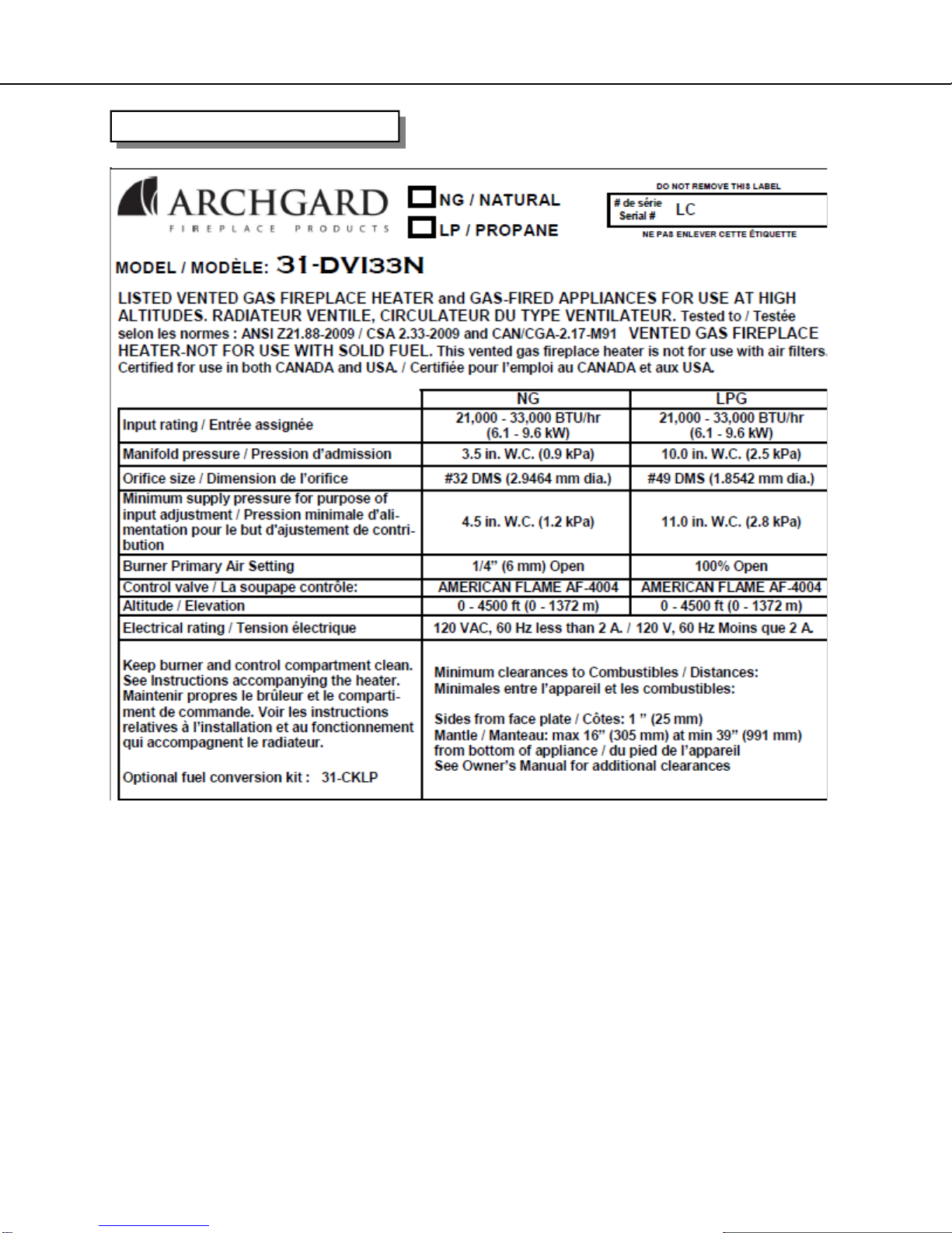
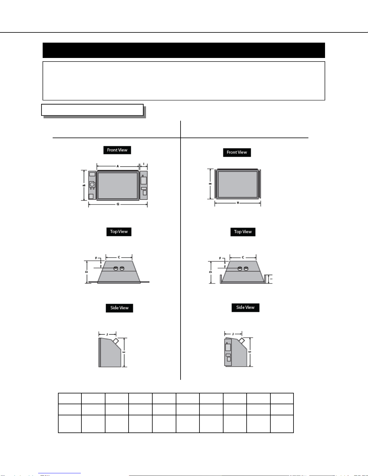
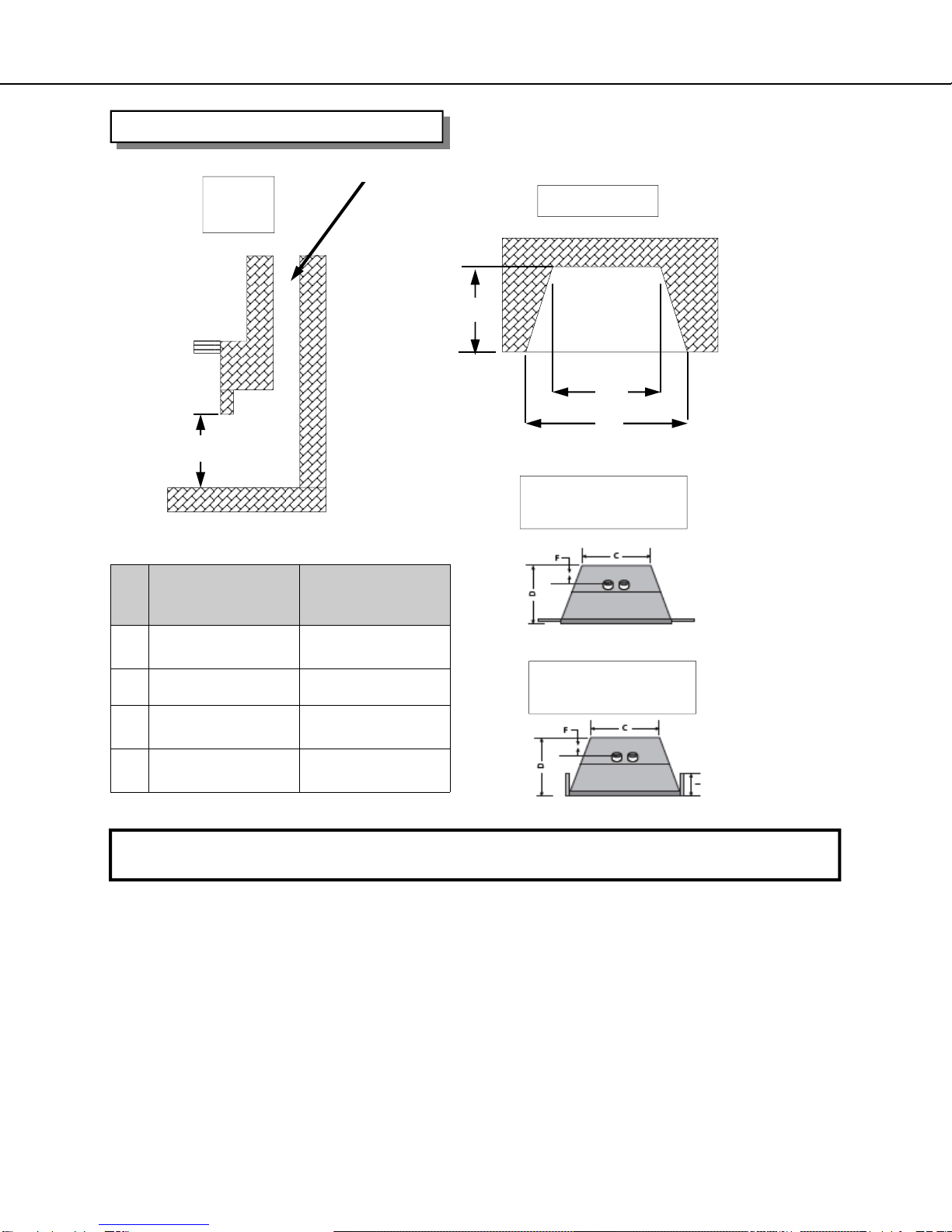
Archgard 31-DVI33N Owner's manual

200-0031
July 2011
31-DVI33N
Gas Fired Vented Room
Heater (Direct Vent)
USERS’ INSTALLATION
OPERATION and
MAINTENANCE MANUAL
7116 Beatty Dr
Mission, BC V2V 6B4
Canada
INSTALLER: Leave this manual with the appliance.
CONSUMER: Retain this manual for future reference.
Do not store or use gasoline or other flammable
vapors and liquids in the vicinity of this or any
other appliance.
WHAT TO DO IF YOU SMELL GAS:
∗ Do not try to light any appliance.
∗ Do not touch any electrical switch; do not use
any phone in your building.
∗ Immediately call your gas supplier from a
neighbor’s phone. Follow the gas supplier’s
instructions.
∗ If you cannot reach your gas supplier, call the
fire department.
Installation and service must be performed by a
qualified installer, service agency or the gas
supplier.
This appliance may be installed in an
aftermarket permanently located,
manufactured home (USA only) or mobile
home, where not prohibited by local codes.
This appliance is only for use with the type
of gas indicated on the rating plate. This
appliance is not convertible for use with
other gases, unless a certified kit is used.
*Conversion kit required for Propane use
WARNING: If the information in this manual is
not followed exactly, a fire or explosion may
result causing property damage, personal
injury or loss of life.
Tested and listed by
LABTEST Certification Inc
Richmond, British Columbia
ANSI Z21.88-2009/CSA 2.33-2009


INTRODUCTION
Congratulations on choosing an Archgard Gas Fireplace!
The 31-DVI33N is one of the most advanced Direct Vent Insert heaters available today. It is
solidly designed using the latest technology and manufactured to the highest quality. It is our
aim to provide you with an appliance for many trouble-free years of reliable service.
Some of the many features of your 31-DVI33N are:
• Heater Classification The 31-DVI33N is classified as a heating appliance.
Therefore, it uses Direct Vent safety technology and it is
suitable for continuously operated zone heating.
• High Efficiency The 31-DVI33N has one of the highest efficiencies of any
Direct Vent gas insert, which means that it is less expensive
to operate.
• Adjustable Fan Speed Each 31-DVI33N comes complete with a heat-activated
circulation fan with a fully adjustable speed control.
• Adjustable Flame The flame aesthetics and heat output can be adjusted to suit
the owner’s liking and heating needs.
• Solid Construction The 31-DVI33N is mainly constructed of 16 and 18 gauge
galvanized and aluminized coated steel for long life and
durability.
• Optional Accessories Check with your Authorized Archgard Dealer for a full
complement of decorative accessories to suit your home’s
décor and your tastes.
• Electronic Control System The 31-DVI33N uses a gas control valve that is operated by a
Supreme Multifunction Remote Control. It can be used as
either an Intermittent Pilot or Standing Pilot system.
Fireplace Model Number 31-DVI33N
Fireplace Serial Number
Date of Installation
Type of Gas Used by the Fireplace
Dealer’s Name

TABLE OF CONTENTS
Caution and Safety Instructions 5
Appliance Certification, Installation Codes and Specifications 6
Rating Plate 7
Control Panel Locations 8
Appliance Dimensions and Minimum Requirements for Fireplace Dimensions 9
Factory Built (metal) Fireplace Requirements 10
Clearance to Combustibles 11
Gas Connections 12
Conversion Kit Instructions 13-14
Appliance Description, Leveling the Appliance and Electrical Requirements 15
Venting Instructions 16-17
Surround Installation and Rocker Switch Wiring 18
Log Placement 19-24
Final Installation Check and Initial Operation 25
First Fire and Lighting Instructions (CAUTION) 26
Lighting Instructions on Rating Plate 27
Remote Control Setup and Operation 28-32
Glass Door Removal / If Your Glass Should Break 33
Maintenance and Cleaning the Appliance 34
Servicing Under Warranty and Adjusting Primary Air 35
Checking Inlet/Outlet gas pressures, Adjusting Pilot and Convertible Pilot Orifice 36
Replacing Convection Blower 37
Wiring Schematic 38
Fiber Logs 39
Warranty 40
Frequently Asked Questions 41
Notes 43-44
Warranty Registration Card 45
Replacement Parts List 42

31-DVI33N 5
Due to high temperatures, the appliance should be located out of traffic and away from furniture
and draperies.
Children and adults should be alerted to the hazards of high surface temperature and stay
away to avoid burns or clothing ignition.
Young children should be carefully supervised when they are in the same room as the
appliance. Toddlers, young children and others may be susceptible to accidental contact
burns. A physical barrier is recommended if there are at risk individuals in the house. To
restrict access to a fireplace or stove, install an adjustable safety gate to keep toddlers, young
children and other at risk individuals out of the room and away from hot surfaces.
Clothing or other flammable material should not be placed on or near the appliance.
Do not operate with cracked or broken glass. Be careful not to strike or slam the glass.
Any safety screen or guard removed for servicing an appliance must be replaced prior to
operating.
Installation and Repair should be done by a qualified service person. The appliance should be
inspected before use and at least annually by a professional service person. More frequent
cleaning may be required due to excessive lint from carpeting, bedding materials, etc. It is
imperative that the control compartments, burners and circulating air passageways of the
appliance are kept clean.
Do not use this appliance if any part has been under water. Immediately call a qualified service
technician to inspect the appliance and to replace any part of the control system and any gas
control which has been under water.
CAUTION
FOR YOUR SAFETY - Do not install or operate your Archgard 31-DVI33N without reading and
understanding this manual. Any installation or operational deviation from this instruction manual
voids the Archgard Industries Warranty and may prove hazardous.
This appliance must be installed by a qualified gas installer and the installation must conform to
the installation codes.
Provide adequate clearance around air openings.
Never obstruct front openings.
Provide adequate clearances for proper operation and servicing of the appliance.
This appliance must be properly connected to an approved venting system and must not be
connected to a chimney flue serving a separate solid fuel burning appliance.
Must provide adequate clearance around the intake and exhaust openings
SAFETY

31-DVI33N 6
This appliance was listed by LABTEST Certification Inc to the following USA and Canadian gas
appliance standards.
- ANSI Z21.88-2009/CSA 2.33-2009 Vented Gas Fireplace Heaters
- CAN/CGA-2.17-M91, Gas-Fired Appliances for Use at High Altitudes
-CSA P.4.1-09 testing method for measuring annual fireplace efficiency.
The listing label is attached to the appliance on the bottom right side of the appliance.
A copy is shown on page
APPLIANCE CERTIFICATION
INSTALLATION CODES
This appliance must be installed by a qualified gas appliance installer. The installation must
conform with the local codes or, in the absence of local codes, with the current National Fuel
Gas Code ANSI Z223.1/ NFPA 54 in the US, or Installation Code CAN/CGA-B149.1 in
Canada. Electrical connections and grounding must conform with local code, or current
National Electrical code ANSI/NFPA No. 70-1987 in the US, and in Canada the current
Canadian Electrical Code CSA C22.1.
A manufactured home (USA only) or mobile home OEM installation must conform with the
Manufactured Home Construction and Safety Standard, Title 24CFR, Part 3280, or, when such
a standard is not applicable, the Standard for manufactured Home Installations, ANSI/
NCSBCS A225.1 or Standard for Gas Equipped Recreational vehicles and Mobile Housing,
CSA Z240.4
SPECIFICATIONS
Natural Gas (NG) Propane (LP)
Manifold Pressure 3.5 in. W.C. (0.9 kPa) 10.0 in. W.C. (2.5 kPa)
Min. Supply Pressure
Max Supply Pressure 4.5 in. W.C. (1.2 kPa)
14.0 in. W.C. (3.5 kPa) 11.0 in. W.C. (2.8 kPa)
14.0 in. W.C. (3.5 kPa)
Orifice Size #32 DMS (2.82 mm dia) #49 DMS (1.72 mm dia)
Nominal Input Rating 21,000 - 33,000 BTU/hr (6.1- 9.6kW) 21,000 - 33,000 BTU/hr (6.1 -9.6kW)
Electrical Rating 120 VAC, 60Hz less than 2 A. / 120 VAC, 60Hz less than 2 A. /
Gas Control American Flame AF 4004 American Flame AF-4004
Altitude 0 - 4,500 ft. (0 - 1372 M) 0 - 4,500 ft. (0 - 1372 M)
Primary Air Opening 1/4” (6 mm) OPEN FULLY OPEN
HIGH ALTITUDE INSTALLATION
When installing this appliance beyond 4500 ft. (1372 M) above sea level, the appliance must
be properly de-rated and installed according to local codes, in the absence of local codes, with
the current National Fuel Gas Code, ANSI Z223.1/ NFPA 54, in the US or Installation Code,
CAN/CGA-B149, in Canada.

31-DVI33N 7
RATING PLATE

31-DVI33N 8
APPLIANCE DIMENSIONS
“Controls Out” Configuration “Controls In” Configuration
A B C D E F G H I J
30” 20/1/4” 18-3/4” 16” 20” 2-1/2” 41-3/4” 33” 7” 12”
762
mm 514
mm 476
mm 406
mm 508
mm 63
mm 1060
mm 838
mm 178
mm 305
mm
The control panels can be mounted in the following different ways. They are shipped in the “Controls In” configu-
ration. They can be moved to the “Controls Out” configuration by removing the two mounting screw on each side
and swinging the panels out and replacing the screws. They can also be disconnected and placed remotely within
the limits of the gas connections and electrical wiring making sure to place them away from any heat source over
150 degrees Fahrenheit or 65 degrees Celsius
CONTROL PANEL LOCATIONS

31-DVI33N 9
MINIMUM FIREPLACE DIMENSIONS
J
SIDE
VIEW TOP VIEW
L
M
K
DIMENSIONS
“Controls Out”
J 20-1/4” (514 mm)
K 14” (356 mm)
L 19” (483 mm)
M 30” (762 mm)
DIMENSIONS
“Controls In”
20-1/4” (514 mm)
15 1/2” (394 mm)
19” (483 mm)
33 1/2” (851)
WARNING: Failure to position the parts in accordance with these diagrams or failure to use only parts
specifically approved with this appliance may result in property damage or personal injury.
The installer must mechanically attach the marking supplied with the gas fireplace insert to the inside of the firebox of
the fireplace into which the gas fireplace insert is installed.
Cutting of any sheet-metal parts of the fireplace, in which the gas fireplace insert is to be installed, is prohibited.
If the factory-built fireplace has no gas access hole (s) provided, an access hole of 1 1/2” (38.1 mm) or less may be
drilled through the lower sides or bottom of the firebox in a proper workmanship-like manner. This access hole must
be plugged with non-combustible insulation after the gas supply line has been installed.
The fireplace flue damper can be fully blocked open or removed for installation of the gas fireplace insert.
The fireplace and fireplace chimney must be clean and in good working order and constructed of non-combustible
materials. The chimney cleanouts must fit properly.
Refractory, glass doors, screen rails, screen mesh and log grates can be removed from the fireplace before installing
the gas fireplace insert.
Smoke shelves and baffles may be removed if attached by mechanical fasteners. Trim panels must not seal ventila-
tion openings in the fireplace.
Min flue size required 4” (102) x 7” (178)
TOP VIEW
CONTROLS IN
TOP VIEW
CONTROLS OUT

31-DVI33N 10
Factory –Built (metal) Wood-Burning Fireplace Requirements
Any parts that are removed must be saved and re-installed if the insert is ever removed.
The damper (A) and grate (B) must be removed
The smoke shelf ©, internal baffles (D), screen ( E), masonry lining or refractory (G and I), and
metal or glass doors (F) may be removed.
The fireplace must be permanently marked to indicate that it has been altered and is no longer
suitable for burning any fuel unless the removed parts are reinstalled. Cutting out of any metal
parts is prohibited, except the metal floor (J) as specified.
The metal floor of the firebox may be removed only if the following is
strictly adhered to.
The metal floor (J) may be removed to allow additional room for installation of the in-
sert. If the floor is removed the insert must be placed directly on the metal base of the
metal fireplace. Under no circumstance can it be placed directly on a combustible
material.
Any hearth extending out in front of the insert must not have any portion above 7” be-
low the bottom of the unit made from combustible materials. This includes any type of
framing underneath a non-combustible material such as tile, marble or stone. Any ma-
terial below 7” can be combustible.

31-DVI33N 11
CLEARANCES TO COMBUSTIBLES
TOP VIEW
SIDE VIEW
Clearances to Faceplate
8” (204 mm)
Sidewalls or Mantle Supports
CAUTION: This appliance is designed for use in any masonry or factory-built, wood-burning
fireplace. It cannot be enclosed by combustible material and used as a built-in gas fireplace.
WARNING: Failure to position the parts in accordance with these diagrams or failure to use
only parts specifically approved with this appliance may result in property damage or personal
injury or loss of life.
Combustible mantle allowed in
shaded area. Mantle extension
maybe increased 1” (25.4 mm) for
each additional 1” (25.4 mm)
increase in clearance height.
Example: If using a 5” (127 mm)
reduce minimum height to
31” (788 mm).
If using a 4” (102 mm) reduce
minimum height to 30” (762 mm)
12” (305mm)
Minimum Height
From Bottom of
Appliance: 38”
(966 mm) with a
12”(305 mm) mantel.
Note:
If existing wood fire-
place hearth protection
is removed it must be
replaced by a non-
combustible hearth
protection extending
16” (406 mm) from the
front of the fireplace
insert or have a mini-
mum 7” (178 mm)
clearance below the
bottom of the inserts.
Minimum 8” (204 mm)
clearance is required from the
glass door frame to a sidewall
or mantle support.
7”
Minimum clear-
ance to combus-
tibles framing

31-DVI33N 12
Before connecting the appliance to the gas supply line, double check that the appliance you
have purchased is designed for the gas type you are using. The gas type markings are located
on the certification label and also on the appliance’s gas valve.
Adequate clearance for proper installation and checking of the gas connections must be
provided. All gas connections must be checked for gas leaks.
GAS CONNECTIONS
Have your gas supplier or a qualified gas fitter run a gas supply line into the fireplace. The line
must be properly sized and fitted according to the installation codes. Immediately upstream of the
supply connection, the fitter shall provide an accessible manual shut-off valve. When connecting
the supply line to the gas valve, the installer shall brace the gas valve to ensure that the gas valve
is not moved from its bracket. If the valve is not braced when the supply line is connected, the
valve may be moved and cause a “break” in the main burner supply line. Such damage is not
covered by the manufacturer’s warranty.
CAUTION: The appliance and its individual shutoff valve must be disconnected from the gas
supply piping system during any pressure-testing of that system at test pressures in excess of 1/2
psig (3.5 kPa). The appliance must be isolated from the gas supply piping system by closing its
individual manual shutoff valve during any pressure-testing of the gas supply piping system at
test pressures equal to or less than 1/2 psig (3.5 kPa). Failure to do so will damage the
appliance’s gas valve. Such damage is not covered by the manufacturer’s warranty.
Natural Gas Pressure Settings:
The inlet supply or line pressure must be a minimum of 4.5” W.C. (1.2 kPa) and a maximum of
14” W.C. (3.5 kPa). The orifice is a #32 DMS (2.95 mm) drill size.
ELEVATION INPUT RATING
0-4500 ft (0-1372 M) 33,000 BTU/hr (9.6 kW)
4500 ft (1372 M) and above. 33,000 BTU/hr (9.6 kW) less 4% per 1000 ft. (305 M)
Please contact your local distributor for the appropriate orifice size you require.
Propane Pressure Settings:
The inlet supply or line pressure must be a minimum of 11” W.C. (2.8 kPa) and a maximum of 14”
W.C. (3.5 kPa). The orifice is a #49 DMS (1.85 mm) drill size.
ELEVATION INPUT RATING
0-4500 ft. (0-1372 M) 33,000 BTU/hr (9.6 kW)
4500 ft. (1372 M) and above. 33,000 BTU/hr (9.6 kW) less 4% per 1000 ft. (305 M)
Please contact your local distributor for the appropriate orifice size you require.
NOTE: THE INPUT RATING SHOULD ALWAYS BE CHECKED WHEN FIRST RUNNING THIS
APPLIANCE. To do this, reduce the background flow rate, time the meter, light the fireplace and
take another reading after 15 minutes of operation. Check with your gas supplier for the gas BTU
content at your elevation. Input is the rate of flow multiplied by the heating value of the gas (cubic
feet/hour x BTU per cubic feet). Adjust the manifold pressure so that the unit does not operate
above the rated input.

31-DVI33N 13
CONVERSION KIT INSTRUCTIONS
IMPORTANT: This fireplace is Natural gas ready. If converting to LP gas, follow instructions below
WARNING: This conversion kit shall be installed by a qualified service agency in accordance with the
manufacturers instructions and all applicable codes and requirements of the authority having jurisdiction. If
the information in these instructions is not followed exactly, a fire, explosion or productions of carbon mon-
oxide may result, causing property damage, personal injury or loss of life. The qualified service agency is
responsible for proper installation of this kit. The installation is not proper and complete until operation of
the converted appliance is checked as specified in the instructions supplied with the kit. Refer to appliance
owner’s manual or product data plate for proper inlet and manifold pressure adjustments and orifice sizing.
IMPORTANT: For high altitude installations above 4500 ft (1372 meters), consult local gas distributor or
the authority having jurisdiction for proper de-rating methods.
KIT NUMBERS: “31-CKLP” for LP gas and “31-CKNG” for Natural Gas
KIT INCLUDES:
• 1– gas conversion label
• 1-burner orifice (#49 for LP) (#32 for Natural Gas)
• 1-gas type label
• 1-Low limit screw (#52)
PREPARE THE FIREPLACE
Remove the surround, glass frame assembly, logs and brick (if applicable).
Remove the burner cover by removing the two screws at the back and lifting straight up.
Remove burner by removing the screw on each side of the burner and sliding the burner to the right until it lifts
straight up.
Remove the burner orifice using a 1/2” wrench. Replace with the orifice supplied with the conversion kit. Use a
small amount of pipe sealant.
Next use a 7/16” wrench and loosen the pilot hood 1/4 turn. Slide the tab at the bottom of the orifice hood all the
way so the red side with the hole in it is showing. Tighten the pilot hood back up so that it is lined up with the
two probes on both sides of the pilot assembly.
Re-install the burner, brick, logs, embers and door.
CONVERT THE GAS CONTROL VALVE AND REMOTE
Unscrew the threaded regulator cap on the control valve.
Press down on pressure regulator tube and rotate 90 degrees. The tube should only come up half way for LP after
released and the line should point to LP. Screw cap back on.
Remove Low limit screw (brass screw in front and to the right of the valve motor) and replace with the new
screw supplied in the conversion kit.
WARNING: SHUT OFF GAS SUPPLY AND ELECTRICAL POWER TO FIREPLACE
SHUT OFF GAS SUPPLY BEFORE DISCONNECTING ELECTRICAL POWER

31-DVI33N 14
CONVERT THE GAS CONTROL VALVE, MAIN CONTROL MODULE AND REMOTE
GAS CONTROL VALVE:
Unscrew the threaded regulator cap on the control valve.
Press down on pressure regulator tube and rotate 90 degrees. The tube should only come up half way for
LP after released and the line should point to LP. Screw cap back on.
Remove Low limit screw (brass screw in front and to the right of the valve motor) and replace with the
new screw supplied in the conversion kit.
MAIN CONTROL MODULE:
Press and hold the learn button on the main control module for 20 seconds (on top next to the cable con-
nection). A beep (1 second for LP and 3 seconds for natural gas) will be heard letting you know the pro-
cedure has been completed.
REMOTE:
Press and hold the Flame Rear and Prog/Time buttons on the remote simultaneously for 5 seconds. The
Temperature will start to flash. Push the set button until the NG or LP on the lower left of the display is
flashing. Push the up or down button until the proper fuel type is displayed. Wait 20 seconds and the dis-
play will stop flashing and the remote is now set for the desired fuel type.
COMPLETE THE CONVERSION
Turn on the gas and electrical supplies.
Turn on the fireplace so the burner is on
Check for leaks at all connections.
Test inlet pressure. Visually check pilot flame. Flame should envelope top of the flame sensor and extend for-
ward onto the burner. To adjust pilot turn the pilot adjustment screw on the control valve clockwise to decrease
or counter clockwise to increase pilot flame.
Turn fireplace off
Affix gas type label to the rating plate label. (Bottom right side, under the door frame of insert on pull chain)
Complete the conversion label and affix to valve assembly plate.
CONVERSION KIT INSTRUCTIONS CONT.

31-DVI33N 15
LEVELING THE 31-DVI33N
Before placing the appliance into the fireplace, check the hearth of the fireplace to see if it is
level with the front of the fireplace. If it is not, measure the depth of the hearth. Loosen the
three screws of the leveling “L” bracket at the back of the appliance. Lower it to the
measurement obtained and tighten the screws.
APPLIANCE DESCRIPTION
ELECTRICAL CONNECTIONS
The 31-DVI33N comes complete with a temperature-activated fan and rheostat installed and
wired to a three-prong (grounding) plug for your protection against shock hazard and should be
plugged in directly into a properly grounded three-prong receptacle. Do not cut or remove the
grounding prong from this plug.
NOTE: This appliance, when installed, must be electrically grounded in accordance with local
codes or, in the absence of local codes, with the National Electrical Code, ANSI / NFPA 70,
or the Canadian Electrical code, CSA C22.1.
FRONT VIEW
Ceramic
Glass with
standard
black door
frame
Surround
“Faceplate”
TOP VIEW
On/Off
Rocker
Switch
Fresh Air IntakeExhaust

31-DVI33N 16
The 31-DVI33N
requires two flexible
gas flue liners:
Flue Collar (inlet) -
3” (76 mm) diameter
Flue Collar (outlet) -
3” (76 mm) diameter
Caution: Only two 3” (76 mm) “FLEX-MASTER” Model GA gas flex vent liners (or approved equivalent)
and a vent terminal is approved for use with this appliance.
Approved vent terminals are:
• Archgard terminal. Part # 999-INS-TK
• Simpsons Dura-Vent terminal. Part # 980, 923GK (adaptor with flashing) or 991 (high wind
cap). If you are using “Dura-Vent” vertical termination cap, follow the instructions provided
with the “Dura-Vent” cap.
NO OTHER VENTING SYSTEM OR COMPONENTS MAY BE USED.
This appliance is designed to attach to two 3” (76 mm) co-linear aluminum flex gas liners running the full
length of the chimney. The flue length must be a minimum of 8’ (2.44 M) and a maximum of 40’ (12.2 M)
(The exhaust vent restrictor provided with this appliance must only be used by installing it onto
the front of the baffle on natural gas units with vent heights over 18’ (5.4 M). Also refer to the follow-
ing page for details. The minimum flue size is 4” x7” (100 mm X 178 mm).
Masonry chimneys may take various contours which the flexible liner will accommodate, however, keep
the flexible liner as straight as possible, avoiding unnecessary bending but at all times keep a minimum of
3” (76 mm) inside bend radius.
The Air Intake Flex Liner must be connected to the inlet air collars of the termination cap and the appli-
ance. The Exhaust Flex Liner must be connected to the exhaust collars of the termination cap and the
appliance. (DO NOT MIX-UP THESE CONNECTIONS).
The Air intake and Exhaust connections are marked on the gas appliance. See Fig. 1.
CAUTION: To ensure that the venting path is not accidentally obstructed or punctured, the
damper of the host fireplace must be permanently disabled by either complete removal of the
damper, or welding it in its “open” position. Temporarily disabling the damper with braces,
VENTING INSTRUCTIONS
WARNING: Operation of this heater when not connected to a properly installed and main-
tained venting system can result in carbon monoxide (CO) poisoning and possible death.
The appliance must not be connected to a chimney flue serving a separate solid fuel
burning appliance.
Exhaust Fresh Air Intake
The 31-DVI33N showing the Fresh Air Intake and Exhaust locations.
These connections are labeled for you.
Fig. 1

31-DVI33N 17
Instructions for use with Archgard vertical termination cap. Part # 999-INS-TK
Install the termination cap being sure to provide sufficient space (around and on top) so as not to
impede the flow of air, both into and out of the cap. This cap is only to be used for non combusti-
ble installations. Do not recess into the top of the chimney.
1. Mark each end of one liner with “Air Intake”.
2. Mark each end of the second liner with “Exhaust”.
3. Pull the liner through the chimney.
4. Install the flashing. Do Not bend or cut the flashing in any way.
5. Seal and attach the liner marked “Air Intake” to the vent terminal pipe marked “Air Intake” with the collar
clamp provided.
6. Seal and attach the liner marked “Exhaust” to the vent terminal pipe marked “Exhaust” with the collar clamp
provided.
7. Seal and attach the end of the flex marked “Air Intake” to the collar marked “Air Intake” on the appliance
with the collar clamp provided with the unit.
8. Install exhaust vent restrictors provided with the unit on Natural Gas appliances only. . Seal and attach
the end of the flex marked “Exhaust” to the collar marked “Exhaust” on the appliance.
9. Caulk all joints using a high temperature sealant such as milpac. DO NOT USE SILICONE SEALANTS. Use
of silicon sealants voids the warranty of the pilot assembly.
NOTE: The vertical termination cap must be sealed to the liner with suitable high temperature sealant and with the
hose clamps fasteners provided. The liners must form a complete connection from the appliance flue collars to the
vertical termination cap.
VENTING INSTRUCTIONS 999-INS-TK
The minimum flue (chimney) size required to run the two 3” (76 mm) is 4” x7” (100 mm X 178 mm)
Front view of
DV Insert
Exhaust
Collar
Exhaust
Air Intake
Collar
3” (76 mm)
Flex Liner Fresh Air
Intake
Min. vent height 10’(2.54 M)
Max. vent height 40’ (12.2 M)
Vertical Termination cap
Part # 999-INS-TK
Place Vent Restrictor
in the position shown
when operating with
NATURAL GAS with a
vent over 18’ (5.5 Me-
ters)
Firebox baffle with
restrictor
Firebox baffle with-
out restrictor

31-DVI33N 18
SURROUND INSTALLATION
Surround options available are dependent upon the control panel configuration. (See Control
Panel Locations regarding configuration.) Shallow surround options are not available on a unit
with ‘Controls Out’ configuration.
Make sure the gas and electrical lines are properly connected to the appliance. Slide the unit
into the fireplace and slide the excess flue liner material back onto the chimney. Before the ap-
pliance is fully recessed into the fireplace, attach the surround onto the appliance.
Attach the surround to the appliance at the locations shown by lining up the tabs on the sur-
round with the slots on the unit. Make sure the surround drops down and fully engages. Then
finish with the wiring connection to the on/off switch on the side of the trim. Now fully “seat” the
unit into its final position.
Surround Mounting slots
Surround Mounting tabs

31-DVI33N 19
LOG PLACEMENT
WARNING:
Failure to position the parts in accordance with these diagrams or failure to use only parts
specifically approved with this appliance may result in property damage or personal injury.
The Archgard pan burner bed and fiber logs are designed to give a realistic fire package, and cre-
ated to look the same as the day they were originally installed. Care must be given when first in-
stalling the logs, and if removed for servicing, as they can be damaged or broken if not handled
properly.
After opening the log set package, inspect the logs to ensure that no damage has occurred inside
the package. Please report any damage immediately to your Authorized Archgard Dealer.
Gas and vent connection must be made before installing the embers and logs on the pan burner.
NOTE: Improper placement of logs and embers may cause sooting on the internal parts and glass
and will not be covered under warranty. Do not use broken or damaged logs.
Locate the embers and logs and place them on their prospective locations. Refer to the pictured
instructions on the following pages that will show how to place all seven (7) logs. Pins and holes
must be aligned with logs and burner.
IMPORTANT: Embers should be placed so as not to block burner ports. Separate the material
and spread around the pan as shown below.
NOTE: Installing the fiber logs in any other position other than shown will result in flame
impingement causing sooting of the logs, brick liner and ceramic glass viewing area.
Locator Pins and Embers Shown
LOCATOR PINS
LOG RESTS

31-DVI33N 20
Logs
LOG 1 LOG 7
LOG 4
LOG 2
LOG 6LOG 3
LOG 5
Table of contents
Other Archgard Gas Heater manuals

Archgard
Archgard Optima 40 Owner's manual

Archgard
Archgard Optima 45-1 Owner's manual

Archgard
Archgard Optima 45 - 3 Maintenance and service guide

Archgard
Archgard Optima Owner's manual

Archgard
Archgard 31-DVIM33C Owner's manual

Archgard
Archgard Optima 72-DVT30N Owner's manual

Archgard
Archgard 31-DVIE33C Owner's manual

Archgard
Archgard 3600-DVTR24N-2 Owner's manual
Popular Gas Heater manuals by other brands

Lennox
Lennox MERIT PLUS SERIES Homeowner's care and operation instructions

TriangleTube
TriangleTube CHALLENGER CC 85 instructions

StyleWell
StyleWell SP5822 Use and care guide

HearthStone
HearthStone Tudor Owner's manual & installation guide

Majestic
Majestic 18NB Installation and operating instructions

MW TOOLS
MW TOOLS WG450 manual