ARCHGARD FIREPLACE PRODUCTS
7116 Beatty Drive
Mission, BC V2V 6B4 Canada 200-0038-01
August 18, 2020
English and French Installation Manuals available through
your local dealer or visit our website at:
www.archgard.com
Les manuels d'installation en anglais et en français son
disponibles chez votre détaillant local ou en visitant notre
site web: www.archgard.com
INSTALLER:
LEAVE THIS MANUAL WITH THE APPLIANCE.
CONSUMER:
RETAIN THIS MANUAL FOR FUTURE REFERENCE.
INSTALLATION MANUAL
After removing the parts from packaging, inspect them to ensure
that no damage has occurred. Please report any damage
immediately to your authorized Archgard dealer.
Only kits supplied by the manufacturer may be used.
MODELS:
999-IHT-440 999-IHT-12B2B
999-IHT-41212 999-IHT-12B2W
999-IHT-44012 999-IHT-4FS
999-IHT-40B1B 999-IHT-4V10
999-IHT-40B1W 999-IHT-4V25
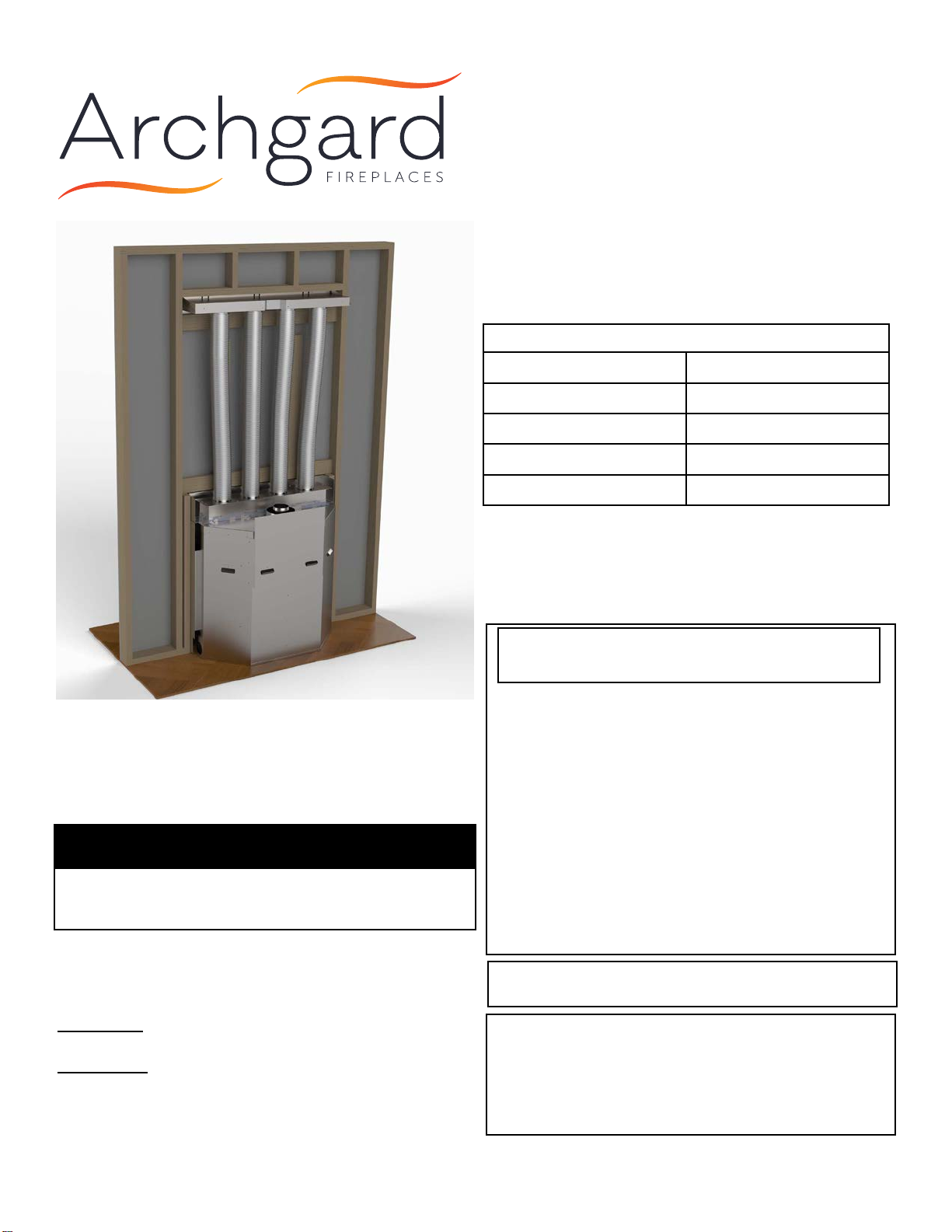
I.H.E.A.T. Advantage
Intelligent Heat Exchange
and Air Transfer
Do not store or use gasoline or other ammable vapors or
liquids in the vicinity of this or any other appliance.
WHAT TO DO IF YOU SMELL GAS:
• Do not try to light any appliance
• Do not touch any electrical switch; do not use any phone in
your building
• Immediately call your gas supplier from a neighbors phone.
• Follow the gas suppliers instructions
• If you can not reach your gas supplier, call the re
department
Installation and service must be performed by a qualied
installer, service agency or the gas supplier.
WARNING: If the information in this manual is not followed
exactly, a re or explosion may result causing property
damage, personal injury or loss of life.
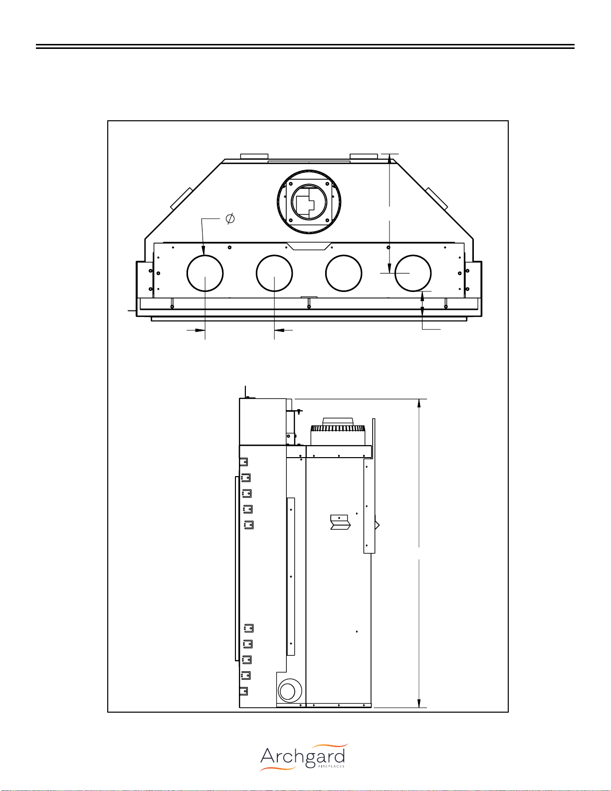
For installation on 345-DVTE31LN-1
(see the Installation, Operation, and
Maintenance Manual included with the
replace
IMPORTANT
Please review and understand the information in this manual in full
PRIOR to beginning your installation.