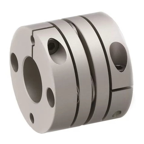
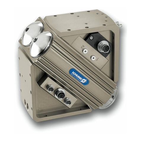
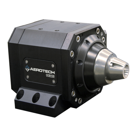
Miki Pulley Starflex ALS Series User manual

TRS-ALS-002-01/MD-000067150A
-1-
Miki Pulley Starflex Coupling
ALS –Y / R / B Model
Operation Manual
1. Safety Precautions
1-1 Precaution against mechanical hazards . . . . . . . . . . . . . . . . . . . . . . . . . P. 2
1-2 Precaution for safe assembly . . . . . . . . . . . . . . . . . . . . . . . . . . . . . . . . . . P. 3
1-3 Precaution for safe operation . . . . . . . . . . . . . . . . . . . . . . . . . . . . . . . . . . P. 3 - 4
1-4 Precaution for safe maintenance and service . . . . . . . . . . . . . . . . . . . . . P. 4
1-5 Precaution for safe disposal . . . . . . . . . . . . . . . . . . . . . . . . . . . . . . . . . . . P. 5
2. Product Information
2-1 Unpacking the product . . . . . . . . . . . . . . . . . . . . . . . . . . . . . . . . . . . . . . P. 5
2-2 Structure . . . . . . . . . . . . . . . . . . . . . . . . . . . . . . . . . . . . . . . . . . . . . . . . . . . P. 5
2-3 Dimensions . . . . . . . . . . . . . . . . . . . . . . . . . . . . . . . . . . . . . . . . . . . . . . . . . P. 5
3. Installation Procedures
3-1 Handling Precautions. . . . . . . . . . . . . . . . . . . . . . . . . . . . . . . . . . . . . . . . . P. 6
3-2 Operating environment . . . . . . . . . . . . . . . . . . . . . . . . . . . . . . . . . . . . . . P. 6
3-3 Installation procedures Key/Set Screw style hubs . . . . . . . . . . . . . . . . P. 6 - 7
3-3 Tightening torque for set screws . . . . . . . . . . . . . . . . . . . . . . . . . . . . . . . P. 6
3-3 Standard specifications for the Key/set screw style hubs . . . . . . . . . . . P. 7
3-4 Installation procedures Clamp style hubs . . . . . . . . . . . . . . . . . . . . . . . P. 8 - 9
3-4 Tightening torque for clamp bolts . . . . . . . . . . . . . . . . . . . . . . . . . . . . . P. 8
3-4 Standard specifications for the Clamp style hubs . . . . . . . . . . . . . . . . . . P. 8 - 9
3-4 Standard bore diameter and bore diameter by limited allowable torque P. 9
Please read this Instruction Manual carefully before
using the Miki Pulley Starflex Coupling.
Forward this manual to the end-user for safe operation of coupling.

-2-
1. Safety Precautions
Read the operation manual and technical documents carefully before using this product. Failure to comply with
these instructions could result in serious injury or damage to equipment.
Safety precautions, in this manual, are labeled as "DANGER" or "CAUTION."
Before using this product in a device or machine where failure or malfunction can lead to a direct threat to life or
health (for example: nuclear power equipment, aerospace equipment, medical devices, transportation devices,
and safety devices) prior consideration must be given from Miki Pulley. Contact our authorized sales
representative.
This document must be given to the end user and should be kept for future reference. This manual’s contents
must always be observed to protect the user and others from danger, and preventing property damage when using
this product.
1-1 Precautions against mechanical hazards
Use safety shields or guards.
Contacting a moving part will cause injury. Use safety shields or guards to prevent
hazards. Provide a safety mechanism that halts the operation immediately when a safety
shield or guard is open.
Never use the product in a hazardous atmosphere that can cause ignition or
explosion.
Never use the product in an atmosphere of oil or flammable gas that can cause
ignition or explosion.
Provide a safety mechanism.
In the event of a product breakdown, the driven part can be completely separated
from the driving part. To prevent hazards, a safety mechanism should be in place.
DANGER:
Use safety guards
Danger of ignition
DANGER:
CAUTION:
Fields with this label may pose an imminent danger that could lead to
serious or even fatal injury, or other major incidents.
Fields with this label may cause personal injury or property damage if the
caution is not observed.
DANGER:
DANGER:
Mandatory

-3-
1-2 Precautions for safe assembly
Be sure to tighten all bolts and screws.
Improperly tightened bolts or screws can lead to product damage or impaired product
performance. Tighten the bolts and screws to our specified tightening torque.
Never turn on the machine during installation. Lock Out –Tag Out.
When installing the product, make sure that the main power of the machine is turned
off and can not be accidently turned on. If the driving part moves unexpectedly, personal
injury could result.
Do not exceed maximum permissible misalignment.
Attach the product to a machine within our specified "maximum permissible
misalignment." Failure to comply may cause injury, breakdown or machine damage.
Use Miki Pulley specified bolts and screws only.
Use Miki Pulley specified bolts and screws only. Failure to comply may cause injury,
breakdown or machine damage.
1-3 Precautions for safe operation
Do not exceed maximum RPM of unit.
Operating the product above the maximum speed can lead to product failure, damage
or an adverse influence on the machine. Observe the maximum speed.
Never touch the product while in operation.
Since the product contains rotating parts, touching the operating product will cause
injury. Never touch the product while in operation.
Prohibited
Prohibited
Prohibited
DANGER:
Mandatory
Never touch
DANGER:
Mandatory
CAUTION:
CAUTION:
DANGER:
DANGER:

-4-
Never use the product above the permissible torque.
Operating the product above the permissible torque can lead to product failure,
damage or an adverse influence on the machine. Never use the product above the
permissible torque.
If abnormal noises or vibrations occur, shut down the product immediately. Lock
Out -Tag Out Machine.
Unusual noises or vibrations may be a sign of abnormalities in the machine or product.
Problems left unsolved can damage the machine. Stop the operation immediately and
check the machine and product.
Never use the product in an environment that may have an adverse affect on the
product.
Use the product in a controlled environment. Do not expose to chemical sprays, strong
corrosives, extreme high or low temperatures. Failure to comply may cause injury,
breakdown or machine damage.
Never use the product with joint slippage. Fasten to shaft according to specified
tightening torques.
Slippage at the joint can generate heat during operation, damaging the product and
an adverse affect on the machine. Never use the product with joint slippage. Failure to
comply may cause injury, breakdown or machine damage.
1-4 Precautions for safe maintenance and service
Lock Out - Tag Out before beginning maintenance on machine.
Before starting any maintenance or service, be sure to turn off the main power to the
machine. Lock out -Tag Out machine to prevent accidents. Failure to comply may cause
injury.
Never disassemble the product.
Do not attempt to disassemble the product shipped as a complete assembly.
Unauthorized disassembly work can cause injury or damage the product.
Prohibited
CAUTION:
Prohibited
CAUTION:
Prohibited
Prohibited
Never disassemble
CAUTION:
DANGER:
Mandatory
CAUTION:
CAUTION:

-5-
1-5 Precautions for safe disposal
Keep away from infants and children.
To protect the environment, recycle where available.
2. Product Information
2-1 Unpacking the product
Carefully inspect the coupling upon receipt for damages during transit.
2-2 Structure
Key/set screw style hubs Clamp style hubs
[Figure 1] [Figure 2]
2-3 Dimensions Table 1
Model
ALS-014
ALS-020
ALS-030
ALS-040
ALS-055
ALS-065
ALS-080
ALS-095
ALS-105
L [mm]
22
30
35
66
78
90
114
126
140
L1,L2[mm]
7
10
11
25
30
35
45
50
56
Key/set screw style Clamp style
[Figure 3] [Figure 4]
DANGER:
CAUTION:
If there are any problems please contact the company where you purchased the product.
Hub
Element
Set screw
Element
Clamp hub
Clamp bolt

-6-
3. Installation Procedures
3-1 Handling Precautions
■ In transporting, handle the product carefully to avoid damaging the product.
■ Never handle the product in a way that excessive force is applied to the parts.
3-2 Operating environment
■ Do not use the product in a hot, humid, or dusty environments.
■ Do not use the product beyond the specified operating ambient temperature range. (-30℃to +80℃)
■ Do not use the product where it is exposed to corrosive gas, oil, or chemicals.
■ Do not use the product outdoors. The product is not corrosion resistant.
■ Do not use the product in highly dynamic applications such as high speed reversing.
3-3 Installation procedures
[Figure 5]
Key/set screw style
■ Before installing, make sure the main power switch to the equipment is in the off position to avoid operating the
motor by mistake and to ensure safety. Lock out –Tag Out procedures should be followed.
■ Remove the dust, dirt, and oil accumulated on the target shaft and coupling bores.
■ Install hub on shaft so that engagement is equal to dimensions L1and L2shown in Section 2-3, Table 1 and
figures 3 and 4.
■Be sure to use a torque wrench to tighten the set screws. Tighten to the set screw tightening torque indicated
below:
Tightening torque for set screws Table 2
Set Screw Size
M3
M4
M5
M6
M8
M10
Tightening torque [Nm]
0.7
1.7
3.6
6.0
14.5
28.0
Property Class 12.9
Black anodized
■To achieve maximum performance; align the shafts according to tables for set screw and clamp style hubs. The
misalignments shown are maximum values. Closer alignment at the time of initial installation is recommended
to maximize coupling life.
■Check the alignment at two points about 90 degrees away by applying a straight edge to the outer diameter
of the main body. The life of the element is significantly affected by the centering accuracy.
Parallel Angular Axial

-7-
Standard specifications for Key/set screw style hubs Table 3
Model
(Yellow)
Torque
Maximum
Speed
[min-1]
Misalignment
Nominal
[Nm]
Maximum
[Nm]
Parallel
[mm]
Angular
[°]
Axial
[mm]
Weight
[kg]
ALS-014-Y
1.2
2.4
34100
0.10
1
+0.6
0
0.007
ALS-020-Y
3
6
23800
0.15
1
+0.8
0
0.018
ALS-030-Y
7.5
15
15900
0.15
1
+1.0
0
0.047
ALS-040-Y
10
20
11900
0.10
1
+1.2
0
0.15
ALS-055-Y
35
70
8700
0.15
1
+1.4
0
0.35
ALS-065-Y
95
190
7400
0.15
1
+1.5
0
0.51
ALS-080-Y
190
325
6000
0.15
1
+1.8
0
1.01
ALS-095-Y
265
530
5000
0.15
1
+2.0
-0.5
1.5
ALS-105-Y
310
620
4500
0.20
1
+2.0
-0.9
2.1
Table 4
Model
(Red)
Torque
Maximum
Speed
[min-1]
Misalignment
Nominal
[Nm]
Maximum
[Nm]
Parallel
[mm]
Angular
[°]
Axial
[mm]
Weight
[kg]
ALS-014-R
2
4
34100
0.10
1
+0.6
0
0.007
ALS-020-R
5
10
23800
0.10
1
+0.8
0
0.018
ALS-030-R
12.5
25
15900
0.10
1
+1.0
0
0.047
ALS-040-R
17
34
11900
0.10
1
+1.2
0
0.15
ALS-055-R
60
120
8700
0.10
1
+1.4
0
0.35
ALS-065-R
160
320
7400
0.10
1
+1.5
0
0.51
ALS-080-R
325
650
6000
0.10
1
+1.8
0
1.01
ALS-095-R
450
900
5000
0.10
1
+2.0
-0.5
1.5
ALS-105-R
525
1050
4500
0.15
1
+2.0
-0.9
2.1
Table 5
Model
(Blue)
Torque
Maximum
Speed
[min-1]
Misalignment
Nominal
[Nm]
Maximum
[Nm]
Parallel
[mm]
Angular
[°]
Axial
[mm]
Weight
[kg]
ALS-030-B
12.5
25
15900
0.17
1
+1.0
-0.2
0.047
ALS-040-B
17
34
11900
0.20
1
+1.0
-0.5
0.15
ALS-055-B
60
120
8700
0.22
1
+1.4
-0.2
0.35
ALS-065-B
160
320
7400
0.25
1
+1.5
-0.6
0.51
ALS-080-B
325
650
6000
0.28
1
+1.8
-0.9
1.01
ALS-095-B
450
900
5000
0.32
1
+2.0
-0.5
1.5
ALS-105-B
525
1050
4500
0.36
1
+2.0
-0.09
2.1
Weights are at maximum bore diameter
Coupling specifications subject to change without notice

-8-
3.4 Installation procedures Clamp style hubs
■ The recommended dimensional tolerance of the target shaft is h7. (However, for a shaft diameter of φ35mm,
the tolerance is .)
■ Do not tighten the clamp bolt before inserting the shaft.
■ Wipe the rust, dust, oil and grease off the attachment shaft. Do not use clamp bolt with any oil or grease.
Molybdenum disulfide or extreme-pressure additives must be completely removed; as such additives
dramatically change the coefficient of friction.
■ Use only Miki Pulley clamp bolts.
■ After mounting the coupling, be sure to attach the safety shields or guards. Touching the coupling while it is
operating may result in an injury.
■ Be sure to use a torque wrench to tighten the clamp bolts. Tighten to the clamp bolt tightening torque indicated
in the table below:
Tightening torque for clamp bolts
Table 6
Model
ALS-014
ALS-020
ALS-030
ALS-040
ALS-055
ALS-065
ALS-080
Clamp bolt size
M2×6
M2. 5×8
M3×12
M5×16
M6×20
M8×25
M8×25
Tightening torque [Nm]
0.4
1.0
1.5
7.0
14.0
30.0
30.0
Property Class 12.9
Black anodized
Standard specifications for Clamp style hubs Table 7
Model
(Yellow)
Torque
Maximum
Speed
[min-1]
Misalignment
Nominal
[Nm]
Maximum
[Nm]
Parallel
[mm]
Angular
[°]
Axial
[mm]
Weight
[kg]
ALS-014-Y
1.2
2.4
10000
0.10
1
+0.6
0
0.007
ALS-020-Y
3
6
10000
0.15
1
+0.8
0
0.019
ALS-030-Y
7.5
15
10000
0.15
1
+1.0
0
0.045
ALS-040-Y
10
20
10000
0.10
1
+1.2
0
0.16
ALS-055-Y
35
70
7000
0.15
1
+1.4
0
0.34
ALS-065-Y
95
190
5900
0.15
1
+1.5
0
0.54
ALS-080-Y
190
325
4800
0.15
1
+1.8
0
1.00
Table 8
Model
(Red)
Torque
Maximum
Speed
[min-1]
Misalignment
Nominal
[Nm]
Maximum
[Nm]
Parallel
[mm]
Angular
[°]
Axial
[mm]
Weight
[kg]
ALS-014-R
2
4
10000
0.10
1
+0.6
0
0.007
ALS-020-R
5
10
10000
0.10
1
+0.8
0
0.019
ALS-030-R
12.5
25
10000
0.10
1
+1.0
0
0.045
ALS-040-R
17
34
10000
0.10
1
+1.2
0
0.16
ALS-055-R
60
120
7000
0.10
1
+1.4
0
0.34
ALS-065-R
160
320
5900
0.10
1
+1.5
0
0.54
ALS-080-R
325
650
4800
0.10
1
+1.8
0
1.00
+0.010
-0.025

-9-
Table 9
Model
(Blue)
Torque
Maximum
Speed
[min-1]
Misalignment
Nominal
[Nm]
Maximum
[Nm]
Parallel
[mm]
Angular
[°]
Axial
[mm]
Weight
[kg]
ALS-030-B
12.5
25
10000
0.17
1
+1.0
-0.2
0.043
ALS-040-B
17
34
10000
0.20
1
+1.2
-0.5
0.16
ALS-055-B
60
120
7000
0.22
1
+1.4
-0.2
0.34
ALS-065-B
160
320
5900
0.25
1
+1.5
-0.6
0.54
ALS-080-B
325
650
4800
0.28
1
+1.8
-0.9
1.00
Weights are at maximum bore diameter
Coupling specifications subject to change without notice
■ Torque values are limited in bore diameter. Review torque values by check the alignment at two points about 90
degrees away by applying a straight edge to the outer diameter of the main body. The life of the element is
significantly affected by the centering accuracy.
■ The specifications for special (non-catalog standard) models may differ from those given in the above table.
Check the specifications on the delivery specification sheet.
Standard bore diameter and bore diameter by limited allowable torque (Clamp style) Table 10
Model
Standard bore diameter [mm] and bore diameter by limited allowable torque [Nm]
3
4
5
6
6.35
7
8
10
11
12
14
15
16
18
19
20
22
24
25
28
ALS-014
0.31
0.42
0.54
0.65
ALS-020
1.2
1.6
2.1
2.2
2.6
3.0
ALS-030
2.0
2.2
3.4
4.7
5.4
6.0
7.4
ALS-040
8
16
23
31
34
34
34
ALS-055
38
41
48
51
54
61
67
71
80
Model
Standard bore diameter [mm] and bore diameter by limited allowable torque [Nm]
14
15
16
18
19
20
22
24
25
28
30
35
38
40
42
45
48
50
55
60
ALS-065
61
68
75
79
89
96
114
ALS-080
108
121
151
194
■ The bore diameters with values are available as standard bore diameters.
■ The allowable torque for the coupling is limited because of the clamp screw strength and bore size limitations.
Contact by email
Please contact us using the inquiry form and be aware that support for inquiries received on Saturdays,
Sundays, holidays, New Year's, and summer business holidays will be provided on the next business day.
Contact by phone
Japanese/English
Miki Pulley International Business Department
TEL +81-46-257-5109
This manual suits for next models
25
Table of contents
Other Miki Pulley Industrial Equipment manuals
