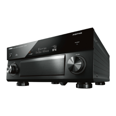
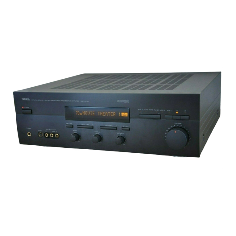
Yamaha DSP-AX620 User manual

AV AMPLIFIER
100763
This manual has been provided for the use of authorized YAMAHA Retailers and their service personnel.
It has been assumed that basic service procedures inherent to the industry, and more specifically YAMAHA Products, are already
known and understood by the users, and have therefore not been restated.
WARNING: Failure to follow appropriate service and safety procedures when servicing this product may result in personal
injury, destruction of expensive components, and failure of the product to perform as specified. For these
reasons, we advise all YAMAHA product owners that any service required should be performed by an
authorized YAMAHA Retailer or the appointed service representative.
IMPORTANT: The presentation or sale of this manual to any individual or firm does not constitute authorization, certification
or recognition of any applicable technical capabilities, or establish a principle-agent relationship of any
form.
The data provided is believed to be accurate and applicable to the unit(s) indicated on the cover. The research, engineering, and
service departments of YAMAHA are continually striving to improve YAMAHA products. Modifications are, therefore,
inevitable and specifications are subject to change without notice or obligation to retrofit. Should any discrepancy appear to exist,
please contact the distributor's Service Division.
WARNING: Static discharges can destroy expensive components. Discharge any static electricity your body may have
accumulated by grounding yourself to the ground buss in the unit (heavy gauge black wires connect to this
buss).
IMPORTANT: Turn the unit OFF during disassembly and part replacement. Recheck all work before you apply power to the
unit.
IMPORTANT NOTICE
DSP-AX620
SERVICE MANUAL
■CONTENTS
TO SERVICE PERSONNEL ........................................... 1
FRONT PANEL ............................................................... 1
REAR PANELS ............................................................... 2
SPECIFICATIONS .....................................................3 – 5
INTERNAL VIEW ............................................................ 5
DISASSEMBLY PROCEDURES ..............................6 – 8
SELF DIAGNOSIS FUNCTION...............................9 – 27
AMP CHECK ................................................................. 28
IC DATA ................................................................29 – 36
DISPLAY DATA ....................................................37 – 38
PIN CONNECTION DIAGRAM ..................................... 39
BLOCK DIAGRAM................................................40 – 43
PRINTED CIRCUIT BOARD ................................. 44 – 67
SCHEMATIC DIAGRAM .......................................68 – 73
PARTS LIST..........................................................74 – 92
REMOTE CONTROL TRANSMITTER..................93 – 95
DSP-AX620

DSP-AX620
DSP-AX620
■TO SERVICE PERSONNEL
Critical Components Information
Components having special characteristics are marked Z
and must be replaced with parts having specifications equal
to those originally installed.
AC LEAKAGE
TESTER OR
EQUIVALENT
EQUIPMENT
UNDER TEST
INSULATING
TABLE
WALL
OUTLET
1
IMPEDANCE SELECTOR
WARNING
Do not change the IMPEDANCE SELECTOR
switch setting while the power to this unit is
on, otherwise this unit may be damaged.
■FRONT PANEL
SILENT VIDEO AUX
PHONES S VIDEO VIDEO L AUDIO R OPTICAL
6CH INPUTINPUT MODE
INPUT
VOLUME
EFFECTSET MENU DSP
PROGRAM
BASS TREBLE SPEAKERS
AB
OFF
ONOFFON
STANDBY
/ON
DIGITAL
BASS
EXTENSION
–
+
–
+
SURROUND
DIGITAL
–+
A/B/C/D/E

DSP-AX620
DSP-AX620
2
▼R, T models
■REAR PANELS
240V
50
▼B model
▼G model

DSP-AX620
DSP-AX620
3
■GENERAL
Power Supply
B, G models . . . . . . . . . . . . . . . . . . . . . . . AC 230V, 50Hz
R, T models . . . . . . . . . . . AC 110/120/220/240V, 50/60Hz
Power Consumption . . . . . . . . . . . . . . . . . . . . . . . . . . . 260W
Standby Power Consumption
B, G models . . . . . . . . . . . . . . . . . . . . . . . . . . . . . . . . 0.9W
Maximum Power Consumption (R model only) . . . . . 610W
AC Outlets
R, T models, Switched x 2 . . . . . . . . . . . 50W max (Total)
G model, Switched x 2 . . . . . . . . . . . . . 100W max (Total)
B mode, Switched x 1 . . . . . . . . . . . . . . . . . . . . 100W max
Dimensions (W x H x D) . . . . . . . . . . . . .435 x 151 x 390mm
(17-1/8”x 5-15/16”x 15-3/8”)
Weight . . . . . . . . . . . . . . . . . . . . . . . . . . .10.5 kg (23 lbs 2oz)
Finish . . . . . . . . . . . . . . . . . . . . . . . Black color (B, G models)
Gold color (R, T, G models)
Titanium color (G model)
Accessories . . . . . . . . . . . . Remote Control Transmitter x 1
Battery (size "AAA", "R03") x 4
* Specifications subject to change without notice.
R . . . . . . . General model
T . . . . . . . . . China model
B . . . . . . . . British model
G . . . . . European model
■ AUDIO SECTION
Minimum RMS Output Power per Channel
MAIN, 20Hz to 20kHz, 0.06% THD, 8Ω. . . . . 90W+90W
CENTER, 20Hz to 20kHz, 0.06% THD, 8Ω. . . . . . . 90W
REAR, 20Hz to 20kHz, 0.06% THD, 8Ω. . . . . 90W+90W
Minimum RMS Output Power per Channel
MAIN, 1kHz, 0.06% THD, 8Ω. . . . . . . . . . . 100W+100W
CENTER, 1kHz, 0.06% THD, 8Ω. . . . . . . . . . . . . . 100W
REAR, 1kHz, 0.06% THD, 8Ω. . . . . . . . . . . 100W+100W
Maximum Power per Channel (R, T models only)
MAIN, 1kHz, 10% THD, 8Ω, EIAJ . . . . . . . . . 115W+115W
CENTER, 1kHz, 10% THD, 8Ω, EIAJ . . . . . . . . . . . 115W
REAR, 1kHz, 10% THD, 8Ω, EIAJ . . . . . . . 115W+115W
Dynamic Power per Channel
MAIN, 8/6/4/2Ω. . . . . . . . . . . . . . . . . . 120/140/175/210W
DIN Standard Output Power per Channel ( G model only)
MAIN, 1kHz, 0.7% THD, 4Ω. . . . . . . . . . . . 130W+130W
CENTER, 1kHz, 0.7% THD, 4Ω. . . . . . . . . . . . . . . 130W
REAR, 1kHz, 0.7% THD, 4Ω. . . . . . . . . . . . 130W+130W
IEC Power (G model only)
MAIN, 1kHz, 0.06% THD, 8Ω. . . . . . . . . . . 100W+100W
Damping Factor
MAIN, 20Hz to 20kHz, 8Ω. . . . . . . . . . . . . . . . 80 or more
Input Sensitivity/Impedance
PHONO MM . . . . . . . . . . . . . . . . . . . . . . . . . . 2.5mV/47kΩ
CD, etc . . . . . . . . . . . . . . . . . . . . . . . . . . . . . 150mV/47kΩ
EXT. DECODER
MAIN . . . . . . . . . . . . . . . . . . . . . . . . . . . . . . 150mV/47kΩ
CENTER . . . . . . . . . . . . . . . . . . . . . . . . . . . 150mV/47kΩ
REAR . . . . . . . . . . . . . . . . . . . . . . . . . . . . . 150mV/47kΩ
SUBWOOFER . . . . . . . . . . . . . . . . . . . . . . 150mV/47kΩ
Maximum Input Signal Level
PHONO MM, 1kHz, 0.1% THD (Effect on) . . . . . . 100mV
CD, etc, 1kHz, 0.5% THD (Effect on) . . . . . . . . . . . . 2.2V
Output Level/Impedance
REC OUT . . . . . . . . . . . . . . . . . . . . . . . . . . . 150mV/1.2kΩ
PRE OUT (B, G models only) . . . . . . . . . . . . . 2.1V/1.2kΩ
SUBWOOFER (MAIN SP : SMALL) . . . . . . . . . . . .
4.0V/1.2kΩ
Headphone Jack Rated Output/Impedance
CD, etc (1kHz, 150mV, 8Ω) . . . . . . . . . . . . . . . 0.4V/560Ω
Frequency Response
CD, etc (10Hz to 100kHz, MAIN L/R) . . . . . . . . +0/-3.0dB
RIAA Equalization Deviation
PHONO MM (20Hz to 20kHz) . . . . . . . . . . . . . . . 0±0.5dB
Total Harmonic Distortion (20Hz to 20kHz)
PHONO MM to REC OUT (1V) . . . . . . . . . . . . . . . . 0.02%
CD, etc, to SP OUT L/R (45W/8Ω) . . . . . . . . . . . . . 0.06%
Signal-to-Noise Ratio (IHF-A-Network)
PHONO MM to REC OUT, Input Shorted 5mV
R, T models . . . . . . . . . . . . . . . . . . . . . . . . . . . . . . .86dB
B, G models . . . . . . . . . . . . . . . . . . . . . . . . . . . . . . . 81dB
CD, etc, to SP OUT
Input Shorted 250mV (Effect off) . . . . . . . . . . . . . 100dB
Residual Noise (IHF-A-Network)
MAIN L/R, SP OUT . . . . . . . . . . . . . . . . . . . . . . . . .150µV
Channel Separation (Vol. –30dB, Effect off)
PHONO MM, Input Shorted, 1kHz/10kHz . . . . 60dB/55dB
CD, etc, Input 5.1kΩShorted, 1kHz/10kHz . . 60dB/45dB
Tone Control Characteristics
BASS : Boost/cut . . . . . . . . . . . . . . . . . . ±10dB (50Hz)
Turnover Frequency . . . . . . . . . . . . . . . . 350Hz
TREBLE : Boost/cut . . . . . . . . . . . . . . . . . .±10dB (20kHz)
Turnover Frequency . . . . . . . . . . . . . . . 3.5kHz
Filter Characteristics
MAIN, REAR SP SMALL (H.P.F.) . . fc = 90Hz, 12dB/oct.
SUBWOOFER OUT (L.P.F.) . . . . . . fc = 90Hz, 18dB/oct.
Bass Extension . . . . . . . . . . . . . . . . . . . . . . . . . .+6dB (60Hz)
■SPECIFICATIONS
■VIDEO SECTION
Video Signal Type
B, G models . . . . . . . . . . . . . . . . . . . . . . . . . . . . . . . . .PAL
R, T models . . . . . . . . . . . . . . . . . . . . . . . . . . . NTSC/PAL
Composite Video Signal Level . . . . . . . . . . . . . . 1Vp-p/75Ω
S-Video Signal Level
Y . . . . . . . . . . . . . . . . . . . . . . . . . . . . . . . . . . . . 1Vp-p/75Ω
C . . . . . . . . . . . . . . . . . . . . . . . . . . . . . . . . .0.286Vp-p/75Ω
Component Signal Level
Y . . . . . . . . . . . . . . . . . . . . . . . . . . . . . . . . . . . . 1Vp-p/75Ω
Cb/Cr . . . . . . . . . . . . . . . . . . . . . . . . . . . . . . . .0.7Vp-p/75Ω
Video Maximum Input Level . . . . . . . . . . . . . . . . . .1.5Vp-p
Video Signal-to-Noise Ratio . . . . . . . . . . . . . . . . . . . . 50dB
Monitor Output Frequency Response
Composite Video Signal . . . . . . . . . . 5Hz –10MHz, –3dB
S-Video Signal . . . . . . . . . . . . . . . . . 5Hz –10MHz, –3dB
Component Signal . . . . . . . . . . . . . . . DC –30MHz, –3dB
DSP-AX620
DSP-AX620
4
●DIMENSIONS
352.5 (13–7/8")
390 (15–5/16")
16
(5/8")
435 (17–1/8")
21
(13/16") 21.5
(13/16")
130
(5–1/8")
151
(5–15/16")
Units : mm (inch)
Manufactured under license from Dolby Laboratories.
"Dolby Digital", "AC-3", "Pro Logic", and the double-D
symbol Vare trademarks of Dolby Laboratories. © 1992-
1997 Dolby Laboratories. All rights reserved.
Manufactured under license from Digital Theater Systems,
Inc. US Pat. No. 5,451,942 and other world-wide patents
issued and pending. "DTS", "DTS Digital Surround", are
trademarks of Digital Theater Systems, Inc. copyright
1996 Digital Theater Systems, inc. All rights reserved.
S : S video signal
V : Composite video signal
O : YES
X:NO
—: NO CARE
Caution: Superimposing function is not usable for component signals.
●SUPERIMPOSING
Input DVD, etc. Output Superimposing
Terminal Signal Monitor connection
S O O O (On screen)
VO —X
SO X X
VO —O (On screen)
S O O O (On screen)
VX —X
SO X X
VX —O (Blue back)
SX —X
VO —O (On screen)
SX —O (Blue back)
VX —O (Blue back)

DSP-AX620
DSP-AX620
5
■INTERNAL VIEW
●SET MENU TABLE
No. SET MENU PRESET VALUE SETTING RANGES
1. SPEAKER SET
1A CENTER SPEAKER LARGE LARGE/SMALL/NONE
1B MAIN SPEAKER LARGE LARGE/SMALL
1C REAR L/R SPEAKER LARGE LARGE/SMALL/NONE
1D LFE/BASS OUT BOTH SUBWOOFER/MAIN/BOTH
1E MAIN LEVEL NORMAL NORMAL/–10dB
2. L/R BALANCE 0 L —0 —R (0.5 step) (L/R 10.0)
3. HP TONE CTRL BASS : 0dB –6dB —+3dB (1dB step)
TREBLE : 0dB –6dB —+3dB
4. I/O ASSIGNING
4A COMPONENT VIDEO INPUT [A] : DVD DVD, D-TV/CBL, VCR1, VCR2/DVR, V-AUX
[B] : D-TV/CBL D-TV/CBL, VCR1, VCR2/DVR, V-AUX
4B OPTICAL OUT (1) : MD/CD-R
DVD, MD/CD-R, D-TV/CBL, VCR1, VCR2/DVR, V-AUX, PHONO, CD, TUNER
4C OPTICAL IN (2) : MD/CD-R
MD/CD-R, DVD, D-TV/CBL, VCR1, VCR2/DVR, PHONO, CD, TUNER
(3) : DVD
MD/CD-R, DVD, VCR1, VCR2/DVR, PHONO, CD, TUNER
(4) : D-TV/CBL MD/CD-R, VCR1, VCR2/DVR, PHONO, CD, TUNER
4D COAXIAL IN (5) : CD
MD/CD-R, DVD, D-TV/CBL, VCR1, VCR2/DVR, V-AUX, PHONO, CD, TUNER
5. INPUT MODE DVD : AUTO AUTO/LAST
6. DOLBY DIGITAL SET
6A LFE LEVEL SPEAKER : 0dB –20dB —0dB
6B DYNAMIC RANGE SPEAKER : MAX MAX/STD/MIN
7. DTS SET
LFE LEVEL SPEAKER : 0dB –10dB —+10dB
8. SPEAKER DELAY TIME CENTER : 0ms 0ms —5ms (1ms step)
9. DISPLAY SET BLUE BACK : AUTO AUTO/OFF
OSD SHIFT : 0 –5 —+5
DIMMER : 0 –4 —0
10. MEMORY GUARD OFF ON/OFF
qwerty ui !0
!1 !2 !3 !4 !5 !8 !9 @0!6 !7
o
qPOWER (1) P.C.B.
wMAIN (6) P.C.B.
eMAIN (5) P.C.B.
rPOWER (4) P.C.B. (R, T only)
tMAIN (7) P.C.B. (B, G only)
yMAIN (3) P.C.B.
uOPERATION (3) P.C.B.
iOPERATION (5) P.C.B.
oINPUT (4) P.C.B.
!0 DSP P.C.B.
!1 POWER (5) P.C.B. (B, G only)
!2 OPERATION (9) P.C.B.
!3 POWER (2) P.C.B.
!4 POWER (6) P.C.B. (R, T only)
!5 MAIN (4) P.C.B.
!6 MAIN (1) P.C.B.
!7 POWER (3) P.C.B.
!8 MAIN (2) P.C.B.
!9 INPUT (1) P.C.B.
@0 INPUT (2) P.C.B.

DSP-AX620
DSP-AX620
6
■DISASSEMBLY PROCEDURES (Remove parts in the order as numbered.)
1. Removal of Top Cover
Remove 8 screws ( qand w) and then remove the Top Cover in Fig. 1.
2. Removal of Front Panel Unit
a. Remove 9 screws ( e, rand t) in Fig. 1.
b. Remove CB104, CB303 and ground wire.
c. Lift 2 hooks and then remove the Front Panel Unit in Fig. 1.
Fig. 1
Fig. 2 Fig.3
DSP
3. Removal of Sub Chassis Unit
Remove 4 screws ( y) and then remove the Sub
Chassis Unit in Fig. 2.
4. Removal of DSP P.C.B.
a. Remove 4 screws ( u) and then remove the Shield
Case Cover in Fig. 3.
b. Remove 7 screws ( iand o) and then remove the
DSP P.C.B. in Fig. 3.
w
w
t
e
r
Front Panel Unit
Top Cover
q
q
u
y
y
Hooks
Sub Chassis Unit u
i
u
i
o
Shield Case Cover

DSP-AX620
DSP-AX620
7
5. Removal of Input (1)/(2) P.C.B.
(Checking the Input (1)/(2) P.C.B. and Replacing Components)
a. Remove the DSP P.C.B.
b. Remove 1 screw ( !0 ) and then remove the Input (4) P.C.B. in Fig. 4.
c. Remove 2 screws ( !1 ) and then remove the Operation (5) P.C.B. in Fig. 4.
d. Remove 4 screws ( !2 ) and then remove the Operation (3) P.C.B. in Fig. 4.
e. Remove 7 screws ( !3 and !4 ) and then remove the Operation (2) P.C.B. in Fig. 4
and 5.
f. Remove 8 screws ( !5 and !6 ) and then remove the Input (1)/(2) P.C.B. in Fig. 4
and 5.
g. Place the INPUT (1)/(2) P.C.B. as shown in Fig. 6 and check them for operation.
Note :
When DSP P.C.B., INPUT (1)/(4) P.C.B., OPE (2)/(3) P.C.B., and OPE (5) P.C.B. have been
removed from the rear panel, the ground connection becomes open. Connect the ground of
each P.C.B. to the chassis by using a lead wire.
Fig. 4
Fig. 5
Fig.6
INPUT (4)
INPUT (1)
INPUT (2)
OPE (2)
OPE (5)
OPE (3)
INPUT (1) INPUT (2)
OPE (2)
OPE (5) OPE (3)
INPUT (4)
DSP
!3x6 !0 !1x2 !2x4
!5x7
!4
!6
Cloth

DSP-AX620
DSP-AX620
8
6. Removal of Main Chassis
(Checking the Main (1) P.C.B. and Replacing Components)
a. Remove the Front Panel Unit.
b. Remove the Sub Chassis Unit.
c. Remove the DSP P.C.B.
Fig. 7
Fig.8
Fig.9
d. Remove the Input (4) P.C.B, Operation (5)/(3)/(2) P.C.B.
and Input (1)/(2) P.C.B.
e. Remove 6 screws ( !7, !8 and !9 ) and then remove the
Main (5)/Power (1) P.C.B. in Fig. 7 and 8.
f. Remove 4 screws ( @0 ) and then remove the Power
Transformer in Fig. 8.
g. Remove 4 screws ( @1, @2 and @3 ) and then remove the
Main Chassis in Fig. 7 and 8.
h. Reinstall the removed P.C.B.to the Rear Panel and tighten
them with screws.
i. Set the Rear Panel and Front Panel upright as shown in Fig.
9.At this time, use a box or the like to keep them horizontal.
In this state, check the MAIN (1) P.C.B. and each of the
other P.C.B. for operation.
@3 !8
!7
!8
Power Transformer
Rear Panel
Front Panel
MAIN (1)
MAIN (5)
POWER (1)
!9
@0
@1 @2
Use care so that the DSP Shield
Case and INPUT (1)/(2) P.C.B.
will not be shorted.

DSP-AX620
DSP-AX620
9
■SELF DIAGNOSIS FUNCTION
This product has a built-in self diagnosis function (DIAG) to facilitate inspection, measurement and determination of a faulty
item, if any.There are 14 DIAG menu items each of which has sub-menu items.
Listed in the table below are menu items and sub-menu items.
(Start-up and operation of DIAG menu are executed by using the main unit and its remote control unit.)
DIAG menu
DSP THROUGH
FRONT CH
RAM THROUGH
PRO LOGIC
MARGIN CHECK
MAIN MIX
OTHER INPUT
DISPLAY CHECK
MANUAL TEST
FACTORY PRESET
AD DATA CHECK
IF STATUS
DSP RAM CHECK
VERSION/SUM A: P:
Sub-menu
1. ANALOG BYPASS
2. M, C, R, SW ch
3. Main HPF Check
4. DSP Full Bit
5. DSP Full Bit (F)
6. DSP Full Bit -6dB
1. Front Normal
2. Front Mix
1. 0dB (2ch/Multi)
1. YSS928
1. MAIN 3dB margin
2. MAIN 12dB margin
3. MAIN 18dB margin
1. Center ➝Main
2. SW ➝Main
1. External Decoder
1. DISPLAY OFF
2. DISPLAY ALL
3. DISPLAY DIMMER(50%)
4. CHECKED PATTERN 1
5. CHECKED PATTERN 2
1. ALL
2. MAIN L
3. CENTER
4. MAIN R
5. REAR R
6. REAR L
7. LFE
1. INHIBIT (memory initialization inhibited)
2. RESERVED (memory initialized)
1. PANEL KEY0, 1
2. PANEL KEY2, PL
3. DC PROTECTION, PS PROTECTION
1. Inside status
2.
CH status 1
3.
CH status 2
4. CH status 3
5. CH status 4
6. CH status 5
7. BSI-DD 1
8. BSI-DD 2
9. BSI-DD 3
10. BSI-DD 4
11. BSI-DTS 1
12. BSI-DTS 2
13. BSI-DTS 3
14. BSI-DTS 4
15. YSS928-1
16. YSS928-2
17. YSS928-3
1. BUS CHECK
1. Version
2. SUM ALL/PROG
Remote control code (key)
7A---88 (PRG 1)
7A---89 (PRG 2)
7A---8A (PRG 3)
7A---91 (PRG 10)
7A---92 (PRG 11)
7A---03 (TAPE STOP)
7A---8B (PRG 4)
7A---8C (PRG 5)
7A---10 (PRESET +)
7A---8D (PRG 6)
7A---11 (PRESET –)
7A---12 (P. PAGE)
7A---0C (CD FW)
7A---00 (TAPE PLAY)
7A---8E (PRG 7)
7A---8F (PRG 8)
7A---01 (TAPE RW)
7A---02 (TAPE FW)
---------
---------
---------
7A---90 (PRG 9)
7A---04 (TAPE PAUSE)
7A---05 (TAPE MUTE)
7A---06 (TAPE A/B)
7A---07 (TAPE DIR A)
7A---08 (CD PLAY)
7A---09 (CD STOP)
---------
7A---57 (SLEEP)
---------
---------
7A---0B (CD SKIP –)
---------
---------
---------
---------
---------
---------
---------
---------
---------
---------
---------
---------
---------
---------
---------
---------
---------
7A---0A (CD SKIP +)
7A---0D (CD REW)
---------
No.
1
2
3
4
5
6
7
8
9
10
11
12
13
14

DSP-AX620
DSP-AX620
10
●Starting DIAG
Press the “POWER”(STANDBY/ON) key of the main unit while pressing the “EFFECT”key and the“INPUT MODE”
key simultaneously, and DIAG will be activated.
●Starting DIAG in the protection cancel mode
If the protection function activates and causes hindrance to trouble diagnosis, disable the protection function as
described below, and it will be possible to enter the DIAG mode. (The protection function other than the excess
current detect function will be disabled.)
Press the “POWER”(STANDBY/ON) key while pressing the “EFFECT”key and the “INPUT MODE”key simulta-
neously. At this time, keep pressing the “EFFECT”key and the “INPUT MODE”for 3 seconds or longer.
In this mode, “SLEEP ”in the FL display of the main unit flashes.
CAUTION!
Using this product with the protection function disabled may cause damage to itself.Use special care for this point
when using this mode.
●Canceling DIAG
Turn off the power by pressing the “POWER”(STANDBY/ON) key of the main unit or the “STANDBY”key of the
remote control unit.
CAUTION:When canceling this function, check that DIAG menu No.10 FACTORY PRESET (memory initialization
inhibited/reserved) has been set.[To keep the user memory, be sure to select “INHI”(initialization inhibited) from the
No.10 PRESET menu before canceling the DIAG function.]
1.DSP THR 8.DISP CHECK
2.FRONT CH 9.MANL TEST
3.RAM THR 10.PRESET
4.PRO LOGIC 11.AD DATA
5.MARGIN 12.STATUS
6.MAIN MIX 13.DSP RAM
7.OTHER INP 14. ER/SUM
DIAGNOSTIC MENU
●Display at the start of DIAG
The diagnostic menu appears on the monitor screen.(It remains on the display until it is canceled.)
Opening message
DIAG menu display
(*1) If a protection function history has been recorded, the
type of the protection function and the voltage value
recorded last are displayed.
After a few
seconds
NO PROTECT X 1.ANALOG BYPAS
On the FL display of the main unit, an opening message (including the version and the protection history) appears
for a few seconds followed by the diagnostic menu display of 1. ANALOG BYPAS.
When there is no protection
history (*1)
Version (1 alphabet)

DSP-AX620
DSP-AX620
11
If the protection function activates after DIAG has been started and the power is turned off ;
When the protection function (*2) activates, the protection function history appears on the display and the power
turns off. Repair the faulty parts according to the displayed history.
(*2) When an excess current or any other faulty condition is found with the power source, DC, etc., the protection
function forces the power to turn off.
I PROTECT display
(When the power is turned on without this abnormality corrected, the pro-
tection function activates the moment the power relay is turned on to shut
off the power relay.The display will not light.)
Cause: There is an abnormal current flow to the power amplifier.
Supplementary information: As the current of the power transistor of
each channel is detected, the abnormal channel can be identified by
checking the current detect transistor.
PS PRT display
(When the power is turned on without this abnormality corrected, the
protection function activates about 1 second later to shut off the power
relay. Display may not light if there is an abnormality with the power supply
for the display.)
Cause: There is an abnormality in the power supply section (voltage).
Supplementary information: As the power from the following sources is
detected, it is possible to determine where an abnormality exists.
Main (5): Transformer secondary winding
CB373 (AC voltage)
Power (3): Regulated power supplies
±12, ±5V, +5D
DC PRT display
(When the power is turned on without this abnormality corrected, the pro-
tection function activates about 3 seconds later to shut off the power relay.)
Cause: A DC output from the power amplifier of any channel is detected.
●Protection history
When the protection function has activated, its history is stored in memory with a memory backup. Even when no abnormality is
noted while the unit is being serviced, an abnormality which has occurred previously can be defined as long as the backup data has
been stored.The protection history should always be cleared before returning the unit from service.
The protection history is cleared when DIAG is canceled by selecting“RSRV”(memory initialization) from the setting items of the
DIAG menu No.10 FACTORY PRESET or when the backup data is erased.
Besides the above possible causes, the cause may be a disconnected connector or around the CPU.
PS PRT and DC PRT displays include the abnormal A/D value in % (voltage value obtained by considering 5V as
100%). Concerning this value, refer to DIAG menu No.11 AD DATA CHECK described on page 24.
I PROTECT X
PS PRT :000 X
DC PRT :000 X

DSP-AX620
DSP-AX620
12
●Operation procedure of DIAG menu and SUB-MENU
There are 14 MENU items and some SUB-MENU items as well.
DIAG menu selection
Main unit: Jog dial w(forward)/q(reverse)
Remote control unit: Cursor N(forward)/B(reverse) key
SUB-MENU selection
Main unit: DSP PROGRAM (forward)/EFFECT (reverse) key
Remote control unit: Cursor M(forward)/<(reverse) key
Only the remote control keys indicated in the Menu List can be used to select a sub menu
directly.
●Functions available during DIAG
In addition to the DIAG menu, functions as listed below are available.
•Input selection, 6CH input
•Center/Rear/Sub-woofer level adjustment
•Muting
•Power on/off operation
•Master volume
* It is possible to confirm Menu No.12 “IF STATUS”while keeping the signal process (opera-
tion status) of each DIAG menu by using the INPUT MODE key of the main unit.
●Initial settings used to start DIAG function
Following initial settings are used when starting the DIAG function.
When the DIAG function is canceled, the settings before starting DIAG will be restored.
•Input : DVD (6CH INPUT OFF)
•Master volume : -40dB
•Center/Rear/Sub-woofer level : 0dB
•Audio mute : OFF
•Speaker settings
MAIN : LARGE
CENTER : LARGE
REAR : LARGE
BASS OUT : BOTH
MAIN LEVEL : Normal (0dB)
•DIAG menu : DSP THROUGH (1.ANALOG BYPASS)
EFFECT
DSP
PROGRAM
–+

DSP-AX620
DSP-AX620
13
1. DSPTHROUGH
There are 6 sub menu items.
Details of DIAG menu
Note: (SDOxx) represents a terminal name of AC3D3.
The shaded square ( ) means that the element included in it does not operate.
ANALOG BYPAS [Remote control code: 7A—88(PRG 1)]
•The input mode is fixed to use the analog (A/D) system.
•The L/R signal is output through the analog bypass without using the DSP section.
•C/SWFR and RL/RR signals are output through DSP (see the signal path in the figure
below) without using the external DRAM. (Head margin included)
SWFR
RL
RR
FL
FR
C
D/A
AK4382
CODEC
(D/A)
AK4527
L/R
L/R
L/R
L/R
SDOB0
SDOB2
SDOB1
SDOB3
CODEC
(A/D)
AK4527
DIR
PCM THR
MAIN
DSP
(Decoder) SUB DSP
DIGITAL
ANALOG
AC3D3 YSS928
4M DRAM
0dB
0dB/-20dB
Mute
-12dB
L
R
Head margin
CENTER: 0 dBFS
FL/FR: Mute
RL/RR: -12 dBFS
SWFR: Add L/R signal at -20 dBFS.
1.ANALOG BYPAS
Condition
Both ch, -26 dBV, volume 0dB MAIN L/R
16 dBV CENTER
- ∞dBV REAR L/R
- ∞dBV SWFR
- ∞dBV
Reference
INPUT : DVD ANALOG
SWFR: 50Hz, Others: 1kHz SPEAKERS

DSP-AX620
DSP-AX620
14
SWFR
RL
RR
FL
FR
C
L
R
D/A
AK4382
CODEC
(D/A)
AK4527
L/R
L/R
L/R
L/R
SDOB0
SDOB2
SDOB1
SDOB3
CODEC
(A/D)
AK4527
DIR
PCM THR
MAIN
DSP
(Decoder) SUB DSP
DIGITAL
ANALOG
AC3D3 YSS928
4M DRAM
0dB
0dB/-20dB
Mute
-12dB
(In the case of 2-ch source)
SWFR
RL
RR
FL
FR
C
L
R
D/A
AK4382
CODEC
(D/A)
AK4527
L/R
L/R
C/LFE
LS/RS
SDOB0
SDOB2
SDOB1
SDOB3
CODEC
(A/D)
AK4527
DIR
DD/dts
DECODER
MAIN
DSP
(Decoder)
SUB DSP
DIGITAL
ANALOG
AC3D3 YSS928
4M DRAM
0dB
0dB/-20dB
Mute
-12dB
C/LFE
LS/RS
(In the case of multi-ch source)
•AC3D3 outputs signals using DOLBY DIGITAL/dts decode operation.
M, C, R, SW CH [Remote control code: 7A—89 (PRG 2)]
•The input signal is automatically identified and switched in the priority order of dts ➝
DOLBY DIGITAL ➝PCM AUDIO ➝Analog (A/D) according to the signal detection.
•L/R, C/SWFR and RL/RR signals are output through DSP (see the signal path in
the figure below) without using the external DRAM. (Head margin included)
Head margin
MAINL/R: 0 dBFS
CENTER: 0 dBFS
FL/FR: Mute
RL/RR: -12 dBFS
SWFR: Add L/R signal at -20 dBFS.
1.M C R SW CH
Note: (SDOxx) represents a terminal name of AC3D3.
The shaded square ( ) means that the element included in it does not operate.
Condition
Both ch, -26 dBV, volume 0dB MAIN L/R
18.6 dBV CENTER
19.2 dBV REAR L/R
19.0 dBV SWFR
- 4.0 dBV
Reference
INPUT : DVD ANALOG
SWFR: 50Hz, Others: 1kHz SPEAKERS

DSP-AX620
DSP-AX620
15
FULL BIT [Remote control code: 7A—91 (PRG 10)]
•The head margin is unused and the digital data is output in full bit.
•The same applies as “M, C, R, SW CH”except that the digital data is output in full bit
at D/A .
SWFR
RL
RR
FL
FR
C
L
R
D/A
AK4382
CODEC
(D/A)
AK4527
L/R
L/R SDOB0
SDOB2
SDOB1
SDOB3
CODEC
(A/D)
AK4527
DIR
PCM THR
MAIN
DSP
(Decoder) SUB DSP
DIGITAL
ANALOG
AC3D3 YSS928
4M DRAM
0dB or
-3dB or
-12dB or
-18dB
Mute
Mute
Mute
(2ch/Multi) *Multi: Lo/Ro Down Mix
MAIN HPF [Remote control code: 7A—8A (PRG 3)]
MAIN HPF is turned on and output. (Head margin included)
Head margin
MAIN L/R: 0/-3/-12/-18 dBF
CENTER: Mute
FL/FR: Mute
RL/RR: Mute
SWFR: Mute
1.MAIN HPF
1.FULL BIT
Note: (SDOxx) represents a terminal name of AC3D3.
The shaded square ( ) means that the element included in it does not operate.
Condition
Both ch, -26 dBV, volume 0dB MAIN L/R
18.6 dBV CENTER
- ∞dBV REAR L/R
- ∞dBV SWFR
- ∞dBV
Reference
INPUT : DVD ANALOG
SWFR: 50Hz, Others: 1kHz SPEAKERS
Condition
Both ch, -26 dBV, volume 0dB MAIN L/R
18.6 dBV CENTER
19.2 dBV REAR L/R
19.0 dBV SWFR
- 4.0 dBV
Reference
INPUT : DVD ANALOG
SWFR: 50Hz, Others: 1kHz SPEAKERS

DSP-AX620
DSP-AX620
16
FULL BIT F [Remote control code: 7A—92 (PRG 11)]
The front channel signal is output in full bit to the main channel.
(In the case of multi-ch source)
•AC3D3 outputs signals using DOLBY DIGITAL/dts decode operation.
Note: (SDOxx) represents a terminal name of AC3D3.
The shaded square ( ) means that the element included in it does not operate.
SWFR
RL
RR
FL
FR
C
L
R
D/A
AK4382
CODEC
(D/A)
AK4527
L/R
L/R
L/R
L/R
L/R
SDOB0
SDOB2
SDOB1
SDOB3
CODEC
(A/D)
AK4527
DIR
PCM THR
MAIN
DSP
(Decoder) SUB DSP
DIGITAL
ANALOG
AC3D3 YSS928
4M DRAM
0dB
0dB/0dB
0dB(Antiphase)
0dB
(In the case of 2-ch source)
SWFR
RL
RR
FL
FR
C
L
R
D/A
AK4382
CODEC
(D/A)
AK4527
L/R
L/R
C/LFE
LS/RS
SDOB0
SDOB2
SDOB1
SDOB3
CODEC
(A/D)
AK4527
DIR
DD/dts
DECODER
MAIN
DSP
(Decoder)
SUB DSP
DIGITAL
ANALOG
AC3D3 YSS928
4M DRAM
0dB
0dB/0dB
0dB(Antiphase)
0dB
C/LFE
LS/RS
1.FULL BIT F
Condition
Both ch, -26 dBV, volume 0dB MAIN L/R
19.2 dBV CENTER
- ∞dBV REAR L/R
- ∞dBV SWFR
- ∞dBV
Reference
INPUT : DVD ANALOG
SWFR: 50Hz, Others: 1kHz SPEAKERS

DSP-AX620
DSP-AX620
17
FULL BIT-6dB [Remote control code: 7A—03 (TAPE STOP)]
The head margin is included and the digital data is output in half bit.
(In the case of multi-ch source)
•AC3D3 outputs signals using DOLBY DIGITAL/dts decode operation.
Note: (SDOxx) represents a terminal name of AC3D3.
The shaded square ( ) means that the element included in it does not operate.
SWFR
RL
RR
FL
FR
C
L
R
D/A
AK4382
CODEC
(D/A)
AK4527
L/R
L/R
L/R
L/R
SDOB0
SDOB2
SDOB1
SDOB3
CODEC
(A/D)
AK4527
DIR
PCM THR
MAIN
DSP
(Decoder) SUB DSP
DIGITAL
ANALOG
AC3D3 YSS928
4M DRAM
-6dB
-6dB/-6dB
Mute
-6dB
(In the case of 2-ch source)
SWFR
RL
RR
FL
FR
C
L
R
D/A
AK4382
CODEC
(D/A)
AK4527
L/R
L/R
C/LFE
LS/RS
SDOB0
SDOB2
SDOB1
SDOB3
CODEC
(A/D)
AK4527
DIR DD/dts
DECODER
MAIN
DSP
(Decoder)
SUB DSP
DIGITAL
ANALOG
AC3D3 YSS928
4M DRAM
-6dB
-6dB/-6dB
Mute
-6dB
C/LFE
LS/RS
Head margin
MAIN L/R: -6 dBFS
CENTER: -6 dBFS
FL/FR: Mute
RL/RR: -6 dBFS
SWFR: Add L/R signal at -6 dBFS.
1.FULL BIT-6DB
Condition
Both ch, -26 dBV, volume 0dB MAIN L/R
18.6 dBV CENTER
19.2 dBV REAR L/R
19.0 dBV SWFR
-4.0 dBV
Reference
INPUT : DVD ANALOG
SWFR: 50Hz, Others: 1kHz SPEAKERS

DSP-AX620
DSP-AX620
18
Note: (SDOxx) represents a terminal name of AC3D3.
The shaded square ( ) means that the element included in it does not operate.
2. FRONT CH
•The input signal is automatically identified and switched in the priority order of dts ➝DOLBY DIGITAL
➝PCM AUDIO ➝Analog (A/D) according to the signal detection.
•The front channel signal is output to the main channel.
•Signals are output through DSP (see the signal path in the figure below) without using the
external DRAM. (Head margin included)
(2ch/Multi) *Multi: Lo/Ro Down Mix
SWFR
RL
RR
FL
FR
C
L
R
D/A
AK4382
CODEC
(D/A)
AK4527
L/R
L/R SDOB0
SDOB2
SDOB1
SDOB3
CODEC
(A/D)
AK4527
DIR
PCM THR
MAIN
DSP
(Decoder) SUB DSP
DIGITAL
ANALOG
AC3D3 YSS928
4M DRAM
0dB or
Mute
Mute
-6dB(Antiphase)
Mute
L/R
2.FRONT NORMAL NORMAL [Remote control code: 7A—8B (PRG 4)]
The head margin is included and the front channel signal is output to the main channel.
Head margin
MAIN L/R: Mute
CENTER: Mute
FL/FR: -6 dBFS
RL/RR: Mute
SWFR: Mute
2.FRONT MIX MIX [Remote control code: 7A—8C (PRG 5)]
The head margin is included and the front channel signal is output to the main channel
in the mixed state.
Head margin
MAIN L/R: 0 dB
CENTER: Mute
FL/FR: -6 dBFS
RL/RR: Mute
SWFR: Mute
Condition
Both ch, -26 dBV, volume 0dB MAIN L/R
19.2 dBV CENTER
- ∞dBV REAR L/R
- ∞dBV SWFR
- ∞dBV
Reference
INPUT : DVD ANALOG
SWFR: 50Hz, Others: 1kHz
Condition
Both ch, -26 dBV, volume 0dB MAIN L/R
25.2 dBV CENTER
- ∞dBV REAR L/R
- ∞dBV SWFR
- ∞dBV
Reference
INPUT : DVD ANALOG
SWFR: 50Hz, Others: 1kHz
SPEAKERS
SPEAKERS

DSP-AX620
DSP-AX620
19
4. PRO LOGIC
•The input signal is automatically identified and switched in the priority order of dts ➝DOLBY DIGITAL
➝PCM AUDIO ➝Analog (A/D) according to the signal detection.
•The operation conforms to the ordinary DOLBY Normal sound field.
PRO LOGIC [Remote control code: 7A—8D (PRG 6)]
AC3D3 outputs signals using PRO LOGIC decoding operation with the auto input bal-
ance off.
4.PRO LOGIC
3. RAMTHROUGH
•The input signal is automatically identified and switched in the priority order of dts ➝DOLBY DIGITAL
➝PCM AUDIO ➝Analog (A/D) according to the signal detection.
•C, RL/RR and FL/FR signals are output through the external DRAM.
(2ch/Multi) *Multi: Lo/Ro Down Mix
RAM 0dB [Remote control code: 7A—10 (TUNER PRESET +)]
SWFR
RL
RR
FL
FR
C
L
R
D/A
AK4382
CODEC
(D/A)
AK4527
L/Mute
L/R SDOB0
SDOB2
SDOB1
SDOB3
CODEC
(A/D)
AK4527
DIR
PCM THR
MAIN
DSP
(Decoder)
SUB DSP
DIGITAL
ANALOG
AC3D3 YSS928
4M DRAM
Mute
0dB/Mute
Mute
Mute
3.RAM 0 B
Condition
Both ch, -26 dBV, volume 0dB MAIN L/R
-15.2 dBV CENTER
22.2 dBV REAR L/R
- 3 dBV (Noise)
SWFR
- ∞dBV
Reference
INPUT : DVD ANALOG
SWFR: 50Hz, Others: 1kHz
Condition
Both ch, -26 dBV, volume 0dB MAIN L/R
- ∞dBV CENTER
19.2 dBV REAR L/R
- ∞dBV SWFR
- ∞dBV
Reference
INPUT : DVD ANALOG
SWFR: 50Hz, Others: 1kHz SPEAKERS
SPEAKERS
Other manuals for DSP-AX620
1
Table of contents
Other Yamaha Amplifier manuals

Yamaha
Yamaha AX-350 User manual

Yamaha
Yamaha A-720 User manual

Yamaha
Yamaha AVX-100U User manual

Yamaha
Yamaha WF41880 User manual

Yamaha
Yamaha XM6150 User manual

Yamaha
Yamaha A-520 User manual

Yamaha
Yamaha TX4n User manual

Yamaha
Yamaha AVX-20 User manual

Yamaha
Yamaha F-20B User manual

Yamaha
Yamaha C-2a User manual

Yamaha
Yamaha AX-390 User manual

Yamaha
Yamaha A-S500 User manual

Yamaha
Yamaha DSP-AX1 User manual

Yamaha
Yamaha A-1020 User manual

Yamaha
Yamaha P1000S User manual

Yamaha
Yamaha AX-397 User manual

Yamaha
Yamaha Electone C-60 User manual

Yamaha
Yamaha P2180 User manual

Yamaha
Yamaha M-85 User manual

Yamaha
Yamaha AV-85PY User manual