Arcus TITAN-SVX-ETH User manual

TITAN-SVX-ETH Hardware Manual page 1 Rev 4.03
HARDWARE MANUAL
Revision 4.03
TITAN-SVX-ETH
UNIVERSAL SERVO MOTOR CONTROLLER

TITAN-SVX-ETH Hardware Manual page 2 Rev 4.03
COPYRIGHT© 2018 ARCUS,
ALL RIGHTS RESERVED
First Edition, Jan 2018
ARCUS SERVO MOTION copyrights this document. You may not reproduce or
translate into any language in any form and means any part of this publication
without the written permission from ARCUS.
ARCUS makes no representations or warranties regarding the content of this
document. We reserve the right to revise this document any time without notice
and obligation.

TITAN-SVX-ETH Hardware Manual page 3 Rev 4.03
Table of Contents
1. INTRODUCTION ........................................................................................................................................ 4
1.1. TECHNICAL FEATURES ....................................................................................................................................5
2. ELECTRICAL AND THERMAL SPECIFICATIONS .................................................................................... 6
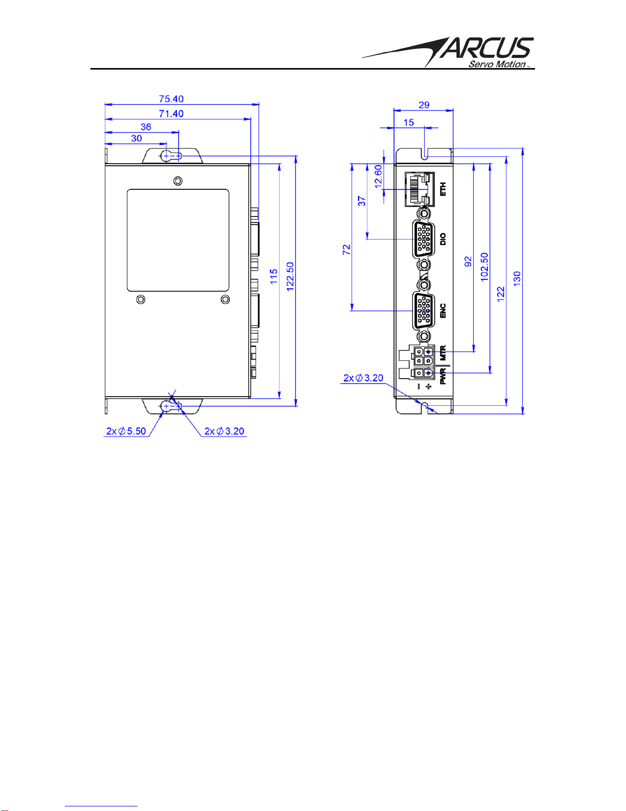
3. DIMENSIONS ............................................................................................................................................. 7
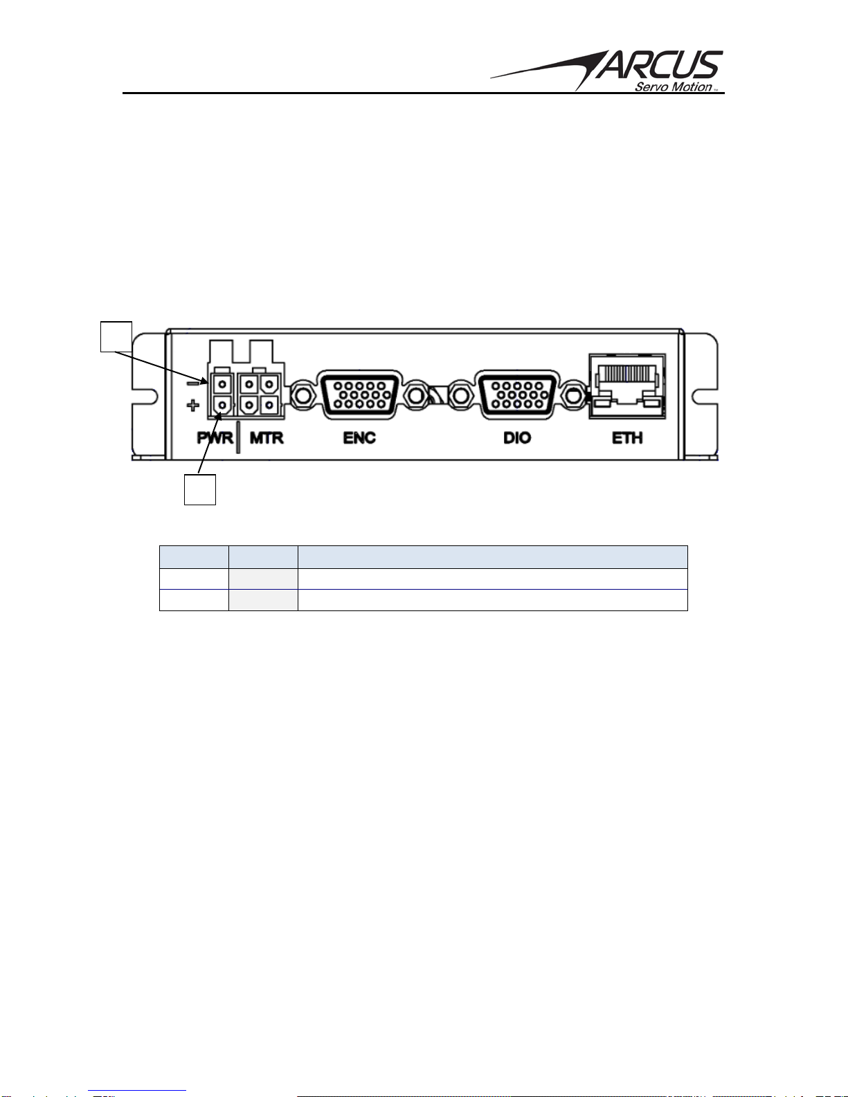
4. CONNECTIVITY ......................................................................................................................................... 8
4.1. 2-PIN POWER CONNECTOR............................................................................................................................8
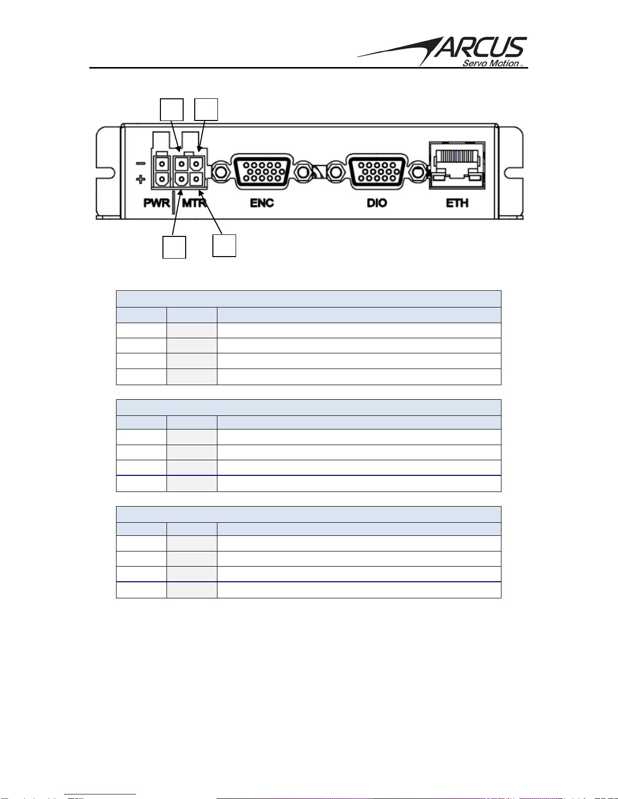
4.2. 4-PIN MOTOR CONNECTOR ...........................................................................................................................9
4.3. MALE DSUB15 (HD) ENCODER/HALL SENSOR CONNECTOR ............................................................11
4.3.1. Encoder Input Circuit.............................................................................................................................12
4.4. MALE DSUB15 (HD) MOTION I/O CONNECTOR .................................................................................. 13
4.4.1. Pulse / Direction (CW/CCW) Inputs................................................................................................14
4.4.2. Digital Outputs ..........................................................................................................................................15
4.5. 3-PIN COMMUNICATION CONNECTION .....................................................................................................16
4.6 USB COMMUNICATION CONNECTION.........................................................................................................16
5. COMMUNICATION....................................................................................................................................17
5.1 ETHERNET COMMUNICATION ......................................................................................................................17
5.1.1. Ethernet Settings......................................................................................................................................17
5.2. SERIAL COMMUNICATION............................................................................................................................ 17
5.2.1. Communication Port Settings ............................................................................................................17
5.2.2. Communicating from PC.......................................................................................................................17
5.2.3. RS-485 Communication Issues...........................................................................................................17
5.3. USB COMMUNICATION ................................................................................................................................ 18
5.3.1. Virtual Communication Settings.......................................................................................................18
5.4. WINDOWS GUI.............................................................................................................................................. 18

TITAN-SVX-ETH Hardware Manual page 4 Rev 4.03
1. Introduction
The TITAN-SVX-ETH is an advanced universal single-axis closed loop servo driver-
controller that supports various types of motors that are commonly used in the
automation industry:
- 2 Phase Stepper Motor
- 3 Phase Brushless Rotary Servo Motor
- 3 Phase Brushless Linear Servo Motor
- DC Voice Coil Motor
In addition to the advanced servo motion control technology, the TITAN-SVX-ETH also
has a number of advanced control technologies including force control, joystick control,
dynamic gains, standalone programming, and many more. Additionally, TITAN-SVX-
ETH enabled with various Servo 5.0 monitoring and analytics algorithm technology for
the Industry 4.0 Smart Factory initiative and the Industrial Internet of Things.

TITAN-SVX-ETH Hardware Manual page 5 Rev 4.03
1.1. Technical Features
- 100 Mbps Ethernet communication (ASCII over TCP/IP)
- USB 2.0 communication (Virtual Com Port)
- RS-485 communication using multi-drop network:
•115200 bps, 8N1
- Communication Protocol supported:
•TITAN-ASCII
•TITAN-ASCII with CRC
•MODBUS-ASCII
•MODBUS-RTU
- Standalone programmable using Arcus A-SCRIPT language with
support of 3 multi-thread programs
- Closed Loop Driver Specifications:
•24-48 VDC
•8.0 Amp max peak current monitoring
- Multiple types of motor support:
•2 Phase Bipolar Stepper Motors
•3 Phase Brushless Rotary Servo Motors
•3 Phase Brushless Linear Servo Motors
•DC Voice Coil Motors
- Configurable in following modes:
•Pulse Mode - digital pulse control using pulse/dir or CW/CCW
•Control Mode – internal motion profile generation with motion
sequence control from internal standalone programming.
- Opto-isolated Digital IO:
•8 bits of digital inputs
•3 bits of digital outputs
- Analog input for speed and joystick control
•0-5V range 12 bit resolution
- A/B/Z differential encoder inputs with A/B/Z single ended encoder
signal outputs
- UVW Hall sensor digital inputs
- Control Mode Features:
•Homing routines using combination of Home/Limit/Z Index
•Soft and Hard Limit Protection.
•Over-current/Over-voltage/ Under voltage/Temperature/Position
Error fault detection

TITAN-SVX-ETH Hardware Manual page 6 Rev 4.03
2. Electrical and Thermal Specifications
Parameter
Min
Max
Units
Main Power Input
1
+24
+48
V
-
8
A
Digital Input Forward Diode Current
-
25
mA
Digital Output Collector Voltage
-
+24
V
Digital Output Sink Current
-
45
mA
Operating Temperature2
-20
+80
°C
Storage Temperature2
-55
+150
°C
Table 2.0
1The supply current should match the driver current setting.
2 Based on component ratings.

TITAN-SVX-ETH Hardware Manual page 7 Rev 4.03
3. Dimensions
Figure 3.0

TITAN-SVX-ETH Hardware Manual page 8 Rev 4.03
4. Connectivity
4.1. 2-Pin Power Connector
In order for the TITAN-SVX-ETH to operate, it must be supplied with +24VDC to
+48VDC power supply. For typical operation, +24VDC power supply is
recommended. For high speed applications, especially with the stepper motors,
48VDC power supply is recommended.
Power pins and communication port pin outs are shown below.
Figure 4.0
Pin #
Name
Description
1
V+
Power Input +24 to +48 VDC
2
G
Power Supply Ground
Table 4.0
Mating Connector Description: 2 pin Mini Fit Jr connector
Mating Connector Manufacturer: Molex
Mating Connector Manufacturer Part: †39-01-2025
† Other compatible connectors can be used.
1
2

TITAN-SVX-ETH Hardware Manual page 9 Rev 4.03
4.2. 4-Pin Motor Connector
Figure 4.1
Depending on the type of motor, follow the motor connection as shown below.
3 Phase BLDC/PMSM Motor (Rotary and Linear)
Pin #
Name
Description
1
V
Motor V
2
U
Motor U
3
W
Motor W
4
NC
No Connection
Voice Coil
Pin #
Name
Description
1
+
Motor +
2
-
Motor -
3
NC
No Connection
4
NC
No Connection
2 Phase Bi-Polar Stepper Motor
Pin #
Name
Description
1
A
Motor A
2
B
Motor B
3
/A
Motor /A
4
/B
Motor /B
Table 4.1
Mating Connector Description: 4 pin Mini Fit Jr connector
Mating Connector Manufacturer: Molex
Mating Connector Manufacturer Part: †39-01-2045
1
2
3
4

TITAN-SVX-ETH Hardware Manual page 10 Rev 4.03
Important Note
Do NOT disconnect the motor wires or motor connector
while the motor is enabled or when motor is moving.
Make sure to turn off the power to the controller or make
sure that the motor is disabled when disconnecting the motor
from the driver.
Plugging or unplugging the motor while the motor is enabled
may damage the motor and/or the electronics.

TITAN-SVX-ETH Hardware Manual page 11 Rev 4.03
28
4.3. Male DSUB15 (HD) Encoder/Hall Sensor Connector
Figure 4.2
Pin #
In/Out
Name
Description
1
I
EA+
Differential Encoder A+ Signal Input
2
I
EA-
Differential Encoder A- Signal Input
3
I
EB+
Differential Encoder B+ Signal Input
4
I
EB-
Differential Encoder B- Signal Input
5
I
EZ+
Differential Encoder Z+ Signal Input
6
I
EZ-
Differential Encoder Z- Signal Input
7
O
+5V
+5V for Encoder and Hall Power
8
O
GND
GND for Encoder and Hall Power
9
O
A
Single Ended Encoder A Output
10
O
B
Single Ended Encoder B Output
11
O
Z
Single Ended Encoder Z Output
12
I
HU
Hall Sensor U Input
13
I
HV
Hall Sensor V Input
14
I
HW
Hall Sensor W Input
15
I
AI1
Analog Input 1
Table 4.2
Mating Connector Description: HD DSUB 15 Male Connector
1
15

TITAN-SVX-ETH Hardware Manual page 12 Rev 4.03
4.3.1. Encoder Input Circuit
Both single ended and differential quadrature incremental encoder inputs are
accepted.
The maximum encoder input frequency is 3MHz
See figure 4.3 for a circuit diagram of the encoder inputs.
Figure 4.3
Notes:
•When using single-ended encoders, use the A-, B-, and Z- inputs.
•EA_OUT/EB_OUT/EZ_OUT signals are encoder output signals that are
available for reading by external controller.

TITAN-SVX-ETH Hardware Manual page 13 Rev 4.03
4.4. Male DSUB15 (HD) Motion I/O Connector
TITAN-SVX-ETH has 8 opto-isolated digital inputs and 3 opto-isolated digital
outputs. Depending on the configuration as Pulse Mode or Control Mode, these
digital signals have different functions.
Figure 4.4
Pin #
In/Out
Pulse
Mode
Control
Mode
Description
1
I
PUL+
DI1+
Pulse Input+ / Digital Input 1+
2
I
PUL-
DI1-
Pulse Input- / Digital Input 1-
3
I
DIR+
DI2+
Dir Input+ / Digital Input 2+
4
I
DIR-
DI2-
Dir Input- / Digital Input 2-
5
I
ENA
DI3
Enable Input / Digital Input 3
6
I
CLR
DI4
Clear Fault Input / Digital Input 4
7
I
RST
DI5
Reset Position Input / Digital Input 5
8
I
DI6
+LIM
Digital Input 6 / + Limit Input
9
I
DI7
HOME
Digital Input 7 / Home Input
10
I
DI8
-LIM
Digital Input 8 / - Limit Input
11
I
DI_COM
DI_COM
Opto-isolated Digital Input Common
12
O
ALM
DO1
Alarm Output / Digital Output 1
13
O
DO2
DO2
Digital Output 2/ Digital Output 2
14
O
INPOS
DO3
In Position Output / Digital Output 3
15
O
DO_COM
DO_COM
Opto-isolated Digital Output Common
Table 4.3
Mating Connector Description: HD DSUB 15 Male Connector
1
15

TITAN-SVX-ETH Hardware Manual page 14 Rev 4.03
4.4.1. Pulse / Direction (CW/CCW) Inputs
In Pulse Mode, TITAN-SVX-ETH supports both one-clock (Pulse/Dir) or two-
clock (CW/CCW) inputs for target position input.
In Controller Mode operation, the corresponding Pulse/Dir inputs can be used as
general purpose input. In Control Mode, the Pulse/CW input is referenced as DI1
and the Dir/CCW input referenced as DI2.
One-clock uses Pulse signal as the amount of movement and Dir signal as the
direction of the movement.
Figure 4.5
Two-clock uses CW as clockwise movement and CCW as counter clockwise
movement.
Figure 4.6
Depending on the direction polarity setting, actual direction of the stepper motor
rotation can be configured for the application. Maximum pulse rate support is 1M
pulses/second.
Pulse/Dir (CW/CCW) inputs are opto-isolated differential inputs with 270Ω
resistor as shown in figure 4.7. Maximum source current for the diode is 25mA.
Important Note: If voltage across is greater than 5V, make sure to add current
limiting resistor to limit the current to 50mA across the diode. Figure 4.7 shows
the detailed schematic of the opto-isolated pulse and direction inputs.
Figure 4.7

TITAN-SVX-ETH Hardware Manual page 15 Rev 4.03
4.4.2. Digital Outputs
In Pulse Mode, three digital outputs are designated as INPOS, ALARM outputs.
Third digital output is general purpose output.
In Control Mode, three digital outputs are available for general purpose use.
Figure 4.8 shows an example circuit of the digital outputs for TITAN-SVX-ETH
Figure 4.8
The DO_COM must be connected in order for the digital outputs to operate.
4.4.3 Digital Inputs
In Pulse Mode, the following digital inputs are available: Enable, Reset, and Clear.
Three other digital inputs are general purpose inputs.
In Control Mode, the following digital inputs are available: +Limit, Home, and -Limit.
Remaining 3 digital inputs are available for general purpose use. Note that in
Control Mode, limit inputs can be disabled and these limit inputs can be used as
general purpose inputs.
Figure 4.9 shows the detailed schematic of the opto-isolated digital inputs available
on the TITAN-SVX-ETH.
Figure 4.9
The DI_COM must be connected in order for the digital inputs to operate

TITAN-SVX-ETH Hardware Manual page 16 Rev 4.03
4.5. 3-Pin Communication Connection
TITAN-SVX-ETH supports serial RS-485 communication.
Figure 4.10
Pin #
Name
Description
1
485+
Positive RS485 Signal
2
485-
Negative RS485 Signal
3
GND
Ground
Table 4.4
4.6 USB Communication Connection
TITAN-SVX-ETH supports USB 2.0 communication.
Mini-B connector USB communication cable is used to communicate with a
master such as PC.
Figure 4.11
3
1
Mini-B USB

TITAN-SVX-ETH Hardware Manual page 17 Rev 4.03
5. Communication
5.1 Ethernet Communication
TITAN-SVX-ETH uses 100Mbps Ethernet ASCII communication over TCP/IP
5.1.1. Ethernet Settings
The default IP address/socket settings can be found below
IP: 192.168.1.100
Port: 5000
To begin communication with a factory default device, configure the PC control
panel with the following settings:
IP = 192.168.1.nnn
Subnet Mask = 255.255.255.0
Note that the host IP address of the PC should differ from the IP address of the
TITAN-SVX-ETH.
5.2. Serial Communication
The TITAN-SVX-ETH communicates over an RS-485 interface.
5.2.1. Communication Port Settings
The TITAN-SVX-ETH has communication port settings as shown in Table 5.0.
Parameter
Setting
Baud Rate
115,200
Byte Size
8 bits
Parity
None
Flow Control
None
Stop Bit
1
Table 5.0
5.2.2. Communicating from PC
Use the TITAN-SVX-ETH Windows User Interface available for download from
the Arcus TITAN website.
.
USB to RS-485 converter will be required to communicate from PC to the TITAN-
SVX-ETH.
5.2.3. RS-485 Communication Issues
RS-485 communication issues can arise due to noise on the RS-485 bus. The
following techniques can be used to help reduce noise issues:

TITAN-SVX-ETH Hardware Manual page 18 Rev 4.03
Daisy Chaining
For a multi-drop RS-485 network, be sure that the network uses daisy-
chain wiring.
Number of Nodes
The maximum number of nodes recommended is 32. Increasing beyond
this number will require special attention
Twisted Pair Wiring
To reduce noise, it is recommended to use twisted pair wiring for the 485+
and 485- lines. This technique will help cancel out electromagnetic
interference.
Termination
For an RS-485 network, it may be required that a 120 Ohm resistor is
placed in between the 485+ and 485- signals, at the beginning and end of
the bus. A terminal resistor will help eliminate electrical reflections on the
RS-485 network.
Note that on short communication buses, or buses with a small number of nodes,
termination resistors may not be needed. Inclusion of terminal resistors when
they are not needed may mask the main signal entirely.
5.3. USB Communication
The TITAN-SVX-ETH uses USB 2.0 Virtual Communication.
5.3.1. Virtual Communication Settings
The TITAN-SVX-ETH uses same communication port settings as the serial
communication setting as shown in Table 5.0.
Parameter
Setting
Baud Rate
115,200
Byte Size
8 bits
Parity
None
Flow Control
None
Stop Bit
1
Table 5.1
5.4. Windows GUI
The TITAN-SVX-ETH comes with a Windows GUI program to setup, configure,
test, program, compile, download, and debug the controller. The Windows GUI
will perform all communication via RS-485. See TITAN-SVX-ETH Software
Users Manual for more details.

TITAN-SVX-ETH Hardware Manual page 19 Rev 4.03
Contact Information
Arcus Servo Motion, Inc.
3159 Independence Drive
Livermore, CA 94551
925-373-8800
www.arcusservo.com
The information in this document is believed to be accurate at the time of publication but is
subject to change without notice.
Table of contents
Other Arcus Controllers manuals
Popular Controllers manuals by other brands

CBS
CBS ArcSafe RSA-161A Installation and operation

NEC
NEC N8103-199 SAS user guide

Thomson Power Systems
Thomson Power Systems Marathon MEC 20 Installation, operating & service manual

Precision Digital Corporation
Precision Digital Corporation ConsoliDator Plus PD9000 instruction manual

Toshiba
Toshiba TC78B002FNG manual

Shimaden
Shimaden FP23 Series instruction manual