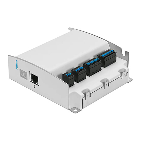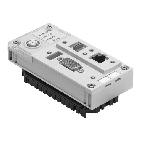
Axis controller CPX-CMAX
4 Festo – P.BE-CPX-CMAX-SYS-EN – en 2017-09b – English
3.4.1 Approved drive/valve combinations 28..................................
3.4.2 Mounting the VPWP proportional directional control valve 30.................
3.5 Mounting the CASM sensor interface 32..........................................
3.6 Pneumatic installation 33.....................................................
3.6.1 Compressed air supply 33.............................................
3.6.2 Filter regulator 34...................................................
3.6.3 Air pressure reservoir (optional) 34.....................................
3.6.4 Proportional directional control valve VPWP and drive 34....................
3.6.5 Compressed air tubing and fittings 38...................................
4 Electrical installation 39......................................................
4.1 Safety instructions 39........................................................
4.2 Earthing 40.................................................................
4.3 Axis connection 41...........................................................
4.3.1 Proportional directional control valve VPWP 42............................
4.3.2 Sensor interface CASM 43............................................
4.4 Power supply 44.............................................................
4.4.1 Determining the current consumption 44.................................
4.4.2 Power supply concept, formation of power zones 45........................
5 Commissioning 48...........................................................
5.1 Important notes on commissioning 48...........................................
5.2 Parameterisation and commissioning options 49...................................
5.2.1 Communication profile FHPP 49........................................
5.2.2 Festo Configuration Tool (FCT) 49.......................................
5.3 Preparations for commissioning 52..............................................
5.3.1 Checking the axis string 52............................................
5.3.2 Switching on the supply voltage, switch-on behaviour 52....................
5.3.3 Make connection to the PC 54..........................................
5.4 Commissioning with the FCT (overview) 55........................................
5.4.1 Overview of commissioning steps 55....................................
5.5 Notes on operation 56........................................................
5.5.1 Control of the CMAX 56...............................................
5.5.2 General instructions on operation 56....................................
6 Diagnostics and error handling 57..............................................
6.1 Summary of diagnostics options 57.............................................
6.2 Diagnostics via LEDs 58.......................................................
6.2.1 CMAX-specific LEDs 59...............................................
6.2.2 Axis-specific LEDs 59.................................................
6.2.3 LEDs at the proportional directional control valve VPWP 60..................
6.2.4 LEDs at the sensor interface CASM 61...................................
