Device allocation and power-down retention instructions
X00-X13 12 points
X00-X27 24 points
Y00-Y13 12 points
Y00-Y23 20pints
Auxiliary relay M
Status S
[S0-S9] 10 points original state/ [S10-S999] 990 points, maintain/ [S1000-S4095] 3096 points, general
Timer T
[T0-T199] 200 points, 100ms, general / [ T250-T255] 6 points, 100ms, maintain/
[T246-T249] 4 points, 1ms accumulation, maintain / [T256-T319] 64 points, 1ms, general use/
[T200-T245] 46 points, 10ms, general use/
* 10ms timer is affected by scan cycle. If scan cycle is 12ms, the timer will work every 12ms.
EX3G-43HB 43H/43(50)KH-24M/
Programming reference
DI X
DO Y
[M0-M383] 384 points, general / [M384-M1535] 1152 points, maintain/ [M1536-M7679] 6144 points, general/
[M8000-M8511] 512 points, special
EX3G-70H-44M
EX3G-70KH/100HA-60M
◆
Counter C
[C0-C15] 16 points, genera / /
[C200-C219] 20 points, general use/[C220-C234] 15 points, maintain use/
[C235-C245 single phase single count], [C246-C250 single phase double count] ,[C251-C255 double phase double count]
use [C16-C199] 184 points, maintain use
Data register V,Z
[V0-V7] [Z0-Z7] 16 points, used while modifying address
[D0-D127] 128 points, general / [D128-D7999] 7872 points, maintain /
[D8000-D8511] 512 points, special use
Nested pointer
[N0-N7] 8 points, master use
Constant
K
H
16 bits -32,768-32,767/32 bits -2,147,483,648-2,147,483,647
16 bits 0-FFFFH/32 bits 0-FFFFFFFFH
Tips……………………….........………………………...............……01
Product Features…………………………………………...………02
Product Information……………………………………..…………03
Electric Parameter………………………………………….………04
Mechanical Design…………………………………………......….05
Electric Design……………………………………….............…….06
Equivalent circuit……………………………………………………07
Analog Wiring…………………………………………...........……..08
Anti-interference Processing…………………….……………..09
Programming Reference…………………………………………10
Data Reference………………………………………………...……11
Shenzhen Coolmay Technology Co., Ltd
Tel.: 0755-86950416
86960332
26051858
26400661
Fax: 0755-26400661-808
QQ: 800053919
Website: https://en.coolmay.com/
Version: 2020/6
Catalog
X00-X35 30 points
Y00-Y35 30 points
[I0□□~I5□□] 6 points, input interruption use/ [I6□□~I8□□] 3 points, timer interruption use/
——
EX3G HMI PLC All-in-One User Manual
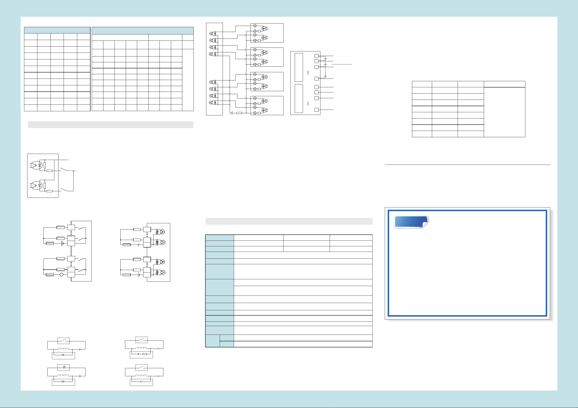
Figure 6 Input wiring
Figure 7 Equivalent circuit of relay output Figure 8 Equivalent circuit of transistor output
Figure 9 Inductive load absorption circuit
Figure 10 Pulse output wiring
Note: All internal circuit in the figure are taken as reference.
※
Equivalent Circuit
The PLC input (X) is an externally powered DC24V sinker (passive NPN) and the input signal is isolated
from the power supply. Connect COM to positive 24V of external power supply while using.
Figure 7 shows the equivalent circuit diagram of the relay output module. The output terminals are several
groups and each group is electrically isolated. Different groups of output contacts are connected to different
power circuits.
COM0
Y003
Y000
COM1
Y007
Y004
DC24V
Fuse
Load
AC0~220V
~
sinker output
DC24V
DC24V
COM0
Y003
Y000
COM1
Y007
Y004
COM0
Y1
COM2
Y10
COM1
Y4
R=200Ω C=0.22uF,250VAC
RC
~
COM1
Y5
~
FWD 1N404
FWD 1N404
PLC relay output
inductive load
AC220V power supply
AC220V power supply
varistor 10D471k (undercurrents)
+
-
+
-
+
-
+
-
+
-
+
-
+
-
+
-
R
COM1
Y4
Y5
Y6
Y7 Direction
Pulse
COM0
Y0
Y1
Y2
Y3
PLC internal
equivalent
circuit
DC24V(5V drive must string 2kΩ resistor)
GND
AD0
AD1
AD15
+
104p
GND
DA0
DA1
DA7
AD
AD COM terminal
( )AD 1
104p +( )AD 2
* Please consider adding 104p ceramic capacitor or external
magnetic ring filter to increase anti-interference ability if analog
inputs are unstable.
104p
+( )AD 16
-
DA COM terminal
+( 8)DA
+( 2)DA
+( 1)DA
* Analog input is AD0-AD15 and output is DA0-DA7. Negative
terminals are connected to GND of input and output respectively.
One negative voltage output will occupy 2 DA and max 4 negative
voltage outputs can be optional. (Only connect DAx and GND.
Please be subject to the test report in your package. )
The equivalent circuit of the transistor PLC output is shown in Figure 8. Seen from the figure, the output
terminals are several groups, and each group is electrically isolated, and different groups of output contacts can
be connected to different power circuits. The transistor output can only be used for DC 24V load circuits. Output
wiring is NPN, COM cathode.
For the inductive load connected to the AC circuit, the RC transient voltage absorption circuit should be
considered on the external circuit. For the inductive load of the DC loop, adding a freewheeling diode should be
considered, as shown in Figure 9.
Stepping or servo motor wiring is shown in Figure 10. 5V drive must connect a 2KΩ resistor on DC24V.
4-channel pulse are Y0, Y1, Y6, Y7, and customized 5-channel are Y0, Y1, Y6, Y7 and Y10.
PLC anti-jamming processing
1. Strong electricity and weak electricity should be separated wiring and not common ground. When there is
strong electric interference, add magnetic ring on the power supply. And do correct and effective grounding
according to the type of the chassis.
2. When the analog is disturbed, 104 ceramic capacitors can be added for filtering, and a correct and effective
grounding can be performed.
More details please refer to Methods of Coolmay PLC anti jamming processing
* , " - "
PLC analog wiring
Two-wire system: The positive pole of the power supply is connected to that of the transmitter, and the negative
pole of the transmitter is connected to the AD side, and the negative pole of the power supply
is connected to the GND. Generally it is the wiring method of the 4-20MA/0-20MA transmitter.
Three-wire system: The positive pole of the power supply is connected to that of the transmitter. The negative of
the power supply and that of the signal output are the same terminal. The transmitter signal
output is connected to the AD terminal.
Four-wire system: The positive and negative terminals of the power supply are connected to those of the
transmitter respectively, and the positive and negative of the transmitter signal outputs are
connected to the AD and the GND terminal respectively.
The two wires of the temperature analog are connected to the AD and the GND terminal respectively. If it is a
three-wire PT100, it needs to be connected in two lines. The GND common terminal of the analog input and
output can be shared.
Load
Load
Load
Load
Load
Load
Load
Fuse
Fuse
Fuse
PLC relay output
inductive load
PLC relay output
inductive load
DC24V power supply
PLC transistor output
inductive load
DC24V power supply
Figure 11 PLC analog wiring
Direction
Pulse
Direction
Pulse
Direction
Pulse
DA
TIPS Please read carefully the related manuals before using our
products, and use this product under the environmental
conditions specified in this manual.
1. Power on after confirmed the voltage (24VDC, >18W) and right wiring to avoid damage.
2. Tighten the screws or the rail while mounting the product to avoid falling off.
3. Avoid wiring or plug the cable with electricity, or it is easy to cause electric shock or circuit
damage. When the product emits odor or abnormal sound, please immediately switch off the
power. While processing screw holes or wiring, do not drop the metal chips and wire head into
the ventilation hole of the controller, which may cause product failure and disoperation.
4. Do not tie power cables and communication cables together or close and keep them at a
distance of 10cm or more. Strong and weak currents need to be separated and correctly
grounded. In severe interference situations, input and output cables of the communication and
high-frequency signals should use shielded cables to improve anti-jamming performance. The
grounding terminal FG on this unit must be properly grounded to improve the anti-interference
ability.
5. DI is an externally powered DC24V sinker (passive NPN), and the input signal is isolated from
the power supply. Connect S/S to 24V of external power supply while using.
6. DO (transistor) COM is common cathode.
7. Please do not disassemble the product or change the wiring. Or it will possible to cause
breakdown, malfunction, loss, or fire.
8. While installing or disassembling the product, ensure to turn off all power. Or it may cause
malfunction and breakdown.
* Programming software
PLC: compatible with Mitsubishi PLC programming software GX WORKS 2.
HMI: Coolmay HMI programming software
* Detailed information, please refer to
“Coolmay EX3G HMI PLC All-in-One Programming Manual”,
“EX3G HMI PLC All-in-One User Manual”,
“Coolmay HMI User Manual”,
“Mitsubishi FX3G Programming Manual”
The soft elements power retentive of HMI PLC all-in-one is permanently retentive, i.e., all the soft
elements in the holding area are not lost if the module is powered off. The real-time clock uses a
rechargeable battery to ensure that the clock is the current time. All power retentive functions must ensure
that the voltage is 23V or higher when DC24V power supply with loads, and the PLC power-on time is
longer than 2 minutes. Otherwise, the power retentive functions will be abnormal.
◆
No Register
address
D8050
D8051
D8052
D8053
D8054
D8055
D8056
D8057
Range of set
value
0-4000
0-4000
0-4000
0-4000
0-4000
0-4000
0-4000
0-4000
Output type
※
◆
※
Registers read directly: D[8030]-D[8045] are the input values of [AD0~AD15].The constant scan-time will change to D8059
and started by M8039 (version 26232 and higher). It supports max 15 analog inputs when there exist thermocouple type, and
AD4[D8034] is the ambient temperature of thermocouples. It supports max 16 analog inputs without thermocouples.
Analog input register (AD,accuracy 12 bits). Support FROM demand or register read directly.
The temperature type is one digit after the decimal point, i.e. 182 = 18.2 degrees.
AD sampling
Filter cycles = (R23600~R23615)* scan time of the PLC. The default value is 100 and the data cannot be
less than or equal to zero. If R23600=1, one PLC scan cycle samples once, and the value in the first analog
input is changed once. The larger the value of R23600~R23615 is set, the more stable the result is.
D8073 is the smoothing filter coefficient of all analog inputs. The setting range is 0~999.
Analog output register (DA,accuracy 12 bits). Support TO demand or direct register assignment.
TO demand direct outputs: TO K0 K0 D500 K8 , 8 analog outputs
DA0
DA1
DA2
DA3
DA4
DA5
DA6
DA7
If D8058.0~D8058.7=0,
output type is 0-20mA.
If D8058.0~D8058.7=1,
the type is 4-20mA.
16 bits (CTU)/ / increase counter 32 bits increase and decrease counter (CTUD) High speed counter
1K
3.9K
COM
X0 0V
X1
1K
3.9K
24V
EX3G-43HB/43H/43(50)KH all-in-one COM
PIN#PLC-485-2
serial port 3PLC-485-1
serial port 2
PLC-232
serial port 3HMI-232
Optional Default Optional
8
9
Terminal 485
√(485+)
√(485-)
√
√(RXD)
√(TXD)
√(GND)
√(GND)
√(TXD)
√(RXD)
EX3G-70H/70KH/100HA all-in-one COM(EX3G-70H can't support WIFI)
PIN#
PLC-485-1
serial port 2
D 9 portb Default Optional
8
9
√(485+)
Optional and
default 232
cannot coexist
PLC-485-2
serial port 3
PLC-232
serial port 3
Optional and
default 232、
Optional WIFI
cannot coexist
Optional and
default 232、
Optional 485
cannot exist
WIFI
Optional
PLC-CAN
Optional
COM2(DB9 port near power supply)
HMI-485
HMI-232
Optional
√(485+)
√(485-)
√(485-)
√(RXD)
√(TXD)
√(GND)
√(H)
√(L)
Optional
√(RXD)
√(TXD)
√(GND)
√
√
√
√
√
√(485+)
√(485-)
1
6
2
3
5
4
7
1
6
2
3
5
4
7
COM1
DB9 port
COM1(DB9 port away from power supply)
Network
port
Network
port of
HMI and
PLC do not
occupy
serial port
signal,
and can
not coexist.
Chart 4: Pin definition
* Note: Detailed settings, please refer to "Coolmay EX3G Programming Manual".
Figure 7 shows the equivalent circuit diagram of the relay output module. The output terminals are several
groups and each group is electrically isolated. Different groups of output contacts are connected to different
power circuits.
PLC digital inputs wiring:
Ports short circuit: S/S of PLC input terminal is connected to 24V, X terminal is connected to
power supply 0V, i.e., input signal.
Two-wire system (magnetic control switch): The positive pole of the magnetic switch is
connected to PLC X terminal, and the negative pole is connected to 0V.
Three-wire system (photoelectric sensor or encoder): Sensor or encoder power supply is
connected to power supply positive, signal line is connected to X terminal. Encoder
and photoelectric sensor are NPN type (PNP is customized).
PLC digital outputs wiring:
Transistor: Output is NPN, COM is connected to the negative pole, and Y is connected to
the positive pole of the power supply with a load.
Relay: Dry contact output, COM can be connected to the positive or negative.
Data register D
[R0-R22999] 23000 points, support power retentive/ [R23000~R23999] 1000 points, system internal use
Extended file register R
Pointer JUMP,CALL branch use
[P0-P255] 256 points/ [ - ] points and higher versionP0 P1280 1281 (26232 )
Interruption
[I10□□~I60□□] 6 points, timer interruption use
FROM demand read: FROM K0 K0 D400 K16 can be read as 16-channel analog inputs.
Note Analog input range and register values please refer to Coolmay EX3G HMI PLC All in One Programming Manual: , " - - ".
※
※
TO demand direct outputs: D[8050]~D[8057] correspond to the values of [DA0~DA7].
When select negative outputs, 2 analog outputs will be covered. The configuration is as the
chart below.
(*1)
Max digital points


