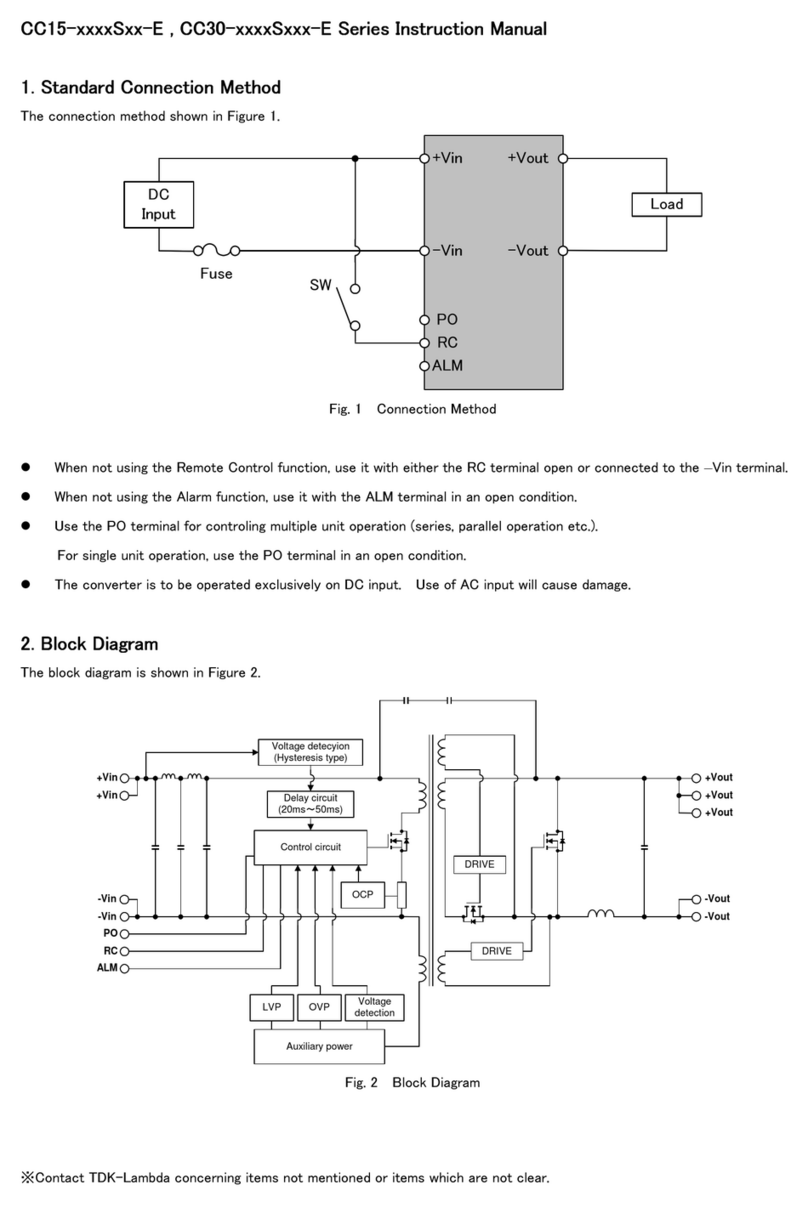
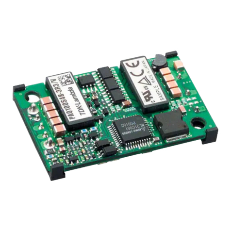
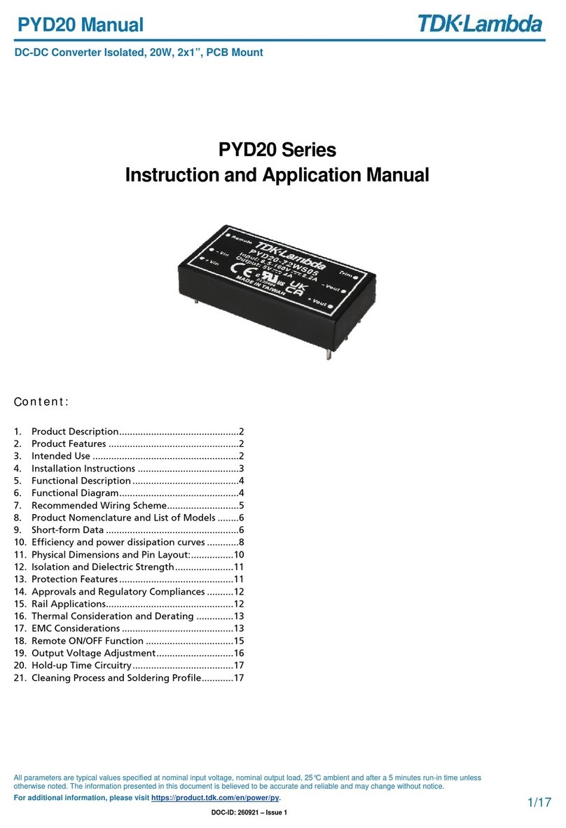
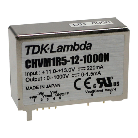
TDK-Lambda CHVM1R5 Series User manual

INSTRUCTION MANUAL
CHVM1R5 Series
TDKLambda
<Page>
BEFORE USING THE POWER SUPPLY UNIT
Be sure to read this instruction manual thoroughly before using this product. Pay attention to all cautions and warnings before
using this product. Incorrect usage could lead to an electrical shock, damage to the unit or a fire hazard.
DANGER
Never use this product in locations where flammable gas or ignitable substances are present.
INSTALLATION WARNING
・When installing, ensure that work is done in accordance with the instruction manual. When installation is improper,
there is risk of electric shock and fire.
・Installation shall be done by Service personnel with necessary and appropriate technical training and experience.
There is a risk of electric shock and fire.
・Do not cover the product with cloth or paper etc. Do not place anything flammable around. This might cause damage,
electric shock or fire.
WARNING ON USE
・Do not touch this product or its internal components while circuit in operation, or shortly after shutdown. You may
receive a burn.
・While this product is operating, keep your hands and face away from it as you may be injured by an unexpected situation.
・There are cases where high voltage charge remains inside the product. Therefore, do not touch even if they are not in
operation as you might get injured due to high voltage and high temperature. You might also get electric shock or burn.
・Do not make unauthorized changes to this product nor remove the cover as you might get an electric shock or might
damage the product. We will not be held responsible after the product has been modified, changed or disassembled.
・Do not use this product under unusual condition such as emission of smoke or abnormal smell and sound etc. Please stop
using it immediately and shut off the product.
It might lead to fire and electric shock. In such cases, please contact us. Do not attempt repair by yourself, as it is
dangerous for the user.
・Do not operate and store these products in environments where condensation occurs due to moisture and humidity.
It might lead fire and electric shock.
・Do not drop or apply shock to this product. It might cause failure. Do not operate these products mechanical stress is
applied.
CAUTION ON MOUNTING
・Confirm connections to input/output terminals are correct as indicated in the instruction manual before switching on.
・Input voltage, Output current, Output power, ambient temperature and ambient humidity should be kept within
specifications, otherwise the product will be damaged.
・Input line, please use the wires as short and thick as possible.
・Do not use this product in special environment with strong electromagnetic field, corrosive gas or conductive substances
and direct sunlight, or places where product is exposed to water or rain.
・Please shut down the input when connecting input and output of the product.
・When installing in environment where conductive foreign, dust and liquid may be present,
please consider penetration of above foreign material in the power supply by installing filter, to prevent trouble or
malfunction.
1/11 QC0010401
CHVM1R5 Series
Instruction Manual
INSTRUCTION MANUAL
CHVM1R5 Series
TDKLambda
<Page>
CAUTION ON USE
• Product individual notes are shown in the instruction manual. If there is any difference with common notes individual
notes shall have priority.
• Before using this product, be sure to read the catalog and instruction manual. There is risk of electric shock or damage
to the product or fire due to improper use.
• Input voltage, Output current, Output power, ambient temperature and ambient humidity should be kept within
specifications, otherwise the product will be damaged, or cause electric shock or fire.
• Insert fuse at the input to prevent smoke, fire during abnormal operation.
• For externally mounted fuse do not use other fuses aside from our specified and recommended fuse.
• This product was made for general purpose electronic equipment use and is not designed for applications requiring
high safety (such as extremely high reliability and safety requirements. Even though high reliability and safety are not
required, this product should not be used directly for applications that have serious risk for life and physical safety.
Take sufficient consideration in failsafe design (such as providing protective circuit or protective device inside the
system, providing redundant circuit to ensure no instability when single device failure occurs).
• When used in environments with strong electromagnetic field, there is possibility of product damage due to malfunction.
• When used in environment with corrosive gas (hydrogen sulfide, sulfur dioxide, etc.) , there is possibility that they might
penetrate the product and lead to failure.
• When used in environments where there is conductive foreign matter or dust, there is possibility of product failure or
malfunction.
• Provide countermeasure for prevention of lightning surge voltage as there is risk of damage due to abnormal voltage.
• Take care not to apply external abnormal voltage to the output. Especially, applying reverse voltage or overvoltage more
than the rated voltage to the output might cause failure, electric shock or fire.
NOTE
• Take note that traces of sheet metal processing be left in our power supplies.
• When disposing product, follow disposal laws of each municipality.
• When exporting our products, apply for necessary permissions as required by rules and regulations of Foreign Exchange
and Foreign Trade Control Act.
• Catalogue, contents of the instruction manual may be changed without a prior notice. Refer to latest catalogue or
instruction manual.
• Reproduction or reprinting the instruction manual or its portion is forbidden without our permission.
2/11

INSTRUCTION MANUAL
CHVM1R5 Series
TDKLambda
<Page>
LONGTERM STORAGE METHOD AND LONGTERM STORAGE PERIOD
• Please keep the product in carton box.
• Please do not apply excessive vibration, shock or mechanical stress applied directly to the product.
• Please keep away from direct sunlight.
• For longterm storage temperature and humidity, the following conditions shall be used as a guideline :
Temperature range : 5℃~30℃
Humidity range : 40%~60%RH
Please keep away from the places where temperature and humidity can change drastically.
It can cause condensation on the product or deterioration.
• For longterm storage period, we recommend to use within 1 years after receiving the product.
< Soldering and PCB mounted products : On Board, Power Module and etc >
For products that have been received for more than 1 year, please check lead oxidation and solderability.
3/11

INSTRUCTION MANUAL
CHVM1R5 Series
TDKLambda
<Page>
The CHVM series is mediumhigh voltage DCDC converters featuring an ultracompact size.
With a pentahedron metal shield case, ripple noise has been reduced to as low as 5mVpp. Output voltage can be
adjusted by external voltage or external variable resistor. The builtin short circuit and overcurrent protection
provide high reliability and a long life.
■ Features
•Ultralow ripple noise 5mVpp •Builtin over current protection circuit
•Smallest size •ON/OFF Control
•Adjustable output voltage from 0 to 100% •Adjustable voltage by variable resistor
•Control voltage 0 to +6V or external voltage
•Output capacity 1.5W •Use of pentahedron metal shield case
•UL / cUL 609501 certified product •PCB mount type
•CE marking •High reliability and long life
■ Model name/Rating
■ Specifications
Note 1 : Output voltage is controlled by applying Vcont voltage. Apply voltage to the Vcont terminal by either
variable resistor or external voltage to control output voltage.
When Vcont voltage is zero, output voltage (output residual voltage) will be within 0.5% of maximum
output voltage (input/output rating).
Note 2 : Details are subject to change for improvement, etc., without prior notice.
4/11
Line regulation
Load regulation
Temperature regulation
Over current protection
Output voltage setting accuracy
Operating temp range
Storage temp range
Operating humidity range
Isolation between input and output
0.02% typ. (for a load current regulation of 0 to 100%)
70ppm/°C typ. (for temperature regulation of 10°C to +50°C)
10°C to +50°C (no temperature derating needed)
Nonisolated type (2pin through 6pin are connected inside)
20% to 95% RH (no condensation)
25°C to +85°C
Either with 0V to +6V external voltage or a 5KΩ external variable resistor
±2% or less (when controlling a 6.0V external voltage)
Drooping characteristic, builtin automatic return circuit, activated at 105% or more
0.01% typ. (for a line regulation of 11.0 to 13.0V)
Between 2pin and 5pin, OFF when opened and ON when shortcircuited.
Output voltage control
MTTF expectation 600,000Hours(min)
ON/OFF control
Output Voltage
(Vdc)
Models CHVM series
11.0~13.0 0~+1000 666.7
Output Current
(mA)
Load Resistance
(KΩ) min
Input Current
(A) typ
Ripple Noise
(mVpp) typ
Input Voltage
(Vdc)
0.22 5CHVM1R5121000P
CHVM1R5121000N
CHVM1R5121500P
CHVM1R5121500N
11.0~13.0 0~1000 0.22
0.23
0.25
5
7
7
11.0~13.0
11.0~13.0
0~+1500
0~1500
0 ~ 1.5
0 ~ 1.5
0 ~ 1.0
0 ~ 1.0
666.7
1500
1500
11.0~13.0 0~+2000 2857 0.28 10CHVM1R5122000P
CHVM1R5122000N 11.0~13.0 0~2000 0.28 100 ~ 0.7
0 ~ 0.7
2857

INSTRUCTION MANUAL
CHVM1R5 Series
TDKLambda
<Page>
■ Test circuit
(1) The inputoutput ground lines and the case are connected inside.
(2) Vref is 6V (when external VR is 5KΩ)
(3) ON/OFF can be controlled by a transistor.
■ Block diagram
5/11
12V
SW1
Load
1
2
4
6
3
SW1
Open=OFF
Short=ON
+
C1
5
7
+
Output voltage control
(0V to 6V applied)
C1=47μF
(OPEN)
+Vin
-Vin
Vout (+ or -)
Vout
(Com)
Vref
Vcont
ON/OFF
CASE
F1
12V
+
+
+Vin
-Vin
Vout (+ or -)
Vout(Com)
Vcont
Vref
Load
1
2
7
6
3
4
Control IC
Output voltage control
Over current protection
Reference voltage generator
Voltage detection
Case
External voltage(0~6V)
or
VR (5kΩ)
5
ON/OFF
Open=OFF
Short=ON
ON/OFF
Control
DCAC
converter
Highvoltage
oscillation
transformer
Highvoltage
rectifier

INSTRUCTION MANUAL
CHVM1R5 Series
TDKLambda
<Page>
■ Shape, dimensions and terminal composition
1) Terminal
Material: Phosphor bronze
Treatment: Ni base Au plating
2) Case
Material: Brass
Treatment: Nickel plating
Weight: 50g typ.
Unit: mm
Unspecified dimensional
tolerance ±0.5
( Bottom view )
■ Standard usage instructions
The CHVM series does not basically require additional parts, but add capacitor C1 to the input terminal if input
impedance is high due to a long distance between the power supply and converter, an input line is thin, a filter is
inserted on the input side, etc. When fitting a capacitor, try to add on the converter terminal side so as to reduce
lead inductance.
6/11
PinNo.
1
2
3
4
5
6
Pin name
Vout(Com)
ON/OFF
Vref
Vcont
Vin
+Vin
7 Vout (+ or )
30.0
0.5
2.0
16.044.0±0.5
0.5
4.0
35.5
2×CASE PIN
7.0
7-□0.64
7.62
±0.3
7.62
±0.3
5.08
±0.3
2.54±0.1
2.54×4=10.16
12V
SW1
Load
1
2
4
6
3
SW1
Open=OFF
Short=ON
+
C1
5
7
+
Output voltage control
(0V to 6V applied)
C1=47μF
(OPEN)
+Vin
-Vin
Vout (+ or -)
Vout
(Com)
Vref
Vcont
ON/OFF
CASE
F1
CHVM1R5121000P
Input : +11.0+13.0V
Output : 0+1000V
1 2 3 4 5 6 7
220mA
01.5mA
MADE IN JAPAN
Vin Vref
+Vin Vcont ON/OFF Vout(Com) Vout(+)
4.2min

INSTRUCTION MANUAL
CHVM1R5 Series
TDKLambda
<Page>
■ ON/OFF Control
Output voltage can be turned ON/OFF by closing/opening between the ON/OFF terminal and Vin terminal.
Between ON/OFF terminal (5) and Vin terminal (2)
(1) Output OFF when opened
(2) Output ON when shortcircuited (0 0.4V, 1mA max.)
As the ON/OFF terminal is pulled up to +Vin inside the power supply, pay attention to the voltage of elements
(photocoupler, transistor, etc.) to switch the ON/OFF terminal.
Shortcircuit when ON/OFF is not controlled.
Ensure that there is no chattering to the ON/OFF terminal which affects output voltage. Output residual voltage is
0.5% or less when output is OFF under ON/OFF control (at the rated inputoutput).
■ Over current protection
The CHVM series has a builtin over current protection circuit against overload and load shortcircuit. The circuit
reduces output voltage in case of overload or load shortcircuit and automatically returns the output to normal
when the cause is eliminated.
The overcurrent protection circuit shows a drooping characteristic. Ensure that the load to be used is at least with
the minimum resistance specified for each series.
7/11
Isolated type
-Vin
ON/OFF
(5)
(2)
Nonisolated type
-Vin
ON/OFF
(5)
(2)
100
80
60
40
20
00Output Current (lo) 100%
100% output
50% output
Output voltage setting value (%)
CHVM series
over current protection circuit
characteristic

INSTRUCTION MANUAL
CHVM1R5 Series
TDKLambda
<Page>
■ Recommended pattern
[mm]
(1) The CHVM series uses a metal case. When mounting onto a doublesided board, wiring to this converter
should be on a soldered surface. When wiring, pay enough attention to creepage distance because of the high
voltage of this converter.
(2) When mounting onto a doublesided board, make the round on the parts surface of the high voltage output
terminal as small as possible.
(3) Connect the case of the CHVM series to Vin or Com. Try to reduce impedance to the ground as much as
possible.
8/11
7- Hole dia. : φ1.2 2- Hole dia. : φ2.5
17.75
8.75
7.62
±0.3
7.62
±0.3
5.08
±0.3
2.54±0.1
2.54×4=10.16
6.75
17.75
(Top view)

INSTRUCTION MANUAL
CHVM1R5 Series
TDKLambda
<Page>
■ Setting and adjustment of output voltage
The output voltage of the CHVM series can be set and adjusted by external voltage and external variable resistor.
●In the above characteristic graph (output voltage VR resistance characteristic), the resistance R1 and R2 are for
a guideline. When setting output at a fixed voltage with a fixed resistor, do so after determining R1 and R2 using
a variable resistor.
●Do not apply 6V+3% or more voltage to Vcont.
●Use a variable resistor with a good temperature coefficient.
●It is preset that when the resistance of the variable resistor is 5.0KΩ, 6.0V is applied to the Vcont terminal to
obtain 100% output voltage. Since the tolerance of the resistance value largely affects the maximum output
voltage, set the resistance value at 5.0KΩ±5%.
9/11
100%
80%
60%
40%
20%
0%
Output voltage – VR resistance characteristic
VR resistance
R1 5kΩ
R2 0kΩ
0kΩ
5kΩ
Output voltage (%)
Output voltage – output control voltage characteristic
0V
100%
80%
60%
40%
20%
0%
6V
4.5V
3V1.5V
Output control voltage
Output voltage (%)
12V
SW1
Load
1
2
4
6
3
SW1
Open=OFF
Short=ON
+
C1
5
7
+
C1=47μF
+Vin
-Vin
Vout (+ or -)
Com
(Vout)
Vref
Vcont
ON/OFF
CASE
F1
12V
SW1
Load
1
2
4
6
3
SW1
Open=OFF
Short=ON
+
C1
5
7
+
C1=47μF
+Vin
-Vin
Vout (+ or -)
Vout
(Com)
Vref
Vcont
ON/OFF
CASE
F1
Output voltage control
(0V to 6V applied)
or
VR(5kΩ)
R1 R2

INSTRUCTION MANUAL
CHVM1R5 Series
TDKLambda
<Page>
■ Description of Vref terminal (reference voltage output)
This terminal is used for controlling output voltage with a variable resistor. Vref outputs a reference voltage of
6V. A 5KΩ external resistor is used in this case.
Since resistance value (tolerance) of an external resistor affects the Vref terminal voltage preset value and
determines output voltage, ensure that the resistor has high accuracy of 5KΩ±5%. The type of the variable resistor
(5KΩ) does not matter, but those of a good temperature coefficient are recommended.
■ Temperature derating
■ Protection against reverse connection
Reverse connection of input voltage may result in the breakage of a converter. If there is any possibility for a
reverse connection, add a diode and a fuse to the input circuit as shown below.
■ Recommended soldering conditions
Observe the following conditions for soldering each part.
(1) Soldering iron 340 360°C 5 seconds
(2) Dip solder bath 230 260°C 10 seconds
10/11
Vout (com)
Vcont
Vref
Vref voltage: 6±0.3V
34
Reference voltage
generating circuit
External variable resistor (5.0KΩ)
6
CHVM series
100
80
60
40
20
0
20 10 0 +10 +20 +30 +40 +50
Output derating rate (%)
Ambient temperature (°C)
Can be activated in this area but without
performance warranty.
12V +
F1
+Vin
-Vin
CHVM
D1

INSTRUCTION MANUAL
CHVM1R5 Series
TDKLambda
<Page>
■ To reduce output noise further
The CHVM series basically does not require any additional parts, but to reduce output noise further, add Capacitor
C2 as shown below.
To reduce output noise even further, position C2 near the Load with the shortest inputoutput wiring while paying
attention to creepage and spatial distances.
Point!
(1) Add a capacitor of a good high frequency characteristic to the input side.
(2) Design a pattern for the ground (common) line to be thick and short so as to reduce common impedance.
(3) Ensure that a capacitor to add to the output side shall have a sufficient withstand voltage and shall be attached
to the terminal end. Try to make the lead wires of the capacitor the shortest possible in this case as well. In
addition, with a load requiring a certain response speed, pay attention to the time constant of the capacitor.
■ Safety standard
The CHVM series has attained the UL609501, CSA609501 certification.
When using the CHVM series as a Recognized certified product please mount an input fuse as shown below.
Choose a fuse(F1) from below:
•UL Listed products
•DC250V, Rated current 2A type
11/11
12V
SW1
Load
1
2
4
6
3
SW1
Open=OFF
Short=ON
+C1
5
7
+
Output voltage control
(0V to 6V applied)
C1=47μF
(OPEN)
+Vin
-Vin
Vout (+ or -)
Vout
(Com)
Vref
Vcont
ON/OFF
CASE
C2
C2=0.047~0.1μF
F1
12V
SW1
Load
1
2
4
6
3
SW1
Open=OFF
Short=ON
+
C1
5
7
+
Output voltage control
(0V to 6V applied)
C1=47μF
(OPEN)
+Vin
-Vin
Vout (+ or -)
Vout
(Com)
Vref
Vcont
ON/OFF
CASE
F1
This manual suits for next models
6
Table of contents
Other TDK-Lambda Media Converter manuals

TDK-Lambda
TDK-Lambda CHVM2 Series User manual

TDK-Lambda
TDK-Lambda EZA11K Series Installation guide

TDK-Lambda
TDK-Lambda CCG Series User manual

TDK-Lambda
TDK-Lambda PFE500F Series User manual

TDK-Lambda
TDK-Lambda Vega DC User manual

TDK-Lambda
TDK-Lambda CCG15 Series User manual

TDK-Lambda
TDK-Lambda PYD20 Series User manual

TDK-Lambda
TDK-Lambda PH Series User manual

TDK-Lambda
TDK-Lambda EZA11K Series Installation guide

TDK-Lambda
TDK-Lambda RFE1600 Series User manual