Check for parts online at www.getearthquake.com or call 800-345-6007 M-F 8-5 5
Operator's Manual
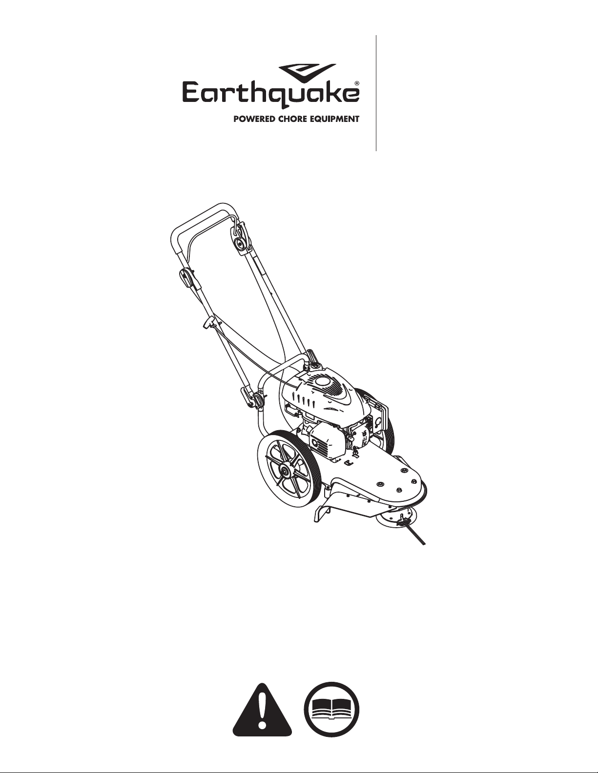
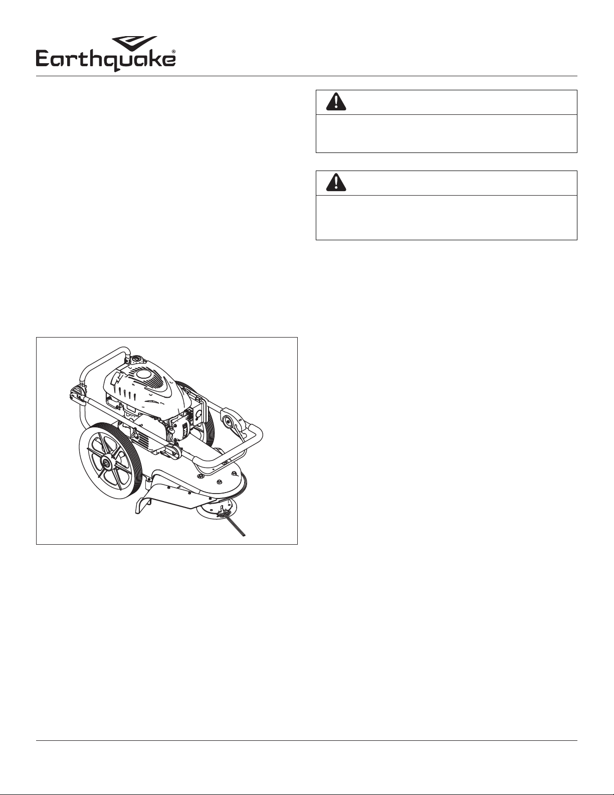
Trimmer Mower 600050 Series
SLOPE OPERATION
Slopes are a major factor related to slip and fall accidents which
can result in severe injury. All slopes require extra caution. If you
feel uneasy on a slope, do not trim it. Do trim across the face of
slopes; never up and down. Do not trim excessively steep slopes
(maximum 15 degrees) or areas where the ground is very rough.
See the “Slope Guide” in the back of this manual to check a slope.
Exercise extreme caution when changing direction on slopes.
Remove objects such as rocks, tree limbs, etc.
Watch for holes, ruts, or bumps.Tall grass can hide obstacles.
Do not trim near drop-offs, ditches, or embankments. The
operator could lose footing or balance.
Do not trim excessively steep slopes.
Do not trim on wet grass. Reduced footing could cause
slipping.
CHILDREN
Tragic accidents can occur if the operator is not alert to the
presence of children. Children are often attracted to the
trimmer and the trimming activity. Never assume that children
will remain where you last saw them.
care of a responsible adult.
Be alert and turn trimmer off if children enter the area.
Before and while moving backwards, look behind and down
for small children.
Never allow children to operate the trimmer.
or other objects that may obscure vision.
SERVICE
flammable and vapors are explosive.
Never remove gas cap or add fuel with the engine running.
Allow engine to cool before refueling. Do not smoke while
refueling.
Fill fuel tank outdoors with extreme care. Never fill fuel tank
indoors or near appliances with pilot lights, heaters, or other
ignition sources. Replace fuel cap securely. If fuel is spilled, do
not start the engine but move product and fuel container from
area. Clean up spilled fuel and allow to evaporate.
Never store the machine or fuel container inside where there
is an open flame (such as a water heater), or other ignition
source.
If the fuel has to be drained, this should be done outdoors.
The drained fuel should be stored in a container specifically
designed for fuel storage or it should be disposed of carefully.
• Engines give off carbon monoxide, an odorless, colorless,
poison gas. Breathing carbon monoxide can cause
nausea, fainting or death. Always start and run engine
outdoors. Do not start or run engine in an enclosed area,
even if doors or windows are open.
Never make adjustments or repairs with the engine (motor)
running. Disconnect the spark plug wire, and keep the wire
away from the plug to prevent accidental starting (remove
the ignition key if equipped with an electric start). Always
wear eye protection when you make adjustments or repairs.
Check the trimmer head and engine mounting bolts at
frequent intervals for proper tightness.
condition. Check mounting hardware on trimmer head every
time you change trimmer line and prior to each use.
Never tamper with safety devices. Check their proper
operation regularly.
When servicing or repairing the trimmer, do not tip the
machine over or up unless specifically instructed to do so
in this manual. Service and repair procedures can be done
with the trimmer in an upright position. Some procedures
will be easier if the machine is lifted on a raised platform or
working surface.
To reduce fire hazard, keep trimmer free of grass, leaves, or
other debris build-up. Clean up oil or fuel spillage. Allow
trimmer to cool before storing.
Stop and inspect the equipment if you strike an object.
Repair, if necessary, before restarting.
Always disconnect spark plug wire before cleaning, repairing,
or adjusting.
Do not change the engine governor setting or over-speed
the engine.
Clean and replace safety and instruction decals as necessary.
To guard against engine over-heating, always have engine
debris filter mounted and clean.
Inspect trimmer before storage.When not in use, disconnect
spark plug lead and store indoors in a dry place locked or
otherwise inaccessible to children.
parts.
Never replace the cutting lines with metal parts.
When storing gasoline or equipment with fuel in the tank,
store away from furnaces, stoves, water heaters or other
appliances that have a pilot light or other ignition source
because they can ignite gasoline vapors.