Areva KITZ 101 User manual

Type KITZ 101, 102
Interface Unit
User Manual
R8521J


User Manual
Type KITZ 101, 102
Interface Unit
HANDLING OF ELECTRONIC EQUIPMENT
A person's normal movements can easily generate electrostatic potentials of several thousand volts.
Discharge of these voltages into semiconductor devices when handling electronic circuits can cause serious
damage, which often may not be immediately apparent but the reliability of the circuit will have been
reduced.
The electronic circuits of AREVA T&D products are immune to the relevant levels of electrostatic discharge when
housed in their cases. Do not expose them to the risk of damage by withdrawing modules unnecessarily.
Each module incorporates the highest practicable protection for its semiconductor devices. However, if it becomes
necessary to withdraw a module, the following precautions should be taken to preserve the high reliability and
long life for which the equipment has been designed and manufactured.
1. Before removing a module, ensure that you are at the same electrostatic potential as the equipment by
touching the case.
2. Handle the module by its front-plate, frame, or edges of the printed circuit board.
Avoid touching the electronic components, printed circuit track or connectors.
3. Do not pass the module to any person without first ensuring that you are both at the same electrostatic
potential. Shaking hands achieves equipotential.
4. Place the module on an antistatic surface, or on a conducting surface which is at the same
potential as yourself.
5. Store or transport the module in a conductive bag.
More information on safe working procedures for all electronic equipment can be found in BS5783 and
IEC 147-0F.
If you are making measurements on the internal electronic circuitry of an equipment in service, it is preferable
that you are earthed to the case with a conductive wrist strap.
Wrist straps should have a resistance to ground between 500k – 10M ohms. If a wrist strap is not available,
you should maintain regular contact with the case to prevent the build up of static. Instrumentation which may
be used for making measurements should be earthed to the case whenever possible.
AREVA T&D strongly recommends that detailed investigations on the electronic circuitry, or modification work,
should be carried out in a Special Handling Area such as described in BS5783 or IEC 147-0F.

Page 4

Page 5
Contents
SAFETY SECTION 7
1. INTRODUCTION 11
2. HANDLING AND INSTALLATION 11
2.1 General considerations 11
2.2. Electrostatic discharge (ESD) 11
2.3. Unpacking 12
2.4. Storage 12
3. KITZ FEATURES 12
4. CONNECTION 13
4.1 RS232 (IEC-870) connection 17
4.2 K-Bus connection 18
5. KITZ OPTION SWITCHES 19
5.1 Option switch settings 20
5.2 Data rate selection 20
5.3 RS232 (IEC-870) frame parity 20
5.4 Time tagging of K-Bus messages 21
5.5 Modem control 21
6. KITZ LED INDICATIONS 22
7. PROTOCOL CONVERSION 23
7.1 Message format 23
7.2 Message validation 23
7.3 Message time-out 24
7.4 Conversion sequences 24
7.5 Receive message buffering 24
8. KITZ ADDITIONAL FEATURES 25
8.1 Real time clock (RTC) synchronisation 25
9. TECHNICAL DATA 26
9.1 Ratings – auxiliary supply 26
9.2 Burden – auxiliary supply 26
9.3 Fuse Ratings 26
9.4 Accuracy 26
9.5 Operation indicator 26
9.6 Communication ports 27
9.7 Message buffers 28
9.8 High voltage withstand 28
9.9 Environmental 29
9.10 Mechanical tests 29
9.11 Enclosure protection IEC529 IP20 29
10. COMMISSIONING 30
10.1 Commissioning preliminaries 30
10.2 Auxiliary supply tests 31
10.3 Settings 32

Page 6
11. PROBLEM SOLVING 32
11.1 Green supply indication led is off 32
11.2 Fuse blows on power-up (KITZ 101 only). 32
11.3 IEC 870 receive indication is off when communicating with a master station 32
11.4 K-Bus receive indication is off when communicating with a master station
(and K relay) 32
11.5 Slow communications response (many retries) 33
11.6 Real time clock corruption 33

Page 7
SAFETYSECTION
This Safety Section should be read before commencing any work on the equipment.
Health and safety
The information in the Safety Section of the product documentation is intended to
ensure that products are properly installed and handled in order to maintain
them in a safe condition. It is assumed that everyone who will be associated with
the equipment will be familiar with the contents of the Safety Section.
Explanation of symbols and labels
The meaning of symbols and labels which may be used on the equipment or in
the product documentation, is given below.
Caution: refer to product documentation Caution: risk of electric shock
Protective/safety *earth terminal
Functional *earth terminal.
Note: this symbol may also be used for a protective/
safety earth terminal if that terminal is part of a
terminal block or sub-assembly eg. power supply.
*Note: The term earth used throughout this manual is the direct equivalent of
the North American term ground.
Installing, Commissioning and Servicing
Equipmentconnections
Personnel undertaking installation, commissioning or servicing work on this
equipment should be aware of the correct working procedures to ensure safety.
The product documentation should be consulted before installing, commissioning
or servicing the equipment.
Terminals exposed during installation, commissioning and maintenance may
present a hazardous voltage unless the equipment is electrically isolated.
If there is unlocked access to the rear of the equipment, care should be taken by
all personnel to avoid electric shock or energy hazards.
Voltage and current connections should be made using insulated crimp
terminations to ensure that terminal block insulation requirements are maintained
for safety. To ensure that wires are correctly terminated, the correct crimp
terminal and tool for the wire size should be used.

Page 8
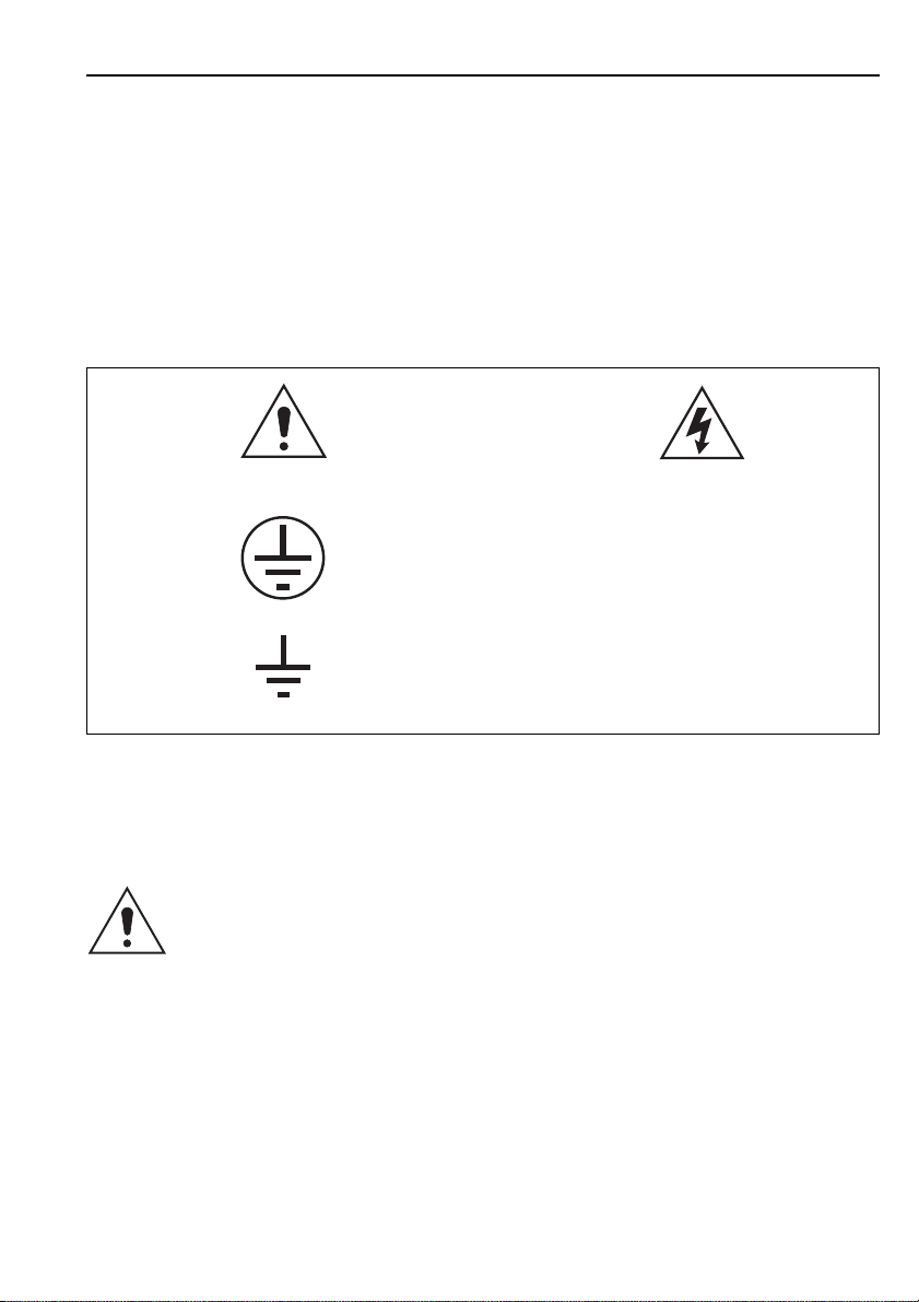
Before energising the equipment it must be earthed using the protective earth
terminal, or the appropriate termination of the supply plug in the case of plug
connected equipment. Omitting or disconnecting the equipment earth may cause
a safety hazard.
The recommended minimum earth wire size is 2.5 mm2, unless otherwise stated
in the technical data section of the Service Manual.
Before energising the equipment, the following should be checked:
Voltage rating and polarity;
CT circuit rating and integrity of connections;
Protective fuse rating;
Integrity of earth connection (
where applicable
)
Equipment operating conditions
The equipment should be operated within the specified electrical and
environmental limits.
Current transformer circuits
Do not open the secondary circuit of a live CT since the high voltage produced
may be lethal to personnel and could damage insulation.
External resistors
Where external resistors are fitted to relays, these may present a risk of electric
shock or burns, if touched.
Battery replacement
Where internal batteries are fitted they should be replaced with the
recommended type and be installed with the correct polarity, to avoid possible
damage to the equipment.
Insulation and dielectric strength testing
Insulation testing may leave capacitors charged up to a hazardous voltage. At
the end of each part of the test, the voltage should be gradually reduced to zero,
to discharge capacitors, before the test leads are disconnected.
Insertion of modules and pcb cards
These must not be inserted into or withdrawn from equipment whilst it is
energised, since this may result in damage.
Fibre optic communication
Where fibre optic communication devices are fitted, these should not be viewed
directly. Optical power meters should be used to determine the operation or
signal level of the device.

Page 9
Older products
Electrical adjustments
Equipments which require direct physical adjustments to their operating
mechanism to change current or voltage settings, should have the electrical
power removed before making the change, to avoid any risk of electric shock.
Mechanical adjustments
The electrical power to the relay contacts should be removed before checking
any mechanical settings, to avoid any risk of electric shock.
Draw out case relays
Removal of the cover on equipment incorporating electromechanical operating
elements, may expose hazardous live parts such as relay contacts.
Insertion and withdrawal of extender cards
When using an extender card, this should not be inserted or withdrawn from the
equipment whilst it is energised. This is to avoid possible shock or damage
hazards. Hazardous live voltages may be accessible on the extender card.
Insertion and withdrawal of heavy current test plugs
When using a heavy current test plug, CT shorting links must be in place before
insertion or removal, to avoid potentially lethal voltages.
Decommissioning and Disposal
Decommissioning: The auxiliary supply circuit in the relay may include
capacitors across the supply or to earth. To avoid electric
shock or energy hazards, after completely isolating the
supplies to the relay (both poles of any dc supply), the
capacitors should be safely discharged via the external
terminals prior to decommissioning.
Disposal: It is recommended that incineration and disposal to water
courses is avoided. The product should be disposed of in a
safe manner. Any products containing batteries should have
them removed before disposal, taking precautions to avoid
short circuits. Particular regulations within the country of
operation, may apply to the disposal of lithium batteries.

Page 10
Technical Specifications
Protective fuse rating
Refer to Section 9 Technical Data, item 9.3 Fuse ratings
Insulation class: IEC 1010-1: 1990/A2: 1995 This equipment requires a
Class I protective (safety) earth
EN 61010-1: 1993/A2: 1995 connection to ensure user
Class I safety.
Installation IEC 1010-1: 1990/A2: 1995 Distribution level, fixed
Category Category III installation. Equipment in
(Overvoltage): EN 61010-1: 1993/A2: 1995 this category is
Category III qualification tested at 5kV
peak, 1.2/50µs, 500ý,
0.5J, between all supply
circuits and earth and also
between independent
circuits.
Environment: IEC 1010-1: 1990/A2: 1995 Compliance is
Pollution degree 2 demonstrated by reference
EN 61010-1: 1993/A2: 1995 to generic safety standards.
Pollution degree 2
Product safety: 73/23/EEC Compliance with the
European Commission
Low Voltage Directive.
EN 61010-1: 1993/A2: 1995 Compliance is demonstrated
EN 60950: 1992/A3: 1995 by reference to generic safety
standards.

Page 11
Section 1. INTRODUCTION
The K-Bus communication system was developed to allow connection of remote
K Range units (slaves) to a central point of access (a master control unit eg. a PC
and a KITZ unit), thus allowing remote control and monitoring functions to be
performed using an appropriate communication language. The system was
initially developed for use in the electrical supply industry at distribution voltage
levels, but can equally be applied to other voltage levels or indeed to other
systems which would benefit from such a communication system.
This document details the KITZ interface unit used in conjunction with
AREVA T&D K Range protection relays. It describes the operation and features of
the unit in sufficient detail to allow users to interface this unit to other devices
(PCs or MODEMS).
This guide should be used in conjunction with the service manual of the
equipment with which the KITZ is to be interfaced.
The unit allows conversion between the K-Bus data format and IEC-870 - 5 FT
1.2. data format. This enables (for example) a PC based master station to
communicate with K Range units (relays).
Section 2. HANDLINGAND INSTALLATION
2.1 General considerations
2.1.1 Receipt of KITZ units
Although the KITZ interface unit is of a generally robust construction, the unit
requires careful treatment prior to use on site. Upon receipt, the unit should be
examined immediately, to ensure no damage has been sustained in transit.
If damage has been sustained during transit, a claim should be made to the
transport contractor, and an AREVA T&D representative should be promptly
notified.
2.2. Electrostatic discharge (ESD)
The KITZ unit uses components that are sensitive to electrostatic discharges.
The electronic circuits are well protected by the metal case and the internal
components should not be exposed by removal of the top or front of the case.
There are no user setting adjustments within the unit.
A person’s normal movements can easily generate electrostatic potentials of
several thousand volts. Discharge of these voltages into semiconductor devices
when handling electronic circuits can cause serious damage, which often may
not be immediately apparent but the reliability of the circuit will have been
reduced.
When transporting the unit, care should be taken so that the RS232 port is not
subjected to ESD. Touching the case will ensure you are at the same electrostatic
potential as the unit.

Page 12
If you are making measurements on the internal electronic circuitry of an
equipment in service, it is preferable that you are earthed to the case with a
conductive wrist strap. Wrist straps should have a resistance to ground between
500k-10M ohms. If a wrist strap is not available, you should maintain regular
contact with the case to prevent a build-up of static. Instrumentation which may
be used for making measurements should be earthed to the case whenever
possible.
More information on safe working procedures for all electronic equipment can
be found in BS 5783 and IEC 147-OF. It is strongly recommended that detailed
investigations on electronic circuitry, or modification work, should be carried out
in a Special Handling Area such as described in the above-mentioned BS and
IEC documents.
2.3. Unpacking
Care must be taken when unpacking and installing the unit to prevent damage.
2.4. Storage
If the KITZ unit is not to be installed immediately upon receipt it should be stored
in a place free from dust and moisture in the original carton. Where de-
humidifier bags have been included in the packing they should be retained.
The action of the de-humidifier crystals will be impaired if the bag has been
exposed to ambient conditions and may be restored by gently heating the bag
for about an hour, prior to replacing it in the carton.
Dust which collects on a carton may, on subsequent unpacking, find its way into
the unit; in damp conditions the carton and packing may become impregnated
with moisture and the de-humidifier will lose its efficiency.
Storage temperature –25°C to +70°C.
Section 3. KITZ FEATURES
The protocol converter features are as follows:
Choice of desktop (KITZ 101) or back of panel mounting (KITZ 102).
Wide range of auxiliary supply inputs.
Enables K-Bus to be interfaced with standard IEC 870-5 FT1.2 communication
links.
Converts K-Bus messages to IEC-870 format.
Converts IEC-870 messages to K-Bus format.
Allows alternative data communication rates and frame format on the
IEC-870 port.
Optionally adds a time tag to K Range reply messages.
Buffers incoming messages thus allowing transmission at lower speed.
Allows synchronisation of the real time clock via the communications.
Provides visual indication of communication operation.

Page 13
Section 4. CONNECTION
A typical application connection arrangement for the KITZ 101 is shown below:
Figure 1a: Typical application of KITZ 101 interface unit.
KBUS
1
2
KBUS
1
2
PC
K Range relays
K-Bus to IEC 870 interface
(KITZ 101)
RS232 link
serial port
Mains cable
K-Bus
to terminals 1 & 2
screen to
Connection to K-Bus
Detail of earth link
& external resistor when fitted

Page 14
Figure 1b: Typical application of KITZ 102 interface unit.
KBUS
1
2
PC
K Range relays
K-Bus to IEC 870 interface
(KITZ 102)
RS232 link
serial port
Auxiliary supply
K-Bus
to terminals 1 & 2
screen to
Connection to K-Bus
Detail of earth link
& external resistor when fitted
KBUS
1
2

Page 15
A schematic representation of a typical application connection arrangement is
shown below:
Figure 2a: KITZ 101 IEC-870 (RS232) port to PC serial port connections.
L
N
2 TX
3 RX
7 Signal ground
1 Protective ground
KITZ 101
K-Bus/IEC870 Interface
21
* 150R
IBM or compatible PC
(for pin assignment numbers
see table 1)
Typical
K Range
Relay
* 150R
54
54
54
56 56 56
*2 off externally mounted resistor
assemblies FT 0113 001 supplied with
K-Bus/IEC870 interface
Screen Link
Terminals
All points are
internally connected
Typical
K Range
Relay
Typical
K Range
Relay

Page 16
Figure 2b: KITZ 102 IEC-870 (RS232) port to PC serial port connections.
2 TX
3 RX
7 Signal ground
1 Protective ground
KITZ 102
K-Bus/IEC870 Interface
21
*
150R
IBM or compatible PC
(for pin assignment numbers
see table 1)
Typical
K Range
Relay
* 150R
54
54
54
56 56 56
*2 off externally mounted resistor
assemblies FT 0113 001 supplied with
K-Bus/IEC870 interface
Screen Link
Terminals
All points are
internally connected
Typical
K Range
Relay
Typical
K Range
Relay
Auxiliary supply
dc voltage

Page 17
4.1 RS232 (IEC-870) connection
4.1.1 Recommended cable
A standard PC serial port interface cable (with the connections listed in Table 1)
should be used. It is essential that the cable screen is earthed at one end to
ensure adequate screening. The connectors should be screw-locked to the KITZ
and the PC.
4.1.2 Cable length
The maximum recommended length of cable from the IEC-870 Communications
port is 15 metres (50 feet) or 2500 pF total cable capacitance. For longer
distance communication on the IEC-870 port an external RS485 interface may
be required.
4.1.3 Data rates
The maximum data communication rate specified in the RS232-c standard is
20 kbits/s. The KITZ unit will support faster communication data rates (up to
115.2 kbits/s) for use with development tools such as K-Spy.
The following table shows the connections required to interface a KITZ to a user
PC serial data port. These connections are for guidance only and reference
should be made to the PC user manual.
Note that the terms “Receive Data” and “Transmit Data” (in Tables 1 and 2)
refer to the named connector and not to a nominated end.
KITZ PC-at laptop PC or PS/2 Type
25 Pin ‘D’ male 9 Pin ‘D’ male 25 Pin ‘D’ male
connector (DTE) connector (DTE) connector (DTE)
1 – Protective Ground No Connection 1 – Protective Ground
See note
2 – Transmit Data 2 – Receive Data 3 – Receive Data
3 – Receive Data 3 – Transmit Data 2 – Transmit Data
7 – Signal Common 5 – Signal Common 7 – Signal Common
Connector Shell to
Cable Screen (see note)
Table 1 KITZ/PC RS232 port inter-connections.
Note: The RS232 cable screen should be connected to earth at one end only,
to prevent earth loops.
Pin 7 (Signal Common) or Pin 1 (Protective Ground) can be used as
an alternative to the Connector Shell.

Page 18
The following table lists the complete (Modem Control) pin functions of the
KITZ and the PC:
Pin KITZ (DTE) PC AT LAPTOP PC or PS/2 Type
No Connector 9 Pin female connector 25 Pin male connector
(DTE) (DTE)
1 Protective Ground Carrier Detect (CD) Protective Ground
2 Transmit Data (Tx) Receive Data (Rx) Transmit Data (Tx)
3 Receive Data (Rx) Transmit Data (Tx) Receive Data (Rx)
4 Request To Send Data Terminal Ready Request To Send
(RTS) (DTR) (RTS)
5 Clear To Send (CTS) Signal Common Clear To Send (CTS)
6 Data Set Ready (DSR) Data Set Ready (DSR) Data Set Ready (DSR)
7 Signal Common Request To Send (RTS) Signal Common
8 Carrier Detect (CD) Clear To Send (CTS) Carrier Detect (CD)
9 Ring Indicator (RI)
20 Data Terminal Ready Data Terminal Ready
(DTR) (DTR)
22 Ring Indicator (RI)
Table 2 KITZ and PC RS232 port modem control connections.
4.2 K-Bus connection
4.2.1 Recommended cable
Twisted pair of wires with outer screen, to DEF STANDARD 16-2-2c 16 Strands
of 0.2mm diameter, 40mý per metre per core, 171pF per metre (core to core),
288pF per metre (core to screen).
4.2.2 Connection method
K-Bus is a multi-drop standard. The K-Bus cable extends from a KITZ interface unit
and is daisy-chained from one slave device to the next in a radial fashion. The
total K-Bus cable from the master control unit to the farthest slave device is known
as a spur. No branches may be made from the spur.
4.2.3 Cable termination
Four millimetre looped screw termination or fast-on connection (as per MIDOS
standard terminations). The outer screen should be earthed at one point of the
cable only, preferably at the connection to the KITZ unit. The transmission wires
should be terminated using a 150ý resistor at both extreme ends of the cable.
4.2.4 Cable polarity
Polarisation is not necessary for the 2 twisted wires.

Page 19
4.2.5 Maximum cable (spur) length
The maximum cable length is 1000m.
4.2.6 Maximum slave devices per spur
The maximum number of devices per spur is 32.
Section 5. KITZ OPTION SWITCHES
SC
N
K-Bus TO IEC 870 INTERF
ACE
F
F
KITZ 1
01
7
K-B
us
Rx
Tx
IE
C
870
Rx
Tx
OPTIO
NS
2
0
1
1
4
K-B
us
12
No
Vx
V~
Figure 3a: KITZ 101 front plate layout and rear connections.
7
OPTIO
N
S
2
0
1
1
4
K-Bus TO IEC 870 INTERF
ACE
F
F
KITZ 1
02
K-B
us
Rx
Tx
IE
C
870
Rx
Tx
SCN
K-B
us
1
2
No
Vx
V
A
U
XILIA
R
Y
SUPPL
Y
L
L
VO
LT
AGE
T
T
Figure 3b: KITZ 102 front plate layout and rear connections.

Page 20
5.1 Option switch settings
The option switches on the KITZ front plate allow the user to configure the KITZ
to suit the application requirements.
The following table lists the KITZ option switch functions.
Switch No. Function
0 to 2 RS232 (IEC-870) data rate selection
3 RS232 (IEC-870) frame format
4 Add IEC time tag to K-Bus message
5 Modem present
6 Modem set-up
7 Reserved
Table 3. KITZ option switch functions.
A switch function is operational when in the UP position (marked 1). The switch
position at power-up determines which features are enabled (or settings apply).
Any changes made to the switch positions while the supply is present will not
affect the operation.
5.2 Data rate selection
The three left-hand switches (switches 0 to 2) control the KITZ IEC-870 (RS232)
port data communication rate setting.
The RS232 port is capable of supporting asynchronous serial communication at
the data rates specified in Table 4. The corresponding switch settings are also
shown in the table.
Data Rate Switch 0 Switch 1 Switch 2
1200 Position 0 Position 0 Position 0
2400 Position 1 Position 0 Position 0
4800 Position 0 Position 1 Position 0
9600 Position 1 Position 1 Position 0
19200 Position 0 Position 0 Position 1
38400 Position 1 Position 0 Position 1
57600 Position 0 Position 1 Position 1
115200 Position 1 Position 1 Position 1
Table 4. KITZ IEC-870 (RS232) Port data rate selection.
5.3 RS232 (IEC-870) frame parity
The fourth switch (switch 3) allows the frame format of the RS232 (IEC-870)
communications port to be set to the following modes:
Position 0 Asynchronous 11 bit (1 start bit, 8 data bits, 1 parity, 1 stop bit)
Position 1 Asynchronous 10 bit (1 start bit, 8 data bits, no parity, 1 stop bit)
This manual suits for next models
1
Table of contents