Thermionic Culture Nightingale 2 User manual

©Thermionic Culture Ltd., August 2014 1
WARNING
For your personal safety, please read this operating manual and
warning thoroughly before using the equipment.
This unit must be installed in such a manner that operator access
to the mains plug is maintained. Where the product is to be rack
mounted, this may be achieved by having access to the
disconnection device for the whole rack.
To reduce the risk of electric shock, it is essential that the unit is
disconnected from the mains supply before removing the covers.
In the event that this unit has been dropped or has suffered an
impact, an electrical safety test must be carried out before
reconnection to the mains supply.
This equipment is not intended for use in explosion hazard
environments. It must be used and stored such that the ambient
relative humidity does not exceed 80%, nor is the temperature to
be allowed to drop to a level which would cause dew point to be
reached.
Please ensure that adequate ventilation is provided and that the
ventilation slots are not obstructed. When rack mounting this
equipment a space of 1U should be left above it for air flow, and/or
a fan may be required to provide sufficient airflow to dissipate the
heat of the valves and not affect any equipment mounted above it
.
It is not advisable to operate this equipment if all valves are not in
place and working, as voltages will rise and components may
overheat and fail.

©Thermionic Culture Ltd., August 2014 2
CONTENTS
Section Page
1 Introduction 3
2 Installation/ Starting up 5
3 Controls and Operation - Preamp A and B 7
3.1 Input Level 7
3.2 Gain 7
3.3 Top 7
3.4 Pres 7
3.5 Bass 7
3.6 Top Cut 8
3.7 Phase 8
3.8 Bass Cut 8
3.9 HPF 8
3.10 EQ Bypass 9
4 Controls and Operation – I/P Select 10
5 Controls and Operation – Compressor 11
5.1 Meter 11
5.2 Threshold 11
5.3 Release 11
5.4 Comp Gain 12
5.5 O/P Level 12
6 Operational Hints 13
7 Servicing…. Valves / Tubes 15
8 Specification 16

©Thermionic Culture Ltd August 2014 3
1Introduction
The Nightingale 2 is an improved version of the original
Nightingale.
It now incorporates a useful eq bypass switch for
comparison purposes in Input channels A & B. There is also
a Standby switch which when activated reduces the high
tension voltage to all of the valves. Use of this will prolong
valve life and should be used when first switching on and at
any time that the unit is standing idle with mains supply on.
The Nightingale 2 comes in exactly the same 4U ½ rack
format with detachable power supply and can be used either
stand-alone due to its robust construction, or mounted in a
standard 19 inch rack using our rack mount kit. It can be on
its own or share the space with another unit in this range.
The Nightingale uniquely comprises 3 different components.
There are 2 (A and B) mic. / line preamps which also have
EQ, filters, phase adjustment, 48V phantom power and a
front panel DI input.
There is one mono compressor that is a modified version of
the Phoenix, one of Thermionic Culture’s oldest and most
popular designs.
We have provided front panel switching to allow the user to
configure the Nightingale 2 in different modes. The
components can all be used separately or they can be linked
and summed together internally via the front panel control.
Each preamp has a transformer balanced input, transformer-
less unbalanced output and uses 1 valve per channel. The
valve is an ECC832. The valves are run in a single ended
configuration, which we feel gives a good balance between
smoothness, clarity and harmonic distortion.
The EQ circuit is an active design, which is similar in
operation to that found in the Earlybird 2 mic. preamps.

©Thermionic Culture Ltd August 2014 4
The mono compressor is a variation of the Phoenix design,
which uses a different input transformer and valve
complement. There is a different detector valve (5726),
compression valve (6AQ8) and output valve (5965). This
gives a harder type of compression curve, which starts at
less than 2:1 and ends up as a 20:1 ratio at high
compression levels. The combination of new valves and
transformers also gives the unit more available gain. We find
that these qualities suit what this unit as a whole is capable
of.
We feel that The Nightingale 2 is a very versatile and unique
unit. The ability to take 2 different signals from DI, mic. or
line sources then be able to EQ, compress and internally
sum them together whilst retaining the ability to use all 3
components individually, or any combination in between, is a
very creative combination of features that can’t be found in
any other single unit of this size.
The quality of the circuit design means that the sound of the
unit stays open and natural even when applying extreme
amounts of processing. Full use of all the features can be
made without fear of seriously damaging the signal quality.
It was originally made for Live use where 2 vocal mics may
be combined, each with its own eq,, into 1 “soft knee””
compressor, with phase reversal on one mic to reduce band
pick-up.

©Thermionic Culture Ltd August 2014 5
2Installation / Starting up
The Nightingale 2 can be operated in almost any
environment, for studio or live use.
We supply on request a special Rack, capable of holding 2
units.
If 2 units are rack-mounted with other equipment above
them, we strongly advise that a gap of 1 U is left above so
that heat can dissipate, and/or use a fan.
When used in a rack, the power supply can be detached,
moved further back and re-connected using a special cable.
This is certainly not essential, but can reduce the low
frequency hum by up to 2 dB.
We are considering producing an external PSU capable of
powering up to 6 units. Please contact us if this interests
you.
All connectors, except DIs, are standard XLRs with pin 1
ground and pins 2 & 3 Line (pin 2 “hot”).
Connections to other equipment should be made using
standard twin screened cables.
Cable length should not be an issue, within reason.
DI inputs are unbalanced jacks so cables must be shorter,
and we recommend 3 m max unless the source impedance
is low as with most synthesisers, but beware of “hum loops”.
Before switching on check that the mains selector is set for
your local supply.230 for 220-240v, 115 for 110-120v. We
factory set these for the ordered destination, but if it’s set
incorrectly you may need to change the fuse. Your local
dealer should carry spares. See table at end of manual.
Now check that the Standby switch is set in the Standby
position. Use the Standby facility when switching on from
cold and if the unit is powered up but not actually in use.

©Thermionic Culture Ltd August 2014 6
This will prolong valve life and keep heat and power
consumption lower.
Switch on. The power switch is at the rear under the mains
inlet. The compression meter will rise to about ½ way. Now
switch out Standby and the meter will go to 0. If it ends up
not quite vertical, use the adjustment tool provided to set to 0
using the zero adjust facility on the back. It will drift a little
with mains supply variations. It’s not critical that the meter
reads exactly zero (with no signal) as it’s just an indication of
the compression.
Do not adjust the little screw on the front of the meter. This
just changes the angle of the needle when the unit is cold,
when it should be horizontal.
If you are using 1 or 2 microphones that require Phantom
Power, switch on the 48v switch on the front panel. This is
activated by pulling on it before switching down. It applies
48v to both mic channels but power is disabled when the
input selector is in Line mode on the individual channel.
You are now ready to go, so read the next sections!

©Thermionic Culture Ltd August 2014 7
3Controls and Operation - Preamp A and B
3.1 Input Level
This 3 way switch at the top of each preamp section
allows the user to run the preamp as a Line input, Hi
mic. level input or Lo mic. level input.
3.2 Gain
The rotary gain control is located at the top of each
preamp section. It allows the channel signal to be
attenuated at the input continuously. This gives a
channel gain between:-
-∞to + 5 dB gain for the Line amp
-∞to + 21 dB gain for the Hi mic. setting
-∞to + 34 dB gain for the Lo mic. setting
3.3 Top
The rotary control allows the amount of top lift EQ to
be continuously adjusted between 0 and +12 dB. The
EQ starts as a gentle type curve and it reaches it’s
peak at 9.5 kHz.
3.4 Pres
The rotary control allows the amount of mid lift EQ to
be continuously adjusted from 0 to +11dB with a very
broad curve peaking at 2.8kHz.
3.5 Bass
The rotary control allows the amount of bass lift EQ to
be continuously adjusted between 0 and +11 dB. The
EQ has a 'varislope' type curve which is initially very
broad, reaching a small peak at 90Hz at a position of
'5' and then reaches it’s final peak at 40Hz when the
control is turned on full.

©Thermionic Culture Ltd August 2014 8
3.6 Top Cut
The 3 position top cut switch gives 2 choices of filter at
high frequencies:-
Position 1 gives a flat response with no filter in circuit.
Position 2 gives a low pass filter 6dB down at 8 kHz
Position 3 gives a shelving type cut flattening out 8dB
down at 8 kHz
3.7 Phase
The phase switch is a 2 position switch and allows the
user to change the phase of the channel signal by
180º
3.8 Bass Cut
The bass cut switch is a 3 position switch which gives
2 choices of shelving filter at low frequencies. The
shelving filters are shallow types of bass cut and are
designed to interact with the bass lift to make a
simultaneous low mid cut and low bass lift possible.
Position 1 gives a flat response
Position 2 gives a shelving filter with a 3dB cut at
200Hz down to 7dB at 80 Hz
Position 3 gives a shelving fliter with a 3dB cut at
800Hz down to 6dB at 200Hz.
3.9 HPF
The high pass filter switch gives the user a filter which
is 6dB down at either 30Hz or 80Hz and becomes
more severe as the frequency drops.
These frequencies and filter slope work very well in
conjunction with the Bass control. Effectively allowing
the user to simply remove problem frequencies from a
sound or to allow the bass frequencies to be
dramatically enhanced without any danger of

©Thermionic Culture Ltd August 2014 9
producing sub bass frequencies that interfere with the
action of loudspeakers.
3.10 EQ Bypass
This switch cuts out all eqs and enables the user to
compare their effect.

©Thermionic Culture Ltd., August 2014 10
4 Controls and Operation - I/P Select
The 4 position 'I/P select' switch controls the most unique
feature of the Nightingale.
With 'I/P select' set to 'Line' the input to the compressor is
taken from the 'comp in' XLR socket located on the back of
the Nightingale.
With 'I/P select' set to 'A' the input to the compressor is taken
internally within the unit from the output of preamp A. The
preamp can be working at any setting and its signal will be
sent to the compressor.
The preamp signal will also continue to be sent to the
'preamp A output' XLR plug found on the back of the
Nightingale.
With 'I/P select' set to 'B' the input to the compressor is taken
from preamp B. This works exactly as described for preamp
A above.
With 'I/P select' set to 'A+B' the compressor takes its input
from an internally summed combination of outputs from
preamps A and B.
The mix between the 2 preamps can be adjusted by
changing their input gain settings. The 2 preamps can be set
in any configuration of mic, line or DI input. The signals from
the 2 preamps will still be sent to their respective XLR output
plugs. This makes it possible to use the unit for the following:
a) Individual use of 2 preamps and one compressor.;
b) One preamp plus compression and one preamp with no
compression;.
c) Summing any combination of 2 mic. , DI & line signals;
d) Recording 'clean' un-summed or compressed versions of
each preamp signal simultaneously to the processed
signal.;
e) Parallel processing.;
f) Extra mic. / DI signal gain.

©Thermionic Culture Ltd., August 2014 11
5 Controls and Operation - Compressor
5.1 Meter
This meter has the same function as the meters in a
standard Phoenix compressor. It allows the user to
read the amount of compression applied to the signal
in dBs. The ballistics of the meter are slower in action
than the actual compression in order for the user to
more easily see what level of compression is being
applied.
5.2 Threshold
This 4 way switch gives the user control over the
signal level at which compression begins. The 4
positions go from 'off' (no compression applied),
through 1,2 and 3. The position 3 is maximum
threshold and would be the equivalent of a setting of
'1' on the standard Phoenix. This gives maximum
possible compression.
5.3 Release
This 3 way switch controls the speed of recovery from
compression. The equivalent settings on a standard
Phoenix would be:-
Position F – setting of '1' - 60ms
Position M – setting of '3' - 150ms
Position S – setting of '7' - 500ms
It’s worth noting in this section that this compressor
has a fixed attack time.
This attack time is set at around the equivalent of a
setting of '4' on a standard Phoenix which gives a time
figure of 60ms.

©Thermionic Culture Ltd., August 2014 12
5.4 Comp Gain
This rotary indented control provides the adjustment
needed to the input gain of the compressor. This
version of the Phoenix circuit gives slightly more gain (
28 dB) than that found in the standard Phoenix
(26dB). This comes in useful when more gain may be
needed with a low mic. input signal level. The mic.
pre-amp may be sent to the compressor with the I/P
select switch and the compressor will add gain to the
mic. preamp giving a total gain of almost 60dB (3dB
less . in A+B mode).
5.5 O/P Level
This 5 way switch gives control over the final output
level of the compressor.
It acts as an attenuator at the final output of the unit.
So the cleanest signal possible can be obtained with
the switch set to 'MAX'. This gives zero signal
attenuation. The steps '3 , 2 , 1 and MIN' give
progressively more attenuation ( about 3.5 dB per
step) to the output signal should it be required.

©Thermionic Culture Ltd., August 2014 13
6 Operational Hints
You may find that the Nightingale can allow you to try any
combination of preamp, EQ and compression very quickly.
The following situations are some examples of where the
Nightingale is well suited to the task.
1) Snare drums and toms are often recorded with top and
bottom mics. This can result in many tracks getting recorded
which can clutter up a multitrack recording, especially when
working on tape or with limited numbers of A/D converters.
The Nightingale can be used with preamp A&B summed to
the compressor to present the user with a combined single
track, which may be compressed if desired. Don’t forget to
use the phase switch on the preamp for the underneath mic.
to reverse the phase!
2) A guitar amp, acoustic guitar or vocal is often mic’d with 2
mics for a combination of their sound qualities. This can be
EQ’d, summed and compressed on the spot. The individual
mics can still be recorded for safety.
3) It’s possible to record an instrument direct to multitrack
via one preamp and then combine the direct mic. with an
ambient mic, compressed heavily onto another track.
Panning these signals gives an unusual stereo effect where
the ambience is never overpowering the direct sound.
4) During mixing the Nightingale may be used to take 2 line
signals which may be EQ’d and compressed together. The
output from the pre- amps and compressor can be used in
parallel to make the most use out of the extreme
compression available in the unit.
5) A dynamic. signal that also has some ambience may be
fed into both preamps of the Nightingale. One preamp may
be put out of phase with the other and then both can be
summed into the compressor. Use of EQ can cause
differences between the signals to cause less than 180º
perfect cancellation, which can be compressed and this can
bring out some new dimensions to the existing sound.

©Thermionic Culture Ltd August 2014 14
6) In a Live situation where there are 2 vocalists The
Nightingale will blend the 2 together making them sound
warmer yet clearer and more cohesive. It improves the PA
sound. As soon as 1 vocalist starts singing the level of the
other mic. falls as well giving better separation and therefore
a cleaner band sound.

©Thermionic Culture Ltd., August 2014 15
7 Servicing / Valves / Tubes
In the unlikely event of a fault contact your local Authorised
Dealer or Thermionic Culture Ltd.
All Valves are guaranteed for 12 months but they tend to be the
most likely cause of any problems.
The valves are:-
Pre Amp
1 x 12DW7 (ECC 832) per channel.
Compressor
1 x 6AQ8
1 x 5726 (6AL5)
1 x 5965
If the unit is under warranty, do not remove any covers without
express permission from Thermionic Culture Ltd – otherwise the
warranty will be invalidated

©Thermionic Culture Ltd August 2014 16
8 Specification
Preamps
A & B
Compressor
Input Impedance
Mic Lo
Mic Hi
Line
600Ω
1200Ω
10kΩ
N/A
N/A
10kΩ
Output Impedance <400Ω<600
MOL (into 10kΩ) +26dBu +26dBu
Distortion (1kHz) 0.1% 0.02% *
Frequency Response
+0/-1 dB <10-35kHz 13-80kHz
Total Noise (unweighted
30kHz filter) below MOL 103dB 105dB
Max Gain 34dB 28dB
Phantom Power +48V N/A
* Increases with compression to a typical figure of 0.2% with
6dB compression.
The Nightingale can be set to operate from either 230V or
115V 50/60 Hz AC. The appropriate mains input voltage can
be selected on the red switch located next to the mains inlet.
Note: Mains fuses must be replaced in accordance with the
following table.
Mains Voltage Fuse Rating
230V T315mA
115V T630mA
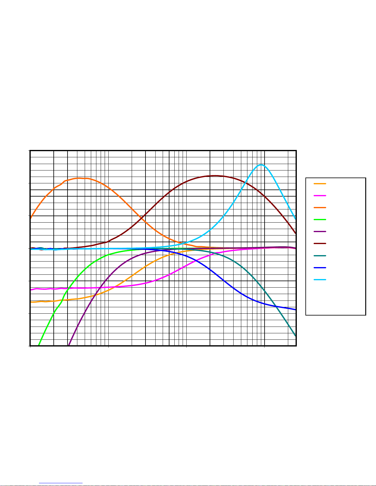
The Nightingale - Frequency Response Curves
-15
-10
-5
0
5
10
15
01 2511.010.0
Frequency (kHz)
Gain (dB)
Bass Cut 1
Bass Cut 2
Bass Lift
HPF 30Hz
HPF 80Hz
Presence
Top Cut 1
Top Cut 2
Top Lift
Presence, Bass
Lift & Top Lift all
measured at Max.
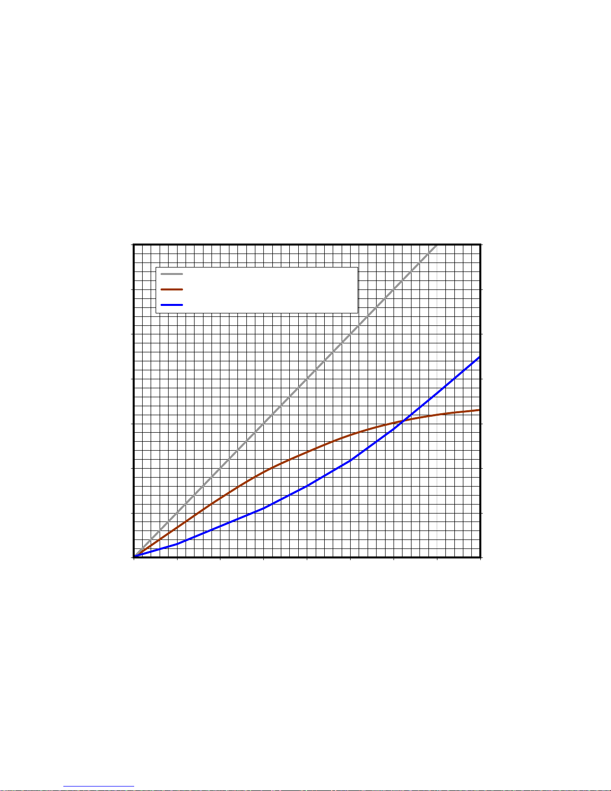
The Nightingale - Compression
-20
-15
-10
-5
0
5
10
15
-20 -15 -10 -5 0 5 10 15 20
Input Level
Output dB
0
5
10
15
20
25
30
35
Compression dB
Output dB (max. compression)
Output dB (no compression)
Compression dB (max. compression)

Thermionic Culture Ltd., Harlow, Essex, UK
Tel: +44 (0)1279 414 770
www.thermionicculture.com
Table of contents
Other Thermionic Culture Recording Equipment manuals


Popular Recording Equipment manuals by other brands


Brainworx
Brainworx Engl Savage 120 Plugin Manual

Sanyo
Sanyo VHR-850 Service manual

Sound Devices
Sound Devices 788T user guide

Quadelectra
Quadelectra QASIC RZ-i Operation manual

Innovative Technology
Innovative Technology ITRR-501 instructions

PS Engineering
PS Engineering PMA8000G System installation and operation manual


