arexTek TR3800 User manual


1
Chapter 1 General Information...................................................................4
1.1 Introduction......................................................................................4
1.2 Hardware Specifications..................................................................6
1.3 Appearance Illustration And Status Keys.........................................8
Chapter 2 Hardware Installation.................................................................9
2.1 Hardware Requirements................................................................10
2.2 How To Read The ID Card.............................................................11
2.3 How To Settle The Machine...........................................................12
2.4 Internal Connectors of TR3800......................................................14
2.6 Link Modes.....................................................................................16
2.7 LCD Display And External Alarm/Access Controller......................19
2.8 Keypad Settings.............................................................................20
Chapter 3 Software Installation................................................................23
3.1 Communication Wizard Installation ...............................................23
3.2 Copyright Declaration....................................................................25
3.3 Getting Started...............................................................................26
Chapter 4 System Settings And Windows Scheduled Task.....................28
4.1 Communication..............................................................................28
4.1.1 Connection type........................................................................28
4.2 Caption...........................................................................................30
4.2.1 TR-Caption................................................................................30
4.2.2 Shift Alias ..................................................................................30
4.2.3 Status Alias................................................................................31
4.2.4 The Interaction between Caption/Alias and Other Functions...31

2
4.3 Trancard File Edition......................................................................32
4.4 Record’s Format ............................................................................33
4.5 Extras.............................................................................................34
Chapter 5 Records Saving And Excel CSV Output..................................35
Chapter 6 Time-Recorder Settings ..........................................................37
6.1 TR Settings and Clock Synchronization........................................37
6.1.1 Time-Recorder Panel................................................................37
6.1.2 Set Time-Recorders’ Date/Time................................................37
6.1.3 Auto Synchronization ................................................................38
6.1.4 Advanced Settings ...................................................................38
6.2 Alarm Time ....................................................................................40
6.3 Shift Time ......................................................................................41
6.3.1 Shift Mode.................................................................................41
6.4 Access Control ..............................................................................44
6.4.1 Memory Disposal ......................................................................46
6.4.2 How to Use Wild Card Edition...................................................46
Chapter 7 Real-time Monitor....................................................................47
7.1 Staff File Edition.............................................................................48
7.2 Real-time Monitor And Record Saving ..........................................50
7.3 Real-time Monitor Via Modem.......................................................51
Chapter 8 Scan Time-Recorders..............................................................52
Chapter 9 Records Rescuing...................................................................53
Chapter 10 System Reset........................................................................54
Appendix A Records PathAnd Setting Value...........................................55

3
Appendix B How To MakeA Standard Bar Code Card ............................56
Appendix C Communication Cable’s Pin Assignment..............................57
Appendix D Warning Messages...............................................................58
Appendix E Search And Config TCP/IP Device.......................................59
Appendix F How To Connect TR3800 Via Public IP ................................63
Appendix G Lan Device Trouble Shooting for TR3800xN........................64
Appendix H UAC Trouble Shooting for Records Saving..........................65

4
Chapter 1 General Information
1.1 Introduction
TR3800 is a multi-function time recorder combining the cutting edge
proximity (RF), bar code and magstripe technology. The TR3800 possess with
superior reading device, STN backlight display and versatile a mulit IO (input
& output) outlet. The TR3800 is not only for storing employee attendance
records, but also serves as a powerful access control system.
Preventing from pleonasm, we take the TR3800P (proximity type) Time
Recorder for instance in the following chapters. Except the method of using
card, the bar code and magstripe types are mostly the same in function and
operation. If necessary, we will take example to clarify the difference between
them. Henceforth, we call the TR3800 Time-Recorders as “TR3800”,
“Time-Recorder”, “the machine” or “the unit”.

5
TR3800’s Features:
1. Easy, fast and error-free data collection for personnel attendance-
employee’s ID number, year, date, time, shift and status of entry.
2. Embeds the high-voltage surge protection circuit.
3. 10 years of data preservation after a loss of main power. Normally
work is available for 4.5 hours by using UPS battery.
4. A 128KB double-low-power consumption memory under dymatic mode.
Its storage capacity is approximately 10,000 records.
5. Records-rescuing function that allows to recall the deleted records
within 180 days.
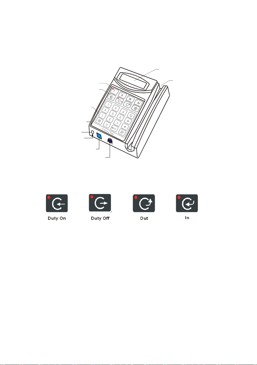
6. The ability of shift-management provides 4 shifts, out and return keys.
7. The real-time (on line) function allows the computer to monitor 20,000
persons. And save into the hard disk in synchronous.
8. Auto detect serial port and auto-configuration system settings -- the
progress of computer technology that bring much convience, but the
hardware and peripheral devices are getting more complicated. The
TR3800 provides a auto-searching function to dectect computer’s serial
ports and save to setting value.
9. Offers flexible record format that suit the output pattern to diversity of
personnel management application systems.
10.An external alarm system provides 112 alarms (16 alarms for each day
a week) , the definable duration from 1 to 99 second(s).
11.Embeds 2,000 perssons security and 3-grade access control.
12.Supports full function TCP/IP LAN links – Local LAN, WAN, IntraNet
and InterNet

6
1.2 Hardware Specifications
Housing ABS+PC+SyntheticFiber
Display STN back-light LCD (16x2 characters)
Keypad 24-key membrane keypad (water-resistant)
Memory 128K-2M ultra-speed RAM
Calendar 1950 ~ 2999
Clock +- 15 seconds/per month
Battery Ni-Mh 4.8V Recharageable/2100mA
Li 3V CR2032H /220mA
Card Reader EM 125K/Wiegand RF 10-digit and 8-digit
Mifare13.56Mhz(optional)
Bar code sloter/code 39
Magstripe sloter/ISO Trk1,2,3 (200oe,,4000oe)
External Alarm 1-99 second(s) , 3A/250V AC
Access Controller 1-99 second(s) , 3A/250V AC
Comm. Model TCP/IP – LAN, WAN
RS232
Multi-Drops(RS485)
Modem (V.32, V.34, V34+, V90)
BluetoothWireless(optional)
Comm. Speed 10M,100M,1000M
Cable 232-30 (for RS232)
MDP-30 (for RS485 multi-drops)
MOD-30(forModem)
Power Consumption Normal mode 9-12V/350mA --3.15W
UPS mode 4.8V/320mA --1.54W

7
Temperature Operation: -10 ~ 50 degrees Celsius
Storage : -40 ~ 70 degrees Celsius
Humidity Operation: 10 ~ 95 %
Storage : 5 ~ 95 %
Sea Level -304.8 ~ 3657.6 meter
Dimension 114mm(X) x 165mm(Y) x 44mm(Z)
Weight Net : 0.5Kg
Gross : 1.0Kg (accessories and package included)

1.3 Appearance Illustration And Status Keys
Appearance Illustration
LCDDisplay
Card Reader
Keylock
Multi-communication Port
Power Socket
Membrane Keypads
Shift Keys
Status Keys
Alarm/Security/Printer
Outlet
Ground Connection
Outlet
Status Keys
8

9
Chapter 2 Hardware Installation
The package of TR3800 includes the following units, please check them
before installation.
1. TR3800 Time-Recorder
2. Two Keys
3. Power Adaptor (100-240V AC / 9-12V 1200mA DC)
4. TR3800 CD (for Communication Wizard software and user’s manual)
5. 232-30 Cable
6. MDP-30 Cable
7. MOD-30 Cable
The package of model TR3800xN(TCP/IP embedded) don’t include above
3 cables (item 5,6,7)

10
2.1 Hardware Requirements
The TR3800 is designed for using with PC/AT ( Pentium4, Core2Due*
or above processor) and other compatible computers under Microsoft
Windows* ( 10 / 8 / 7, Server 2008/2003, XP, 2000, NT ) 32-bit & 64-bit
system. Besides the TR3800 Time-Recorder, be sure that you have the
necessary equipments as follows:
TCP/IP LAN Link – TCP/IP Single or mult units(TR3800xN)
A 10/100M/1000M Lan device with RJ45 connector in the computer
RS232 – for Single Unit
1. A serial port (Com1 ~ Com10) in the computer
2. A 232-30 cable --- can be extended to 15M by standard DB9P cable(one
end with male connector, the other end with femal connector)
Multi-drops – for Multi Units or Single Unit (above 15M)
1. A serial port(Com1~Com10) in the computer
2. An A52(232-485ADDC) signal converter (optional)
3. A MDP-30 cable --- can be extended up to 1,200M via 24AWG cable
Modem Link – for Single Unit
1. A serial port(Com1~Com10) in the computer
2. Two sets of Modem(one for computer, the other for TR3800)
3. A MOD-30 cable
* Pentium and Core2Due are registered by Intel Corporation
* Windows 10 / 8 / 7, Vista, XP, NT are registered by Microsoft Corporation

2.2 How To Read The ID Card
Reading Proximity Card
1. Take the card approach to the right hand of machine ( 8-15cm)
2. A sound of beep and ID number showed on display
Reading Bar Code Card/ Magstripe Card
1. Keep the bar code toward the keypad( the other side for
magstripe card)
2. Slide the card from top to bottom smoothly
3. A sound of beep and ID number showed on display
11

2.3 How To Settle The Machine
Sit on the Counter
1. Unplug the power cord
2. Outspread the stands
12

Mount on the Wall
1. Unplug the power cord
2. Press and turn the key in right-hand (unlock) to separate the cover from
bottom
3. Mount the bottom on the wall
4. Unite the cover with bottom
5. Turn the key in left-hand (lock it. If not turn to the correct angel, the key
cannot be removed)
6. Remove the key
13

2.4 Internal Connectors of TR3800
Opening the TR3800, it appears various kinds of connectors, all of these
connectors are designed under anti-fool notion and all connectors marked the
function with text description as well. All mistaken connections will not cause
hardware damage, but it might cause communication failed.
JP8
- 9V +
VR1
JP5
T1 : External Alarm Terminal
T2 : Access Controller Terminal
: LCD Contrast AdjusterVR1
S1 : UPS Switch
JP8 : 2nd DC Power Connector
JP10 : 2nd Multi-drops Connector
JP9 : 2nd RS232 Connector
ON
1
UPS
BAT
JP9 TX
RX
G
JP10
D-
D+
T1
A
LARM
SEC
T2
D23D34
D34
D23 : Power LED
JP7 : 2nd LAN Pin
ETX+
ERX-
ETX-
ERX+
JP7
S2 : LAN Reset
S2
LAN
RST
* Items of D34,JP7 and S2 are workable for model TR3800xN only
* Press & Hold S2 + Power-on+ Release S2 to reset the Lan device
14

2.5 How To Set Machine ID
When many machines link on the line together that need to set the
machine’s ID for unique identity (“001” is factory setting). Any machine’s ID
can not be equal to any of others , otherwise link-error!
1. Press & hold Exit-key and than Power-on
2. Input Password “3198” – date and clock blinking
3. Press Combined Func-key
4. Input “210”
15
5. Use forward or backward to change machine ID
6. Press toconfirmand toexit

2.6 Link Modes
TCP/IP LAN Link (Model TR3800xN TCP/IP Embedded)
HUB
16

RS232 (Model TR3800x maximum distance 15M)
PC RS232
232-30 CABLE
Multi-drops RS485 ADDC (Model TR3800x maximum up to 1,200M)
Transio
A52
12
RS-232
TR0 1
TR0 2
DC
Adaptor
PC RS232
MDP-30 CABLE
Maximum 1200M(6,000 feet)
Red
Black : D+
: D-
17

Modem Link (Model TR3800x)
MOD-30 CABLE
MODEM MODEM
PC RS232
** The Modem of TR3800 side must be Initiated by InitiateMODEM.exe
18

2.7 LCD Display And External Alarm/Access Controller
LCD Display:
When the TR3800 work normally, the LCD display shows date/week on the
first row, the second row for time and space(free space) information.
2018-05-15 TUE
10:30:25 95KB
While reading the ID card, the display shows the ID number, time and
storaged records for 20 seconds.
0213257898
10:30:25 1612
External Alarm and Access Controller:
The external alarm and access controller terminal are located on the
right-side of mainboard. The relative information, please refer to 2.4, 6.2,
6.1.4 and 6.4.
Alarm/Security
Trigger
1.ControlTrigge
r
Power
Alarm/Security
Power
2.ControlPower
Circuit
Load
Max. 2A
19
Other manuals for TR3800
1
Table of contents