Argiriadis Analogue Electronics DU EQ 2022 User manual

DU EQ 2022
DU EQ 2022 USER GUIDE
STEREO

Page 1 of 25
Contents
Contents .......................................................................................................................................................... 1
PLACEMENT .................................................................................................................................................... 4
THE MAIN UNIT ........................................................................................................................................... 4
THE POWER SUPPLY UNIT ........................................................................................................................... 5
GROUND LIFT SWITCH ................................................................................................................................ 5
PRECAUTIONS ............................................................................................................................................. 6
OPERATING GUIDELINES CONTROLS & SWITCHES ......................................................................................... 7
(1) INPUT SECTION ...................................................................................................................................... 7
(2) PASSIVE EQ SECTION ............................................................................................................................. 8
(3) ACTIVE EQ SECTION ............................................................................................................................... 9
(6) MAIN DIFFERENCES BETWEEN SE & PP STAGES ..................................................................................10
BIAS CONTROL AND HOW IT AFFECTS DISTORTION AND CLIPPING IN THE SE DISTORTION SECTION.....12
(7) SINGLE ENDED DISTORTION SECTION .................................................................................................12
DIFFERENCES BETWEEN TRIODE & PENTODE ...........................................................................................13
(8) THE PUSH PULL (PP) OUTPUT STAGE...................................................................................................14
PREPARATION BEFORE SWITCHING ON/TESTING ........................................................................................16
switching on/testing .....................................................................................................................................18
(14) The Single Ended Distortion Stage (SE) .............................................................................................21
ABBREVIATIONS ........................................................................................................................................24

Page 2 of 25

Page 3 of 25

Page 4 of 25
PLACEMENT
THE MAIN UNIT
The location of the distortion unit (DU) is important.
Its location/mounting must allow adequate air circulation from below, the sides and above it to disperse
the heat that the tubes/semiconductors generate.
Avoid hot locations such as near radiators or other heating units.
IF THE UNIT IS MOUNTED ON A RACK:
(a) If mounted on a rack ensure that the unit below it does not get hot.
(b) Even if the unit below the DU runs cool, there must still be a distance of at least a 2U (3(1/2) inches,
90mm) of empty air space between the DU and the unit below. If the unit below gets warm this gap must
be increased by least 4U (7 inches,180mm).
(c) Leave a 4U distance of empty air space between the DU and the unit that is on top of
it.
(d) both sides of the whole rack must be open to allow air passage.
(e) Also, if the unit is mounted on a rack it may need extra support from below due to its weight. A
sturdy rack shelf is suitable the 1" feet will allow air to enter from below.
Keep the top clear of items such as papers or anything that could block air passage and
cause overheating.
PLACE THE UNIT AWAY FROM SOURCES OF INTERFERENCE
(a) AC power lines, fluorescent lights, fans etc.
(b) The power supply cords that are plugged to the power supply must always run from behind the unit
never along its sides to the power supply.
(c) If the room where the unit is operated is electrically and/or magnetically noisy, you may have
to slightly move it around and find the most suitable location in order to completely eliminate any noise.

Page 5 of 25
THE POWER SUPPLY UNIT
(a) Before you connect the power supply to the mains, connect the two power supply cords to the
power supply sockets. These are the two cables, one grey and one black, that come out from the back of
the main unit. Please treat both cords with care.
Both of the plug connectors at the end of these cables and their respective sockets on the power supply
front panel are mated in only one possible orientation. The smaller round high voltage plug at the end
of the black cord features keyway polarisation: it has a notch to make possible to fit in one way only.
The bigger plug on the grey cord and its socket (on the power supply) are also non-reversible, they
have a flat side in the middle to make them mate one way only.
Please examine both sockets and plugs before connecting to recognise their mating features and do not
use any force when inserting the plugs into their sockets.
(b) The power supply is also a source of electrostatic and magnetic interference and it must be placed as
far away from the main unit as possible, preferably on the floor.
(c) Please allow plenty of ventilation for the power supply unit too. Avoid hot locations such as
near radiators, heating units, hot central heating pipes etc.
GROUND LIFT SWITCH
If this switch is used incorrectly the unit will become susceptible to interference, noise and hum.
Ensure that this switch which is situated in the rear panel is in the on position which is with the (I) pressed
down. This is to ensure that the metal case is connected to the negative signal ground of the unit's
electronic circuits so that it (the metal case) works as a shield against external interference but also
prevents internal instability and oscillation.
In most studios and especially if the balanced (XLR) inputs and outputs are used it may never be
necessary to operate this ground switch, so there is a piece of tape to keep it in the ON position at all
times.
If you need to operate this switch (see notes on ground lifting & loops) just pull the tape off.
It is important to remember that unless the case is shielded (connected to the signal ground) by other
means if the GROUND LIFT SWITCH in is the off position the unit will be noisy.

Page 6 of 25
PRECAUTIONS
Please do not leave the unit switched on when not in use
Each time:
(a) you increase any gain settings
(b) change from triode to pentode,
(c) operate in OFF LOAD mode
(d) operate in positive feedback (PFB) mode
Ensure that you decrease the OUTPUT P14 control and/or use the attenuator (OUTPUT
ATT) switch (SW21, in the right position) so that the output level of the unit remains as constant
as possible.
Until you get to know the unit, always turn the OUTPUT control (P14) down to zero whenever
you change anything and then gradually turn it up again.
Ensure that output overload LED OD3 is always off.
Always set the S-BY/ON switch on S-BY (up) before you use the TRI/PE1/PE2 (P15) rotary
selector switch and then press S-BY/ON down again (ON). This procedure is explained in the
'THE OPERATING GUIDELINES' section.

Page 7 of 25
OPERATING GUIDELINES
CONTROLS & SWITCHES
DUAL MONO
(a) The Tube amplifiers in this unit do not employ any form of negative feedback (NFB) in order to retain
the harmonic sonic character of each tube and to be able to overdrive it to its full extent softly or harshly
depending on how the controls/switches are set.
NFB not only reduces distortion but it also offers accurate amplification by controlling parameter
tolerances of each tube. The gain (and other parameters) can vary from tube to tube (of the same type).
Components like the potentiometer controls, signal capacitors, etc have small tolerances too.
For these reasons individual minor fine adjustments of each channel may be necessary in order to make
them produce exactly the same output in some operating modes. For instance, sometimes, a
drive/level/output control in one channel may need to be set at 5(1/3) (= a third of the distance between
5 and 6 on the knob dial) while the same control is set at 5 in the other channel.
(b) Due to the complexity of the unit I personally found it easier (when operating for the first time) to
fully test one channel first, then the other and finally align them both in stereo mode.
(c) When I switch on each unit for the first time, I also prefer testing each section separately (in each
channel) and then mix them altogether. For instance, test the whole channel without the SE (single
ended) and active EQ sections then bring in the SE section, then the active EQs and so on. It is possible to
test each section separately.
(1) INPUT SECTION
P1: INPUT LEVEL CONTROL, it adjusts the amount of signal level that enters the unit from the unbalanced
(jack) input
SW1: INPUT STAGE SELECT SWITCH
This switch selects the operating mode of this stage. In the up position is triode (TRI) in
the down position cascode (CASC) mode
In triode mode, at low P1 settings, the input stage will produce a clean sound, but with 'musical' low order
even (mainly second) harmonic distortion, the amount being directly proportional to the signal level set by
P1. The more you turn up P1, the more harmonic and intermodulation distortion is generated, resulting in
noticeable sound colouration.
Cascode mode, is to be used for harsher and dirtier sound. Cascode is a low noise pentode made out of
two triodes (= CasCaded triode), that produces more distortion even at lower P1 settings. The distorted

Page 8 of 25
signal contains both even and odd products. Bass, drum-loops and keyboards/synths sound interesting in
this mode. However, it also amplifies more.
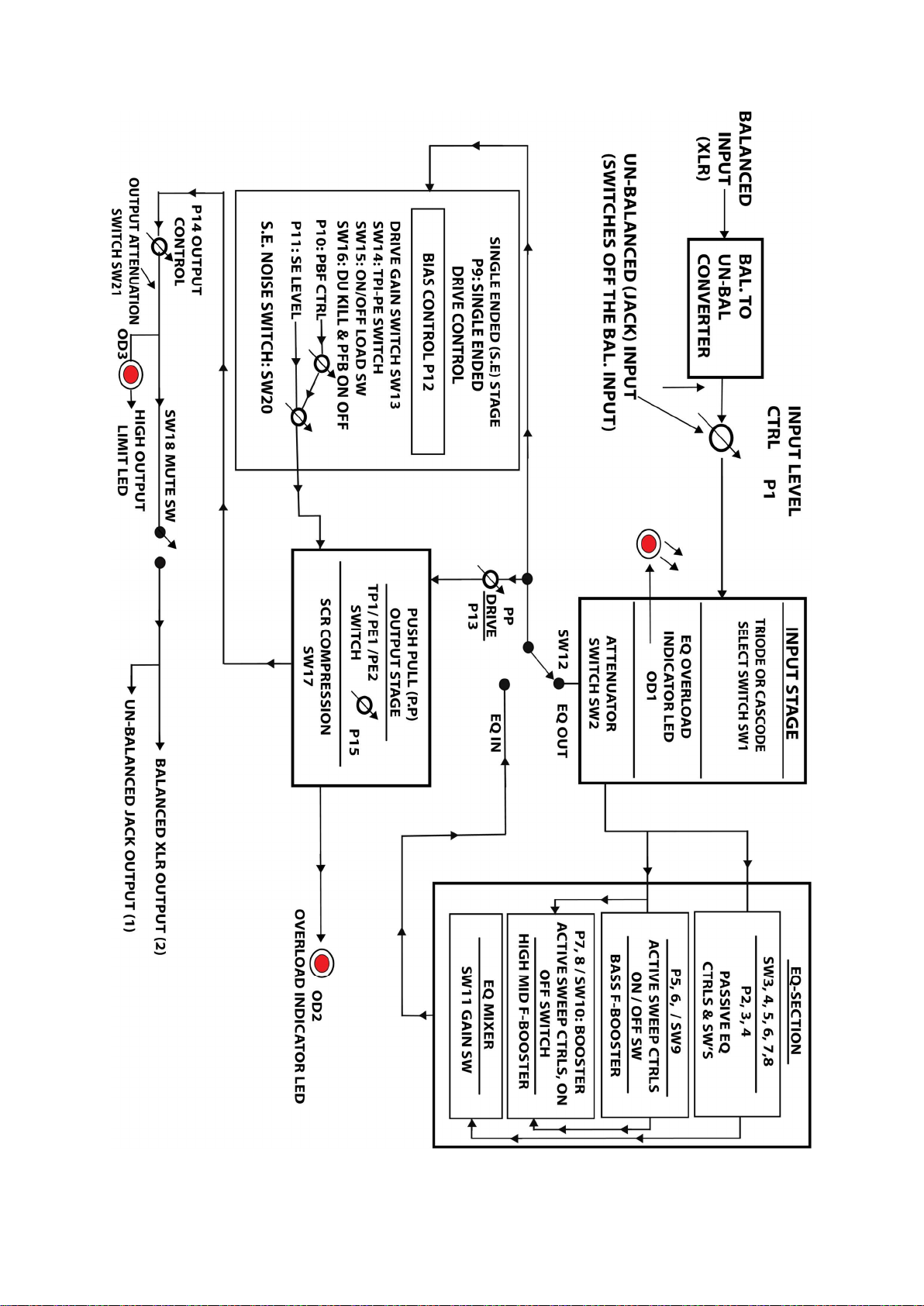
The SW1 (TRI/CASC) converts the input stage (as already explained) from a Triode to a cascode circuit
with more distortion and gain.
During the change the operating conditions of the two input tubes change rapidly and the signal
may disappear for a very short period of time.
(a) in order to avoid premature failure of either or both of these tubes please disconnect the high
voltage (B, HT) through setting the S-BY switch in the up position before operating SW1 and re-connect
the high voltage afterwards by pressing the S-By down again.
(b) The changeover is a noisy procedure so the MUTE (SW18) switch can be pressed while operating SW1
(and the HT switch) to silence the output of the unit.
Procedure (a)&(b) above is the same as the one used for changing from Pentode to triode (and vice
versa) in PP output section. This procedure is discussed in detail further in the text. (see PRECAUTIONS,
OPERATING GUIDELINES, and SWITCHING ON/TESTING.
SW2: ATT, an attenuation switch that reduces the signal level coming out of the input stage by 12dB's.
This is to avoid overloading of the following stages, when the input stage (especially in cascode mode),
produces a high-level signal, when (and if) this type of overloading is not wanted.
(2) PASSIVE EQ SECTION
This is a passive EQ, with an inductor in the midrange section, that can emphasize certain harmonics,
eliminate others and add a certain character to the sound.
P2: BASS, a shelving type control for the low frequencies.
SW3: L /H, bass frequencies select switch, when P2 starts having a noticeable effect
L = 70Hz, H=100Hz
SW4: ON, bass on /off switch, it is not a 'kill' switch, but it cuts off the low frequencies.
P3: MID, midrange frequency control.
SW5: L/H, midrange frequencies select switch, see text below
SW6: ON, mid control (P3) on /off switch
P4: TREBLE, a shelving type control for the high frequencies.
SW7: L/CENTRE/H, treble frequencies select switch when P4 starts having a noticeable effect
L= 4.5kHz, centre =9kHz, H = 7kHz
SW8: ON, treble on/off switch it is not a 'kill' switch, but it cuts off the high frequencies.
This EQ interacts both with the stages before it and the stages after it. For instance, you can:

Page 9 of 25
a) overdrive the input stage, before the EQ and use its controls to either boost or filter out harmonics that
have been generated by the input stage, especially in cascode mode.
Another option may be to:
b) keep the input stage clean, (Triode Low distortion mode) and cut or boost certain frequencies of the
signal that enters the following stages (SE & PP DU's) and overdrive these stages.
c) Most commonly used option is a combination of a) and b).
The Bass and Treble is a Baxandall tone control, switch SW3 selects the low frequencies below which
maximum variation occurs, switch SW7 selects the high frequencies above which maximum variation
occurs. When SW7 is in the centre position the frequencies controlled by P5 are too high (often called “air”
frequencies) and the variation is not very audible.
When SW3 is set in H and SW7 in L, P2 and P4 become more responsive and interactive.
When SW5 is set in L control P3 affects a wide range of low mid- frequencies centred at 500Hz and the
sound becomes fuller on high P3 settings. When SW5 is set in H, P3 affects a narrower range of higher
midrange frequencies centred around 1kHz.
By turning P3 fully anticlockwise, or by switching off the mid switch SW6 most of the midrange
frequencies disappear and the Bass & Treble (P2, P4) controls become more effective.
(3) ACTIVE EQ SECTION
(a) BASS Variable Frequency Booster (VFB)
This is an active Variable Frequency Booster (VFB), a high Q ( + 27dB) band -pass filter at a frequency set
by SWEEP control P6. It uses both Negative and Positive Feedback mechanisms to function and swings
between the two. This circuit works in a way as if it is “trying” to oscillate at the chosen frequency but
never actually gets there. P6 selects this frequency from 30Hz to 350Hz, and the BOOST control P5 sets
the output level entering the EQ mixing stage.
This is a hybrid circuit, made out of a 12AX7 tube voltage amplifier and a high voltage transistor buffer.
The 12AX7 is producing a small amount of harmonic distortion and its unique grid current behaviour set
by the operating conditions of the circuit plays a role in the sound.
P5: BASS BOOST control
P6: FREQ, bass frequency SWEEP control
SW9: ON bass frequency booster on/off switch, when pressed down the boosted signal enters the EQ
mixing stage; it can also be used as a KILL switch.
(b) HIGH MID Variable Frequency Booster (VFB)
Same as the previous circuit but its frequency range (900Hz ... 4.2kHz) covers the high midrange and
presence frequencies.
P7: FREQ, high mid frequency SWEEP control.

Page 10 of 25
P8: HIGH MID BOOST control
SW10: ON high mid frequency booster on/off or “KILL” switch
There is a limiter before the input of both bass and high mid VFB's to avoid overloading them. Such type
of overload must be avoided because it will result into instability and hard clipping.
On high level signals, after a certain amplitude has been reached, this limiting action creates a form of
compression and adds some sustain in the narrow range of the chosen frequencies. It also generates
distortion in the frequencies that the booster circuits reject but are near their narrow bandwidth.
OD1: this LED is lit when the signal that enters the VFBs has reached a level high enough to activate the
limiter.
NOTES ON EQ SECTION (ACTIVE & PASSIVE)
(a) The output of the ACTIVE EQ section can produce a much higher signal level output with
far more distortion than the PASSIVE section which only slightly colours the sound.
The high-level signals from the active section are in the low and high mid frequencies and BASS BOOST &
HIGH MID BOOST controls (P5&P8) are logarithmic to enable fine adjustment at settings below 5.
These controls can be set low (at first at least until you get used to the unit) especially if the EQ
gain switch (SW11) is set in the high (H) position. You can set this switch for higher EQ gain if you need
more signal coming out of the Passive EQ section.
(b) The ACTIVE section also produces more distortion in the frequencies that the two Variable Frequency
Boosters (VFBs, or resonators) do not affect as already mentioned in the text.
(c) Because of the nature of the VFB circuits (positive& negative feedback, oscillating effect, distortion
etc) and tube tolerances the signal boost is not 100% equal at all sweep frequencies and amplitudes vary
slightly from channel to channel so some fine re-adjustment may be necessary through the P5,
P8 boost controls every time the sweep P6/P7 controls are used.
(4) The signals from the passive and active EQ stages enter the EQ MIXING stage where:
SW11: L/H a gain switch; the EQ MIXING stage provides a +9.5dB of gain when this switch set on H.
SW12: EQ IN/ OUT switch, it bypasses the whole EQ system when set in OUT.
(5) After SW12 the signal splits in two parts:
(a) it enters (PP) Push Pull output stage through the P13: PP DRIVE control, that adjusts the amount of
signal level entering the Push Pull output amplifier.
and
(b) it also enters the Single Ended (SE) distortion stage.
There is a mixing stage inside the PP stage that mixes the output of the EQ MIXER and the output of the
SE DU stage.
(6) MAIN DIFFERENCES BETWEEN SE & PP STAGES

Page 11 of 25
Both SE and PP stages can function as clean audio amps with very little distortion only high enough to add
colouration and “warmth”, if they are driven softly by adjusting their corresponding level controls and
mode switches. They are both working in 'open loop' mode i.e. there is no Negative Feed Back (NFB)
applied to them.
But there are two fundamental differences between them:
(a) The SE stage, in Triode (TRI) mode, is producing mainly even harmonic distortion, and in Pentode
(PE) mode a combination of even and odd.
The PP stage in itself does not produce even harmonic distortion, just odd.
The order and the amount of the distortion in both stages increase the harder they are driven.
(b) The SE creates a lot more “crunchy” type of distortion in the low frequencies especially in Pentode
mode when it is driven a bit harder. This is due to the fact that the choke that forms part of the output
load is gapped to avoid core saturation, so its inductive reactance is lower and thus loads the output tube
in the low frequencies.
The PP on the other hand has a full smooth bass sound with more headroom and it does not distort the
bass as quickly as the SE does, but it produces a different, type of bass distortion heavier and “warmer”.
(c) The SE can sound bright and sharp on the treble especially in PE mode, even more
in PE and NO LOAD mode.
There is a big difference in low frequency sound signals between the SE and PP
stages especially when they are overdriven.
(d) In some settings the signals level dynamic range can be higher in the SE than in the PP stage so it
would sometimes appear that the SE stage produces far too much gain. This is for two reasons:
The SE stage must be able to produce anything from a clean smooth sound to very extreme and
much higher distortion levels than the PP stage does. For this reason, it must be capable to
generate ample amounts of gain if set so; for instance, it has an extra gain SE-GAIN (SW13) plus
OFF LOAD and PFB (Positive Feed Back) modes.
The SE stage drives the PP stage, so any SE gain increase will also appear in the PP stage which is
also the output stage.
SE LEVEL P11 control is a logarithmic type to enable fine adjustment at levels below 5 (on the P11 dial)
(e) The latest version of the PP stage has been designed so that (only when over-driven) one half of the
(signal) cycle grid-clips softly earlier (than the other half) so that results in a relatively small amount
of even as well as the odd harmonic distortion.
This slight half cycle soft grid clipping occurs in Triode mode (TRI) and to a lesser degree in
Pentode (PE2) mode.

Page 12 of 25
BIAS CONTROL AND HOW IT AFFECTS DISTORTION AND CLIPPING IN THE SE
DISTORTION SECTION
The output stage of the SE section has a bias control that sets the amount of DC current that flows
through the output tube and output inductor under idle (no signal) conditions.
The lower this bias control is set the higher the even harmonic distortion generated by the SE output
stage will be.
When the power (output) stage is driven hard:
(1) One part (say for instance the top half) of the waveform clips because the output signal in the power
tube is entering its cut off region and this is called cut off clipping.
* Cut off clipping is soft and builds up gradually.
(2) The other part (say for instance the bottom half) of the waveform clips because of:
(a) In triode mode
An electrode at the input of this tube called the grid starts drawing current and this is called grid clipping.
*Grid clipping in most control settings starts abruptly and is hard and makes bass sound “crunchy".
The higher the bias control is set the higher the grid current effect is.
(b) In pentode mode
(i) the same grid current effect takes place that occurs in triode mode
(ii) the output signal in the power tube is entering its saturation
region
*In most control settings in pentode mode saturation clipping is gradual and it coincides with grid
clipping. As a result, this creates a softer clipping in this part of the cycle despite the harshness of the grid
current effect unless the tube operates in high bias currents where grid clipping takes place before
saturation.
*At certain settings in both triode and pentode mode you can create a symmetrical output waveform
where both parts of the signal 's cycle clip softly
(7) SINGLE ENDED DISTORTION SECTION
P9: SE DRIVE control, it adjusts the signal level that enters the output tube of this stage. On low settings,
and in triode mode, the sound will be clean, with a small amount of second harmonic distortion,
introducing mild colouration. On higher P9 settings, the distortion increases especially in Pentode mode
at a rate proportional to the signal strength. At the same time the SE output signal will increase too.
P11: SE LEVEL control, it adjusts the level of the SE output signal. P11 may have to be turned down if it is
necessary to keep the same signal level coming out of the output of the SE DU as P9 is turned higher, in
order to achieve more distortion.

Page 13 of 25
P12: BIAS control it sets the amount of current that the SE output tube is operating on.
SW13: SE-GAIN, L/H when this switch is set in H the gain inside the single ended stage is increased by
11.6 dBs.
SW14: TRI /PE switch, it selects Triode or Pentode mode of operation for the SE DU output tube.
DIFFERENCES BETWEEN TRIODE & PENTODE
At low input signals triodes produce predominantly second harmonic distortion which is more musical. SE
DRIVE control P9 can be set low to drive the DU softly if this kind of sound colouration is desired and to
avoid clipping .The amount of distortion is directly proportional to the signal amplitude set by P9 and that
means as this control is turned up, more distortion will be generated (especially if the SW13 switch is set
in H), first low even, then low odd (like third ) and a smaller amount of higher orders both even and odd,
until eventually soft clipping occurs.
In PENTODE mode the distortion starts earlier as far as P9 is concerned. Pentode output will produce more
third and higher order odd distortion products in addition to second and higher even products by
overdriving it when increasing the signal drive through P9 (and/or setting SW13 in H), resulting in a harsh
and edgy sound and a boost in high mid and treble.
SW15: ON/OFF LOAD switch, it disconnects the internal load that the SE DU is connected to. It is more of
an effect when SW14 is set in PE mode, and under these conditions extreme distortion, echo-y sound (in
some frequencies) and shrill treble is the result.
It is highly recommended to turn the output level control P14 all the way down to a very low setting,
until you get used to the high-volume level of this particular effect. This is because the output signal can
reach very high levels when the SE output tube operates in the Pentode OFF LOAD mode. SE DRIVE
control P9 must also be set low when you experiment in OFF LOAD for the first time.
SW16: KILL & PFB this is a switch, that serves three purposes:
(a) When pressed down it kills the output of the SE DU
(b) In the centre position the SE DU is on, and it enters the PP output stage.
(c) In the up position (labelled PFB) it enables the output signal to re-enter the input of the SE DU in
such a manner as to increase its strength and generate the Positive Feed Back (PFB) effect.
P10: PFB control, it adjusts the amount of the signal re-entering the SE amp. It must be used carefully, if it
is turned high enough the SE DU will start oscillating. The trick is to turn it up until oscillation starts, then
back off a bit until it stops. Again, when you operate in Pentode , and especially in PE /OFF LOAD mode
the PFB effect becomes more extreme.
SW20: noise gate switch, it only affects the single ended section (SE DU).
If you operate the SE DU on a high gain mode for high distortion, like OFF LOAD, PENTODE, with the EQ-
GAIN&SE-GAIN SW11&SW13 switches set in high gain (H) and especially with the HIGH MID BOOST P8
control set high you can press this switch down to remove hiss and noise.

Page 14 of 25
For low SE DU distortion (just mild colouration) and low P8 settings, you can keep this switch in the up
position because it introduces crossover distortion, unless of course you want to add this type of
distortion to the mix.
(8) THE PUSH PULL (PP) OUTPUT STAGE
P13: PP DRIVE control it adjusts the signal coming out of the EQ mixing stage and entering the PP stage if
the EQ IN/OUT SW12 switch is set in 'IN'.
If SW12 is set in 'OUT' the PP drive control P13 picks up the signal directly from the output of the INPUT
STAGE.
The SE DU stage also feeds the PP stage, and SE LEVEL control P11 adjusts the SE signal entering the PP
stage.
The output of the Equalizer (EQ) also drives the SE stage if SW12 is set in “IN” and there is a summing
network at the input of the PP stage that mixes these two signals.
The PP stage is the output stage of the whole unit and it free of global NFB.
Global Negative Feed-Back is a distortion correction network. It samples the output signal of a circuit and
feeds an out of phase portion of it to its input and by doing so it removes distortion.
This output stage can operate as a linear amplifier by
(a) Setting P11 and P13 low
and
(b) Operating in Triode mode. Just like in the SE stage , distortion in the PP stage is also proportional to its
input signal amplitude and it will first occur in the low frequencies (Bass) due to saturation in the output
transformer. The PP output transformer primary inductance is quite high, so in triode mode it has little
effect on the distortion.
OD2: PP stage overload LED.
This will light up when this stage starts distorting on the Bass. Controls P11 and P13 can be turned
down as soon as OD2 lights up, if it is desired to keep the PP stage in clean mode. The PP stage is
designed to clip very softly.
P14: OUTPUT level control, it sets the output signal level of the whole system. As in the case with the
single ended DU, if the output becomes low because P11 and P13 are set low to achieve a clean output,
P14 must be turned up to get the right volume. With P14 all the way up, the maximum undistorted
output in PP triode mode at 30...40Hz is 5.3V RMS (= + 16.7 dBu) approx.
Obviously, if the PP stage is set for distortion by turning P11 and P13 up, P14 must be turned down in
order to maintain the same amount of volume. P15:TRI/PE1/PE2 rotary switch, it selects between
TRIODE and two different modes of PENTODE operation. Always set the S-BY/ON switch on S-BY (up)
before you use the P15 rotary switch and then press S-BY/ON down again (ON). This procedure is
explained in the 'THE OPERATING GUIDELINES' section.

Page 15 of 25
Triode operation is preferred for clean sound like in the SE DU , whilst Pentone (PE 1) gives more
distortion by operating the Screens of the output tubes at a lower voltage. Pentode operation in PE 2 is
cleaner, with more headroom due to the higher Screen voltage.
SW17: SCREEN COMPRESSION switch, this effect introduces a mild compression by limiting the screen
current and it is more noticeable in PE 2.
OD3: output limit LED indicator, it will light up when the output signal reaches 8.2V RMS (= +20.5
dBu) sine wave approximately.
The OD3 led will light up at a lower output level around +19dBs similar to the older units. After the OD3 is
lit the output can still reach a maximum 25V peak to peak square wave.
When that occurs, the in-built limiter will ensure that the output signal never exceeds that signal level by
making it clip very hard. To avoid this happening the output level control P14 must be turned down as
soon as OD3 starts lighting up, in order to avoid hard clipping and overloading the equipment that the
unit is driving. Therefore, to keep the output signal at reasonable levels OD3 must never light up.
The OD3 indicator must not be confused with the OD2 which indicates (as already mentioned) the
PP output stage overload condition on the bass. The output control P14 has does not affect the OD2 led
because P14 is placed after OD2. It is safe to overload the PP DU and let OD2 light up, but you must make
sure the output is kept low through P14 and OD3 must never lights up.
The restriction in the amplitude of the output signal is achieved by a clipping circuit and this clipping
is hard and sounds very harsh.
HT SWITCH or STAND- BY SWITCH (S-BY), it applies the high voltage (SW19) on the tubes when pressed
down.
SW21 This is the output attenuation switch which when pressed to the right, it introduces a -6bB
attenuation in the output signal.

Page 16 of 25
PREPARATION BEFORE
SWITCHING ON/TESTING
Connect the main unit to the power supply unit.
(1) Ensure that the stand-by switch on the front panel of the of the main unit is OFF, i.e. the up position.
This is because the high voltage (HT) must not be applied to the tubes until they warm up.
FOR THE FIRST TEST
(2) Turn these level controls fully anticlockwise: INPUT P1, BASS BOOST P5 , HIGH MID BOOST P8 , SE
DRIVE P9, SE PFB P10, SE LEVEL P11 , PP DRIVE P13 and OUTPUT P14
Once you are familiar with the unit you may only have to turn P14 down to zero before switching on.
IMPORTANT NOTE
This unit can produce a large amount of gain and high output levels, but its output is internally limited
by restricting the amplitude of the output signal (through hard clipping) as soon as it reaches 8.2V RMS
(20.5dBu). However, even with this protection, if you accidentally send a high signal through it (for
instance a loud buzzing noise caused by a faulty input lead ) it may generate enough of an output to
damage your monitor amp or speakers on certain settings if the OUTPUT control P14 is set
unreasonably high.
Also, P14 must always be turned down when you operate in Pentode OFF LOAD and/or the
positive feedback mode (PFB, P10), because the output may become too high.
The Bass sections (Bass control P2, Bass sweep boost P5) and the high mid sweep (boost P8) section can
produce high outputs too.
It is therefore advisable to start quietly and then gradually turn the levels up so that you can keep
control of the units overall output level.
Due to the complexity of the system for the first test, start with the Input Stage, passive EQ and output
PP amplifier only, and then try one of the other sections at a time.
(3) Ensure that the input stage ATTENUATION switch SW2 is OFF, i.e. in the up position.
(4) Set EQ gain switch SW11 on low gain i.e., in the left position.
(5) “Kill” Bass and High Mid F-Boosters, by turning SW9 and SW10 up
(6) “Kill” the SE DU stage by pressing PFB/KILL SW16 switch down.
(7) Set passive Bass/Mid/Treble EQ frequency select switches SW3 on H, SW5 on L and SW7 on L.

Page 17 of 25
(8) Set EQ OUT /IN switch SW12 on IN.
(9) For a flat response set Bass control P2 on half, Mid P3 just over half and Treble control P4 just below
half.
(10) Press tone control switches SW4/SW6/SW8 down i.e. ON.
(11) Set TRI/CASC (triode/cascode) select switch SW1 on TRI (Triode).
(12) Set PP output stage mode rotary select switch P15 on TRI (Triode) mode.
(13) Until you get used to the output levels of the unit set the OUTPUT ATT switch SW21 in the down
position, to introduce output attenuation.
(14) Connect the output of the unit to a sound monitor, with an INPUT IMPEDANCE of at least 10K.
When the output is taken out of the un-balanced JACK, one side of the balanced output XLR is
grounded, if the jack plug used is a mono type, they are the ones with no ring, just sleeve and tip.
These are the only jack plugs to be used for both inputs and outputs of this unit. Please do not use both
balanced and unbalanced outputs simultaneously.
(15) Connect a sound source of an average level of 0dBu (0.775V rms) into the input of the unit (*)
This figure refers to the jack unbalanced inputs and it is an approximate value. For the XLR balanced
input I would increase that to 0.753dBu (0.845Vrms), a very small increase since the input balanced to
unbalanced transformer introduces a 0.753dB attenuation.
All my units use this input signal level for the various control knob number references I mention
throughout the manual. Under these conditions (*) you will have to set P1 in approx. 5 for led OD1 to
light up.
For higher input level sources like +4dBu or more you will have to set the INPUT CONTROL P1 to a lower
setting.
The input level control P1 works well for even higher inputs; for instance, at a +10dBu input signal you
may have to set P1 to around 2 for OD1 to just about light up. This is because P1 is a logarithmic control.
However, in settings below 1 it may be difficult to fine tune the two channels.
Another important thing to emphasize here is that you can overdrive the input anyway in which case
those settings I mention above can be ignored. The settings and the recommended input levels are only
given for the specific case of generating a clean, very slightly coloured output signal in the low
frequencies (around 30Hz) when the input stage is operating in triode mode and the output stages (SE
and/or PP) are also in triode mode. This is a good way to start and then move into more distortion
gradually.
In tube circuits with no distortion control networks like overall NFB (negative feedback), input levels are
integral to the way in which these circuits create a 'tone'. The design of the input section must also
provide a lot of gain and distortion if a 'dirty' sound is required. It is part of a distortion unit after all and
that is what it does at high P1 settings especially in cascode mode, hence the restrictions in input levels.
If you use the unbalanced (JACK) input the balanced (XLR) input is automatically disconnected.
(16) Controls and switches (possible errors)

Page 18 of 25
Due to the large number of controls and switches it is easy to get confused and not get identical signals in
both channels if for instance one control/switch in one channel is in a slightly different setting in the
other channel.
Another problem is a missing signal in either channel because a switch is in the off/kill position, or a
control is turned down to zero by mistake.
(17) EQ on/off: I usually start with the EQ IN (SW12), but for simplicity you can start with the EQ OUT
first. There will be signal strength differences between EQ IN/OUT depending on the settings. There is
also a phase reversal between EQ IN and EQ out.
SWITCHING ON/TESTING
Switch on the power supply unit PSU then the first three LEDs from left to right will light up. Each one of
these LEDs indicates the state of a power supply line; if one is not lit that means a fuse (internal or
external or both) in this line is blown.
All fuses are in the power supply:
a) the mains which is external next (on the right) of the power supply rocker switch
b) Two low voltage line fuses (first and second LED from the left), one internal and one external for each
voltage line
c) Two high voltage line fuses (third and fourth LED from the left), one internal and one external for each
voltage line.
There are no fuses inside the main unit
So, by switching on only the power supply (whilst the S-BY switch in the main unit is off i.e., up position)
only two low voltage lines and one high voltage line are activated.
In this main unit there is only one (two colour) pilot LED. When you switch on the power supply (S-BY
switch still off) the pilot led will light up red on the front panel.
In the main unit, after approx. one-minute press the HT switch ON (i.e., down) to operate.
Two things will happen next:
d) The fourth led in the power supply will light up red.
e) The pilot led in the front panel (main unit) will turn amber.
Now all the power supply lines are entering the main unit and you are ready to operate.

Page 19 of 25
(1) Turn up P1 until Led OD1 lights up.
(2) Turn the OUTPUT control P14 about half way and by turning up the PP Drive P13 you should be able
to hear the audio signal. By pressing the EQ gain SW11 switch to the right (H), the signal increases
by 8.6dB's.
If you want to create a more transparent/clean sound turn the INPUT control P1 down to a lower
setting, perhaps 5 (or lower).
If you then want to increase the volume:
(a) First turn the output control P14 fully anticlockwise.
(b) Remove the output attenuation by setting the OUTPUT ATT switch SW19 (situated at the far right of
the front panel) in the ‘up’ position (=no output attenuation).
And then
(c) Readjust the OUTPUT LEVEL control P14 for the same output level as before
(3) Now you can experiment with the P2/P3/P4 controls, the SW4/SW6/SW8 ON/OFF switches and the
frequency select SW3/SW5/SW7 switches on the passive EQ section.
As already mentioned:
(a) SW4 and SW8 ON/OFF switches are not “kill” switches, they only attenuates the low (SW4) and the
high (SW8) frequencies respectively.
(b) As soon as the MID is off by either setting P3 to zero or switching SW6 off (i.e. up) BASS and TREBLE
controls P2 & P4 become more responsive
.
(c) All controls and switches of the passive EQ are interactive.
Interesting settings:
Set Bass & Treble P2/P4 all the way up and switch (SW6) MID switch off.
Do the opposite, i.e. turn SW4/SW8 off and turn the Midrange switch SW6 ON and P3 control all the way
up, experiment with (L/H) MID switch SW5.
Do the same with P2/P4 controls fully anticlockwise.
Then repeat with SW4/SW8 in the ON position.
(4) Try the triode & cascode modes (TRI/CASC SW1 switch) with different P1 settings, various EQ settings,
EQ gain switch SW11 in the H position and PP DRIVE P13 settings.
make sure that:
(a) use MUTE switch SW18 when you operate TRI/CASC SW1 and always turn down OUTPUT P14 before
you do anything that may increase the gain/signal level of any section.
Table of contents
Other Argiriadis Analogue Electronics Recording Equipment manuals