Argiriadis Analogue Electronics DU User manual

DU USER GUIDE
T: +44 203 146 8779
www.tube-electronics.co.uk

AAE Distortion unit
2
Table of Contents
DESCRIPTION & FEATURES ......................................................................................................................... 5
Input and output stages .......................................................................................................................... 5
Distortion 'tone’ in relation to frequency ............................................................................................... 6
Differences between triode and pentode sound. .................................................................................. 6
Off Load' mode operation ....................................................................................................................... 7
Positive feedback (PFB) ........................................................................................................................... 7
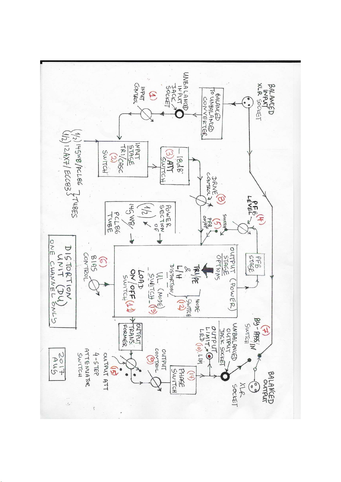
FRONT PANEL CONTROLS AND SWITCHES ................................................................................................ 9
OPERATING CONTROLS FROM LEFT TO RIGHT AND THEIR FUNCTION .................................................. 9
PREPARATION BEFORE SWITCHING ON ................................................................................................... 13
(1) PLACEMENT ................................................................................................................................... 13
(2) GROUND LIFT SWITCH .................................................................................................................. 13
(3) STAND-BY SWITCH ....................................................................................................................... 14
FIRST TIME SWITCHING ON ...................................................................................................................... 14
(4) The output attenuation switch ........................................................................................................ 15
(5) Inputs, outputs & BY-PASS rotary switch (6) .............................................................................. 15
PRECAUTIONS ............................................................................................................................................ 16
BIAS CONTROL AND HOW IT AFFECTS DISTORTION AND CLIPPING IN THE OUTPUT STAGE ....... 17
HOW TO USE THE BIAS CONTROL (6) IN TRIODE ULTRA-LINEAR AND PENTODE MODES ......... 18
SWITCHING ON ...................................................................................................................................... 20
TESTING THE UNIT AND OPERATING GUIDELINES ................................................................................... 21
CASCODE versus TRIODE ................................................................................................................... 22
TECHNICAL NOTES ..................................................................................................................................... 30
SAFETY .................................................................................................................................................... 30
GROUND LOOPS ................................................................................................................................ 30
GROUND LIFTING ............................................................................................................................... 30
BALANCED AND UNBALANCED LINES............................................................................................... 31
TUBE ISSUES ...................................................................................................................................... 32
NOISE, MICROPHONY & AGE ............................................................................................................ 32
MICROPHONY TEST ........................................................................................................................... 32
EMISSION LOSS ................................................................................................................................... 33
IONIZATION ........................................................................................................................................ 34

AAE Distortion unit
3
HOW OFTEN AND WHEN IS IT NECESSARY TO REPLACE TUBES .................................................... 34
FUSES ................................................................................................................................................... 35

AAE Distortion unit
4

AAE Distortion unit
5
DESCRIPTION & FEATURES
The signal that enters this Distortion Unit (DU) can be adjusted to produce a wide variety of clean,
mildly or excessively distorted sounds. This is an analogue sound processor and familiarity of the
unit and experimentation by the user are essential in creating a particular 'tone signature'.
Input and output stages
The unit has balanced and unbalanced inputs and outputs but only one input or output can be
used at a time.
The DU consists of an input stage and an output stage. The signal level that enters the input stage is
set by the input gain control, and the output signal level is set by an output control plus an
attenuator. Vacuum tubes are used all throughout the signal chain, except the input balanced to
unbalanced converter and the positive feedback stage. The balanced (XLR) input can accept a signal
of an amplitude of 6.4VRMS (18dBu) maximum, and this signal level must not be exceeded.
The DU has been designed to accept standard studio input signal levels of between 0.775VRMS
(OdBu) to 1.228VRMS (+4dBu), and its input impedance is 50k. It can also accept lower level signals
but if high distortion levels are desired the INPUT control and other level controls must be set higher
than usual. The input impedance of the equipment that the DU is connected too must not be less
than 2K.
The input stage can operate in two modes triode or cascode. Cascode is a low noise pentode made
out of two triodes (=CASCaded triODE).
The output of the input stage can be attenuated if necessary before it is fed to the drive
control. This enables a finer adjustment of the signal that enters the output stage and makes it easier
to blend the tone created by the two stages for mild coloration purposes instead of hard distortion.
The signal from the drive control is fed to the output stage which is a Single Ended (SE) mini power
amp using the power section of the PCL86/14GW8 triode/pentode tube and can be set to work
in triode, ultralinear and pentode low or high distortion modes.
One of the factors that affect the output distortion is how high the drive control is set, and the output
of the unit must always be reduced each time the drive control is set high for more distortion. The
output stage is centred around a high quality 1492s SOWTER output transformer.
The output stage also has a bias control that sets the amount of DC current that flows through the
PCL86/14GW8 power tube and output transformer under idle (no signal) conditions. This gives great
flexibility in altering the shape of the output waveform, its symmetry and the way that it clips, see
relevant section. Clipping occurs when the signal's maximum output is constricted by an amplifier's
circuitry.

AAE Distortion unit
6
Distortion 'tone’ in relation to frequency
* The distortion of a signal composed out of two or more different frequencies sounds harsher than
the harmonic distortion of single notes (frequencies) and it is called Inter-Modulation (IM) distortion.
*Any type of distortion in the low single frequencies sounds smoother and "warmer" than distortion
in the mid frequencies.
* Mild Intermodulation (IM) distortion of low frequency notes can also sometimes generate
‘warmth’.
* Harmonic distortion in high frequencies (above a few kHz) in single frequency signals is difficult to
detect due to the range of the human hearing. However, IM distortion caused by high frequency
signals is detectable.
* The output transformer and the way it interacts with the power tube also generates distortion
especially in the low frequencies.
Differences between triode and pentode sound.
At low input signals triode mode produces predominantly second harmonic distortion which is more
musical. Drive and gain controls must be set low to drive the DU softly to avoid clipping if this kind
of sound coloration is desired. As the drive level is turned up, more distortion will be generated, first
low even, then low odd (like third) and a smaller amount of higher orders both even and odd,
until eventually clipping occurs.
In pentode mode distortion starts earlier, as far as the drive level is concerned. Pentode output will
produce more third and higher order odd harmonic distortion products, in addition to second and
higher even products. By overdriving the power stage in higher drive settings and with gain switched
high, harsh edgy sound and a boost in the high mids and treble occurs.
In ultra-linear mode the tube operates somewhere in the middle between triode and pentode. This mode
was widely used in 50's and 60's hifi’s, the sound is a bit more like in triode mode but with more volume
and a bit more distortion (odd harmonic too) especially in the low and high frequencies.

AAE Distortion unit
7
Off Load' mode operation
In 'off load' mode the load that is connected to the output of the DU is removed (reduced to zero)
and this alters the characteristics of the amplified sound wave, introducing high distortion that
is extreme, harsh and shrill. This mode can be switched on or off.
Positive feedback (PFB)
This feature is also used for an extreme type of distortion where the DU output amplifier can
become unstable and in high PFB settings oscillate. This is because the output signal re-enters the
input of the output stage in such a manner (phase) so that it increases the amplification. This mode
can be controlled and switched on or off.

AAE Distortion unit
8

AAE Distortion unit
9
FRONT PANEL CONTROLS AND SWITCHES
(1) In the middle of the front panel (from top to bottom) and about two thirds of the distance from
left to right there is a large toggle switch labeled as S-BY/ON. When this switch pressed down (ON
position) it connects the high (B+) voltage lines from the internal power supply to the audio circuits
of the unit.
(a) The S-BY switch must be pressed down (ON) approximately one minute after you have
turned on the mains. The mains on/ off switch is at the back, situated next to the IEC mains input
socket. This delay is necessary to ensure that no high voltage is applied to the circuits until the
tubes have reached their operating temperature.
(b) This switch must also be used to disconnect the high voltage from the tubes every time you use
the (12) TRI L/H, PE L/H and the (13) UL mode switches, as discussed later.
(2) The red LED on the far left of the logo (on the center- line that separates the top and bottom
channels) which will light up as soon as the mains switch at the back is pressed on, and it indicates that
the mains has entered the unit and the tube filaments are lighting up.
(3) The green B+ LED on the same center-line on the right of the S-BY/ON switch that lights up when
the (B+) high voltage is connected to the audio circuits and the unit is ready to operate.
OPERATING CONTROLS FROM LEFT TO RIGHT AND
THEIR FUNCTION
THE BOTTOM CHANNEL IS THE MIRROR IMAGE OF THE TOP CHANNEL
(1) INPUT: this control adjusts the amount of signal that enters the input stage of the unit and it is
directly wired across the unbalanced (jack) input which is also the output of the balanced to
unbalanced converter stage. The position of this control enables the unit to accept a high range of
input signal levels.
The more you turn up the INPUT control the more harmonic and intermodulation distortion is
generated by the input stage.
This control has no effect on the amount of signal that enters the (XLR) balanced input
converter stage, but it adjusts the level coming out of the XLR input converter, and thus the signal
that enters the DU input stage.
The balanced to unbalanced converter does not amplify the signal, it has a gain of 0dB
(2) TRI/CASC: this switch selects the input stage operating mode. In the up position is triode (TRI) in
the down position is cascode (CASC) mode.

AAE Distortion unit
10
(3) ATT: an attenuation switch that when pressed down the signal level coming out of the input
stage is reduced by approximately 18 dBs.
(4) PFB: is the Positive Feedback control that adjusts the amount of in-phase signal that can re-enter
the input of the power stage and can be used to generate extreme distortion and/or oscillation.
(5) PFB ON: a switch that when pressed down the PFB effect comes on, when pressed up is off.
(6) BIAS: this control sets the amount of DC current that flows through the PCL86/14GW8 power tube
section. The higher this control is set the higher this DC current is.
(7) BY-PASS/IN: a two way rotary switch with a pointed knob; when this knob points to IN, and to do
that you must turn the switch clockwise the XLR output socket is connected to the output of
the unit so you get the DU processed sound. As far as the balanced XLR inputs and outputs are
concerned this is a true BY-PASS switch, but it only affects the balanced (XLR) input/outputs.
(8) DRIVE: it controls the signal level that enters the output power stage, and how hard the
output tube and transformer are being driven.
(9) OUTPUT: it adjusts the amount of signal that comes out of the unit and it works in conjunction
with the (15) OUTPUT ATT (output attenuator) rotary switch situated at the right end of the
front panel.
(10) LIM LED: it is situated right under the OUTPUT control on the top channel and right on top of the
OUTPUT control on the bottom channel.
This is the output limiter LED that lights up when the output signal coming out of the unit has reached
its maximum level of 6.7VRMS ,18.8dBu (approx.) and a hard clipping action takes place at the output
to stop any further signal increase in order to protect the equipment that the unit is connected to.
(11) LOAD ON/OFF: a large toggle switch; OFF LOAD (switch set in the UP position) is
an extreme harsh and shrill distortion effect when the output stage works in pentode (PE) mode,
especially in the high distortion setting.
In triode and ultra-linear modes the effect is more subtle and not as strong.
(12) TRI L/ H,PE L/H: a 4 step rotary switch that selects the mode that the output stage operates.
From left to right:
step 1: TRI L= TRIode Low distortion, the signal level in TRI/L is higher than in TRI/H mode.,
step 2: TRI H=TRIode High distortion, or to be more precise 'higher' distortion, because triode
mode offers mild coloration (more than serious distortion) and the difference in tone between
TRI L and TRI H is not huge anyway.
step 3: PE L= PEntode Low distortion
step 4: PE H= PEntode High distortion, and this mode has been especially designed for high
distortion, and the signal level in PE/H is higher than in PE/L

AAE Distortion unit
11
(13) UL: a large toggle switch that selects between triode and ultra-linear mode, situated on the left of
the MUTE switch.
(14) PHASE: a miniature toggle switch, it reverses the phase of the output signal.
(15) OUTPUT ATT this is a four-step rotary attenuator switch to extend the range of
the OUTPUT (9) control due to the fact that there can be a considerable variation of signal level that
the unit can generate.
Assuming that when this control is set in the fourth dot clockwise the output attenuation is 0db then
in the third dot clockwise it is -3dB, the second -6dB, first -12dB

AAE Distortion unit
12

AAE Distortion unit
13
PREPARATION BEFORE SWITCHING ON
Remove the protective plate which is screwed in front of the frontplate. The 10mm wrench for the
nuts is supplied but you will also need a flat screwdriver.
Carefully unscrew the top cover, make sure that all the tubes are firmly placed in their sockets. The
best way to do that is by holding them softly from the top tip and giving them a very gentle push
downwards to check that the pins are inserted all the way into the sockets. Also, if you softly hold
the tubes from the top tip and very gently move them from side to side a slight play (approx. 1/8"
in the tip area) is normal.
(1) PLACEMENT
* The location of the distortion unit (DU) is important.
* Its location/mounting must allow adequate air circulation from below, the sides and above it to
disperse the heat that the tubes/semiconductors generate.
Avoid hot locations such as near radiators or other heating units.
IF THE UNIT IS MOUNTED ON A RACK:
(a) If mounted on a rack ensure that the unit below it does not get
hot.
(b) Even if the unit below the DU runs cool, there must still be a distance of at least a 2U (3 1/2)
inches, 90mm) of empty air space between the DU and the unit below. If the unit below gets warm
this gap must be increased by least 4U (7 inches 18 ohm).
(c) Leave a 4U distance of empty air space between the DU and the unit that is on top of
it.
(d) both sides of the whole rack must be open to allow air passage.
(e) Also, if the unit is mounted on a rack it will need extra support from below due to its weight. A
sturdy rack shelf is suitable the 1" feet will allow air to enter from below.
Keep the top clear of items such as papers or anything that could block air passage and
cause overheating.
PLACE THE UNIT AWAY FROM SOURCES OF INTERFERENCE
(2) GROUND LIFT SWITCH
If this switch is used incorrectly the unit will become susceptible to interference, noise and hum.
Ensure that this switch which is situated in the rear panel is in the on position which is with the (I)
pressed down. This is to ensure that the metal case is connected to the negative signal ground of the

AAE Distortion unit
14
unit's electronic circuits so that it (the metal case) works as a shield against external interference but also
prevents internal instability and oscillation.
In most studios and especially if the balanced (XLR) inputs and outputs are used it may never be
necessary to operate this ground switch, so there is a piece of tape to keep it in the ON position at all
times.
If you need to operate this switch (see notes on ground lifting & loops) just pull the tape off.
It is important to remember that unless the case is shielded ( connected to the signal ground) by other
means if the GROUND LIFT SWITCH in is the off position the unit will be noisy.
(3) STAND-BY SWITCH
Ensure that the front panels stand-by switch (S-BY) is off, (the up position). This is because the
high voltage must not be applied to the tubes and the circuits until the tubes have warmed up.
FIRST TIME SWITCHING ON
If you switch on for the first time and until you get used to the unit:
(1) Set all controls for zero output and the switches for a low level output.
(a) Turn all controls and especially the OUTPUT (9) control fully anticlockwise, press the input
attenuation switch ATT (3) down (to reduce the drive to the output stage) and set
the TRI/CASC switch(2) in triode (TRI,up).
(b) Set the positive feedback PFB switch (5) off (up).
(c) Set the OFF/ON LOAD switch (11) in the ON LOAD position (down).
(d) Set the triode/pentode TRI/PE switch (12) in triode (TRI, L)
(e) Set the UL switch (13) in triode (TRI) mode (up).
(f) Set the phase switch (14) up for the output limit indicators LIM LED'S (10) to light up if the
maximum output signal limit has been reached.
(2) Insert an audio signal at the input and test one channel at a time
Connect an audio signal to the input of the first channel to be tested. The input can accept a wide
range of line level signal amplitudes, and offers ample gain adjustments.
However, for the following first tests I would recommend to use a source with an average
output of approximately 0.775Vrms/ 0dBu.
* The input of the unit can also accept old type domestic devices with an average line output
level of 0.3162VRMS/-7.8dBu. In this case the input gain settings must be higher than the ones I
recommend in the following paragraphs.

AAE Distortion unit
15
However, If the signal at the input is below the -7.8dBu level, the unit may not to be able to distort
as much.
* For input signal levels higher than the 0dBu level the INPUT control (1) may need to be set lower for
a clean sound.
(3) Connect the output of the unit to the LINE input of a mixer, a monitor amplifier or any device that
accepts studio line level signals. The input impedance of this device must not be less than 2K. A
simple monitor amplifier is the best choice for the first introductory tests.
(4) The output attenuation switch
If you are switching on for the first time, it is well advised to introduce this extra output
attenuation by setting this switch (15) fully anticlockwise in the first dot, in both channels.
The price to pay when this attenuation is applied is that for some clean low distortion settings
the output volume may be low but it is a price worth paying until you get to know how to control
the output level of the unit and how to reduce this output when it is necessary. This will be the
case for instance when you are overdriving the input stages or the output stages especially
in pentode (PE) and OFF LOAD mode to create serious distortion.
The setting of this switch also depends on the sensitivity of the equipment that you drive and you
may end up setting it in one position permanently once you get to know the unit.
(5) Inputs, outputs & BY-PASS rotary switch (6)
* Do not use the XLR (balanced) and JACK (unbalanced) inputs simultaneously.
* Do not use the XLR (balanced) and JACK (unbalanced) outputs simultaneously.
* In the BY-PASS (top) position the signal does not go through the unit at all, and the controls have
no effect so you will only get the original signal that you put in. This is because in the BY-PASS mode
the XLR output is directly connected to the XLR input.
* If you are using this switch please make sure that you do not change any settings while you are
on BY-PASS mode because there is big difference in output signal levels between different settings.
* The BY-PASS switch only works for the balanced (XLR) inputs and outputs. If you happen to use
the jack inputs or outputs or both and you set this switch on BY-PASS the signal will disappear.
* Please make sure to set it in the (IN) position at all times when either (jack) unbalanced input or
output or both are used per channel.
* Until you familiarize yourself with the unit and the various different output signal levels please keep
this switch on the (IN) position to avoid any errors.

AAE Distortion unit
16
PRECAUTIONS
PLEASE DO NOT LEAVE THE UNIT SWITCHED ON WHEN NOT IN USE
(1) Each time:
(a) you increase the input gain settings
(b) change from triode to ultra linear or pentode,
(c) operate in OFF LOAD mode
(d) operate in positive feedback (PFB) mode
Ensure that you decrease the OUTPUT (9) or the stepped attenuator OUTPUT ATT (15) controls so
that the output of the unit remains as constant as possible.
This is because when you overdrive the input or the output stages or you switch into a mode that
produces more distortion, it is not just the shape of the signal (and thus the sound) that changes but
also the amplitude of this signal.
For example the units output in pentode high distortion mode (PE,H) can be four times higher
(+12dB) than at the output at triode high distortion mode (TRI, H).
If you operate in OFF LOAD and PFB simultaneously the output signal can reach very high
levels indeed. The output of the unit is internally limited by an overload clipping circuit
(see (3) below). However, a high enough signal such as a loud buzzing noise caused by a faulty input
lead may damage an amp or speakers if the input gain levels as well as the OUTPUT (9) and
/or ATT (15) controls are set too high.
It is therefore best to start quietly and gradually turn the levels up so that you can keep control of the
units overall output level.
Careful use of the OUTPUT control (9) plus the (15) OUTPUT ATT (attenuator) rotary switch is very
important and necessary.
For instance when you operate in pentode high distortion (PE/H) mode and you overdrive the
output stage the output signal amplitude can reach very high values. You can set the OUTPUT

AAE Distortion unit
17
ATT (15) fully anticlockwise (first step) and use the OUTPUT(9) control to fine tune the level coming
out of the unit.
However, if the output of the unit is not high enough you can first turn the OUTPUT (9) control down
to zero then turn the OUTPUT ATT (15) switch one step clockwise (to attenuate less) and finally use
the OUTPUT (9) control to re-adjust.
Always turn the OUTPUT (9) control down to zero whenever you change anything and then gradually
turn it up again.
(2) If you are switching on for the first time and until you get to know the unit:
(a) Introduce extra output attenuation by setting the OUTPUT ATT (15) switch fully anticlockwise
(in the first dot) in both channels. You can always set this control higher later if the output volume is
low as you get to know the unit.
(b) Always turn the OUTPUT (9) control down to zero first and then turn it up to the required output
level.
(3) Ensure that output overload LED LIM (10) is always off, as soon as it lights up that means that
the maximum output limit has been reached.
For this LED to work the PHASE (14) switch must be set in the up position.
The restriction in the amplitude of the output signal is achieved by a clipping circuit. This clipping
is very hard, it does not sound good so as soon as this LED lights up please turn down
the (9) OUTPUT control.
(4) Always set the S-BY/ON switch on S-BY (up) before you use the TRI/PE (12) and/or
UL (13) switches and after you have used them press S-BY/ON down again (ON).
This procedure is explained in the 'THE OPERATING GUIDELINES' section.
BIAS CONTROL AND HOW IT AFFECTS DISTORTION AND CLIPPING IN THE OUTPUT
STAGE
The output stage has a bias control that sets the amount of DC current that flows through the power
tube and output transformer under idle (no signal) conditions. The lower this bias control is set
the higher the even harmonic distortion generated by the output stage will be.
When the power (output) stage is driven hard:
(1) One part (say for instance the top half) of the waveform clips because the output signal in the
power tube is entering its cut off region and this is called cut off clipping. This happens in all
three triode, ultra linear and pentode modes of operation.
* Cut off clipping is soft and builds up gradually.
(2) The other part (say for instance the bottom half) of the waveform clips because of:

AAE Distortion unit
18
(a) In triode mode :
An electrode at the input of this tube called the grid starts drawing current and this is called grid
clipping.
*Grid clipping in most control settings starts abruptly and is hard.
(b) In pentode mode:
(i) the same grid current effect that occurs in triode mode
(ii) the output signal in the power tube is entering its saturation region.
By the way, saturation clipping also takes place in triodes but not in the output amplifier circuit of this
DU.
*In most control settings in pentode mode saturation clipping is gradual and it coincides with grid
clipping . As a result this creates a softer clipping in this part of the cycle despite the harshness of the
grid current effect unless the tube operates in high bias currents where grid clipping takes place
before saturation.
* At certain settings in pentode mode you can create a symmetrical output waveform where both
parts of the signal 's cycle clip softly
(3) In ultra-linear mode the tube behaves like in triode mode (as far as clipping is concerned) unless it
operates in very low bias currents.
HOW TO USE THE BIAS CONTROL (6) IN TRIODE ULTRA-LINEAR AND PENTODE
MODES
(1) When the power stage is not driven hard
(a) At low BIAS settings
(i) The power output tube generates the highest amount of even harmonic distortion in all three
triode (TRI) ultra-linear (UL) and pentode (PE) modes
This type of distortion sounds ”warm" and musical and increases gradually at a rate proportional to
the signal level.
The least amount of distortion is generated in TRI,L mode.
(ii) The output stage distorts more at frequencies below 100Hz and especially around 30...40Hz and
this produces a "crunchy" bass sound.
This is due to the fact that the output transformer primary inductive reactance decreases and interacts
more with the tube at low bias currents.
(b) At high BIAS settings
(i) In triode (TRI) and ultra-linear (UL) modes the power tube will generate less distortion even in the
low frequencies.

AAE Distortion unit
19
(ii) Triode low distortion mode (TRI, L) when the BIAS (6) is set to 10 is the mode for the cleanest
sound possible, provided the drive signal is kept low enough not to cause grid
clipping (see (c) and (d) below).
(iii) In pentode mode the power tube produces not just even but also a fair amount of odd
"rougher" harmonic distortion.
(2) When the power stage is driven hard
(a) At low BIAS settings:
(i) In Triode Low distortion mode (TRI L on the MODE switch) and when the BIAS (6) is set
to zero, both grid clipping and cut off clipping occur at the same signal level, so
that the output waveform distorts symmetrically. As soon as the BIAS (6) is set above
zero, hard grid clipping appears first resulting in an asymmetrically distorted waveform.
(ii) In all other modes TRI (H) UL and PE (H=high or L=low distortion) soft cut off clipping takes
place first also resulting in an asymmetric waveform, rich in even harmonic distortion.
(iii) In pentode mode for hard grid clipping to occur the signal must be increased even further, well
after cut off clipping has taken place.
So at low BIAS settings and with careful use of the DRIVE (8) control (so that the signal entering
the power tube does not get too high) it is possible to operate the DU so that grid clipping does not
occur.
(v)There is more interaction between the output transformer and the power tube and that
generates a very characteristic distortion in the low frequencies, in all modes of operation, but
especially in pentode (PE) mode.
(b) At BIAS settings 3...7
(i) The waveform can be adjusted to take any shape in all modes except in triode low
distortion (TRI L).
(ii) In pentode (PE) low (L) or high (H) distortion modes grid clipping often coincides with the tube
entering its saturation region and it is nearly as soft and gradual as the cut off clipping in
the opposite half of the cycle.
By experimenting with both the BIAS (6) and DRIVE (8) controls you can generate
a symmetrical waveform that is clipped softly on both top and bottom half cycles.
In pentode high distortion mode (PE,)H with the BIAS (6) set to around 5 the waveform
clips symmetrically and softly in both half cycles.
(iii) The interaction between the output transformer and tube is not as high, but the stage
still generates low frequency distortion (but not as much as when the BIAS 6 is set low) especially
in pentode high distortion mode (PE,H)

AAE Distortion unit
20
(c) At maximum BIAS (=10)
(i) In triode and ultra-linear modes when the signal reaches a certain level grid clipping will
occur first which sounds harsh, and that happens well before cut off clipping.
The transition from a clean (TRI or UL) sound to grid clipping distortion is very abrupt, as already
mentioned in (1).
So to keep the sound clean you must set the DRIVE (8) control much lower and/or set the input
stage attenuator (ATT, 3) switch in the down position . The unit's output under these conditions may
be low, so the OUTPUT control (9) or the OUTPUT ATT switch(15) may have to be set higher.
(ii) In pentode, and especially in high distortion mode ( switch 12 set at PE,H) tube saturation and
the grid current effect interact with one another and as a result grid clipping is not as hard as in triode
and ultra-linear modes.
(iii) Low frequency distortion is the highest in pentode high distortion mode (PE,H).
SWITCHING ON
* Ensure that the S-By switch in the front panel is off, in the up position.*
*Connect the unit to the mains.
*Switch on the unit by pressing (down) the mains switch at the back, located next to the mains IEC
input.
*The red LED on the far left of the front panel will light up.
*Ensure that the BY-PASS switch (7) is in the IN (clock-wise) in both top and bottom
channels*
*Ensure that the OFF/ON LOAD switch (11) is in the ON LOAD (down) position
in top and bottom channels.
Also, in many applications the PFB mode will not be used, it is an extra feature for an extreme kind
of sound.
I would recommend not to use the PFB mode at first until you get to know the unit well enough, so for
the initial tests keep the PFB switch (5) up (off).*
After approximately 40 seconds press the S-BY (down, ON) to operate. The green B+ LED on
the left of the front panel will light up.
Ensure that the PHASE switch (14) is in the up for the output limit
indicators LIM LED'S (10) to light up if the maximum output signal limit has been reached. *
* See notes about FIRST TIME SWITCHING ON (1 a...f)
Table of contents
Other Argiriadis Analogue Electronics Recording Equipment manuals