Argo AWG15MH User manual

VRF SYSTEMS
WALL MOUNTED TYPE
INDOOR UNIT
Installation Manual
MODELS:
AWG15MH
AWG22MH
AWG28MH
AWG36MH
AWG45MH
AWG50MH
AWG56MH
AWG71MH
Thank you for choosing an Argoclima commercial air conditioner. Please read this manual carefully before using the unit and
retain it for future reference.
V 11/21

To Users
Thank you for selecting Argoclima product. Please read this instruction manual carefully
before installing and using the product, so as to master and correctly use the product. In order to
guide you to correctly install and use our product and achieve expected operating effect, we hereby
instruct as below:
(1) This appliance is not intended for use by persons (including children) with reduced physical,
sensory or mental capabilities, or lack of experience and knowledge, unless they have been
given supervision or instruction concerning use of the appliance by a person responsibility
for their safety.Children should be supervised to ensure that they do not play with the
appliance.
(2) In order to ensure reliability of product, the product may consume some power under
stand-bystatus for maintaining normal communication of system and preheating refrigerant
and lubricant. If the product is not to be used for long, cut off the power supply; please
energize and preheat the unit in advance before reusing it.
(3) Please properly select the model according to actual using environment, otherwise it may
impact the using convenience.
(4) This product has gone through strict inspection and operational test before leaving the
factory.In order to avoid damage due to improper disassembly and inspection, which may
impact the normal operation of unit, please do not disassemble the unit by yourself. You can
contact with the special maintenance center of our company ifnecessary.
(5) When the product isfaulted and cannot be operated, please contact with our maintenance
center as soon as possible by providing the following information.
1) Contents of nameplate of product (model, cooling/heating capacity,product date,
ex-factory No.).
2) Malfunction status(specify the situations before and after the error occurs).
(6) All the illustrations and information in the instruction manual are only for reference. In order
to make the product better, we will continuously conduct improvement and innovation. We
have the right to make necessary revision to the product from time to time due to the reason
of sales or production, and reserve the right to revise the contents without further notice.
(7) The final right to interpret for this instruction manual belongs to Argoclima.

Exception Clauses
Manufacturer will bear no responsibilities when personal injury or property loss is caused
by the following reasons:
(1) Damage the product due to improper use or misuse of the product;
(2) Alter, change, maintain or use the product with other equipment without abiding by the
instruction manual of manufacturer;
(3) After verification, the defect of product is directly caused by corrosive gas;
(4) After verification, defects are due to improper operation during transportation of
product;
(5) Operate, repair, maintain the unit without abiding by instruction manual or related
regulations;
(6) After verification, the problem or dispute is caused by the quality specification or
performance of parts and components that produced by other manufacturers;
(7) The damage is caused by natural calamities, bad using environment or force majeure.

Contents
1 Safety Notices (Please be Sure to Abide)........................................................ 1
2 Product Introduction .......................................................................................... 4
2.1 Outline of the Unit and Main Parts ............................................................................. 4
2.2 Rated Operating Condition ........................................................................................ 4
3 Preparations for Installation .......................................................................................... 5
3.1 Location for Installation............................................................................................................. 5
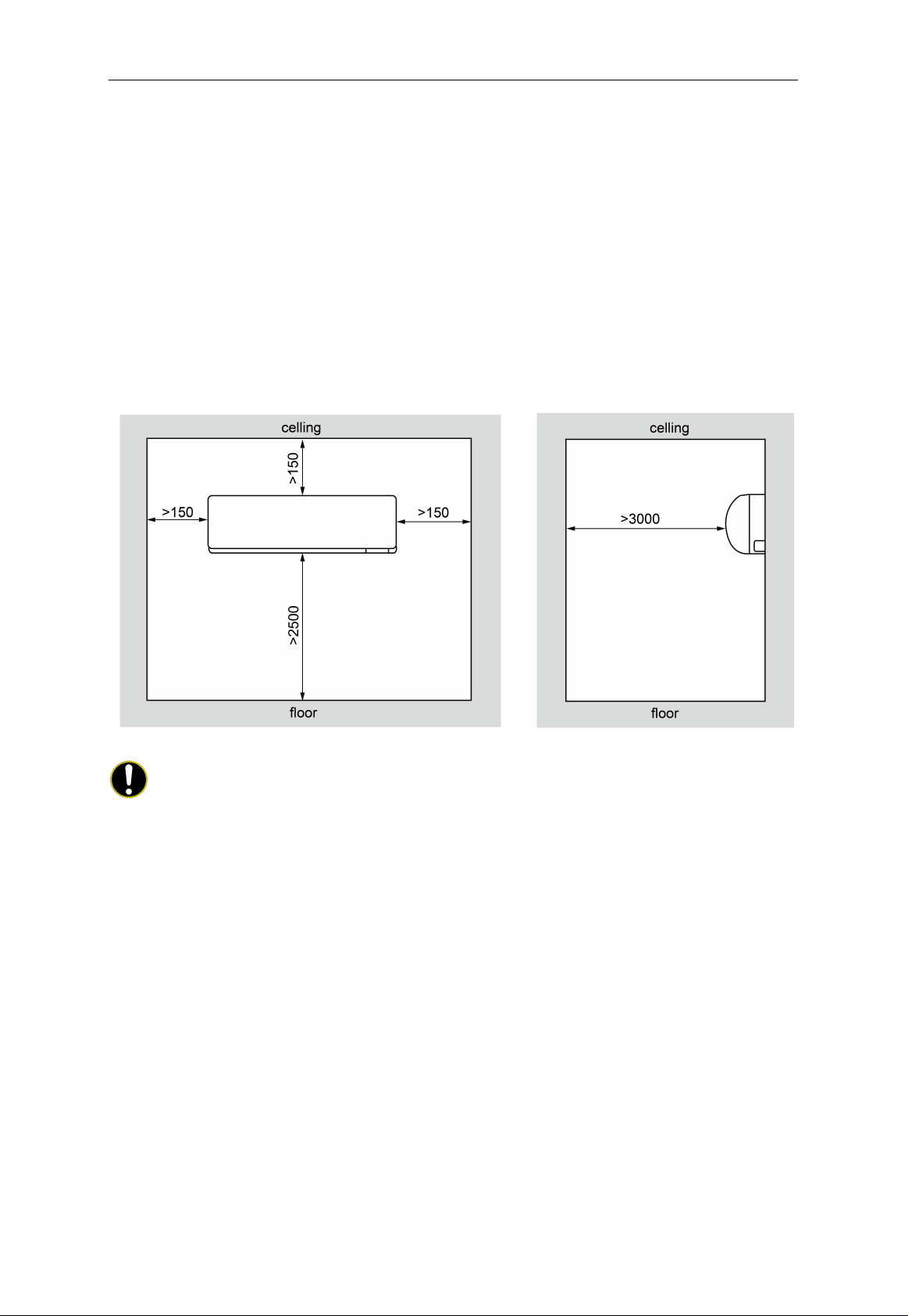
3.2 Schematic Diagram of Installation Space ............................................................................. 5
3.3 Requirements for Communication Line................................................................................. 6
3.4 Wiring Requirements................................................................................................................. 7
4 Installation Instructions................................................................................................... 8
4.1 Installation of Indoor Unit.......................................................................................................... 8
4.2 The Installation of the Rear Panel.......................................................................................... 9
4.3 Preparation of the Piping Hole ................................................................................................ 9
4.4 Installation of the Drainage Pipes........................................................................................... 9
4.5 Installation the Connection Pipes ......................................................................................... 10
5 Wiring Work....................................................................................................................... 11
5.1 Connect Cables and Terminals of Wiring Board ............................................................... 11
5.2 Power Cord Connection ......................................................................................................... 12
5.3 Connection of Communication Line of IDU and ODU ..................................................... 12
5.4 Connection of Communication Line of Wired Controller................................................. 13
5.5 Illuminate for Connection of Wired Controller and Indoor Units Network.................... 13
5.6 Installation of the Indoor Unit................................................................................................. 14
5.7 Connection of External Water Pump ................................................................................... 14
6 The Best Usage Method ................................................................................................ 16
7 Maintenance Method ...................................................................................................... 18
7.1 Cleaning Panel ......................................................................................................................... 18
7.2 Cleaning the Air Filters............................................................................................................ 18
7.3 Check Before the Usage Season ......................................................................................... 19
7.4 Check After the Usage Season............................................................................................. 19
8 Table of Error Codes for Indoor Unit ........................................................................ 19
9 Malfunction Analyzing ................................................................................................... 20
9.1 Service Center .......................................................................................................................... 20

9.2 After-Sales Service .................................................................................................................. 21
10 Adjusting Method of The Air Direction .................................................................. 21
10.1 Adjusting Air Direction Up and Down ................................................................................ 21
10.2 Adjusting Air Direction Left and Right................................................................................ 21

Multi Variable Air Conditioners Wall Mounted Type Indoor Unit
1
1 Safety Notices (Please be Sure to Abide)
WARNING! If not abide strictly, it may cause severe damage to the unit or the people.
NOTE!If not abide strictly, it may cause slight or medium damage to the unit or the
people.
This sign indicates that the ope
ration must be prohibited. Improper operation may
cause severe damage or death to people.
This sign indicates that the items must be observed. Improper operation may cause
damage to people or property.
WARNING!
This product can’t be installed at corrosive, inflammable or explosive environment or the
place with special requirements, such as kitchen. Otherwise, it will affect the normal
operation or shorten the service life of the unit, or even cause fire hazard or serious injury.
As for above special places, please adopt special air conditioner with anti-corrosive or
anti-explosion function.
This Multi VRF System shall only be connected to an appliance suitable for the same
refrigerant.
All units in Manual Cover is a partial unit, complying with partial unit of IEC
60335-2-40:2018, and must only be connected to other units that have been confirmed as
complying to corresponding partial unit requirements of this international standard.
The electrical interface shall comply with electrical security requirement, voltage shall be
220-240V(50Hz) or 208-230V(60Hz), current shall be referred to the table of “Wiring
Requirements” in Section 3.4, and safety class of construction is I.
NOTE!
(1)For evaporating units and condensing units, the instructions or markings shall include
wording to assure that the maximum operating pressure is considered when
connecting to any condenser unit or evaporator unit.
(2) For evaporating units, condensing units and condenser units, the instructions or
markings shall include refrigerant charging instructions.
(3)A warning to assure that partial units shall only be connected to an appliance suitable
for the same refrigerant.
(4)This unit is a partial unit air conditioner, complying with partial unit requirements of
this International Standard, and must only be connected to other units that have been
confirmed as complying to corresponding partial unit requirements of this
International Standard.
(5)The electrical interfaces shall be specified with purpose, voltage, current, and safety
class of construction.

Multi Variable Air Conditioners Wall Mounted Type Indoor Unit
2
Follow this manual to
complete the installation
work. Please read this
manual carefully before
turning on or repairing
the unit.
Installation should be
conducted by the dealer
or qualified personnel.
Please do not attempt to
install the air conditioner
by yourself. Improper
installation may lead to
water leakage, electric
shock or fire hazard, etc.
Before installation,
please check whether
the power supply is
complied with that
specified on the
nameplate and check
the safety of the power
supply.
The air conditioner must
be grounded reliably for
avoiding electric shock.
Please do not connect
the earthing wire to gas
pipe, water pipe,
lightning rod or
telephone line.
Be sure to use special
accessories and parts
for installation to prevent
water leakage, electric
shock and fire hazard,
etc.
If refrigerant leakage
happens, please
ventilate the room
immediately.
Diameter of power cord
should be large enough.
The damaged power
cord and connection
wire must be replaced
with special cables.
When the power cord is
connected, please fix
the electric box cover
properly to avoid safety
accidents.
Never fail to comply with
the nitrogen-charging
welding process. Do
charge nitrogen when
welding the pipes.
Never short circuit or
cancel the pressure
switch to prevent unit
damage.
As for the unit controlled
by the wired controller,
connect the wired
controller well firstly and
then energize the unit;
otherwise, the unit can’t
operate normally.
When installation is
finished, please check
whether the drainage
pipes, pipelines and
electric wires are
connected correctly to
avoid water leakage,
refrigerant leakage,
electric shock or fire, etc.

Multi Variable Air Conditioners Wall Mounted Type Indoor Unit
3
Do not insert fingers or
objects into air outlet or
air return grille.
Open the door and
window frequently to
keep good ventilation for
avoiding oxygen deficit
when gas heater or oil
heater is used in the
room.
Never plug in or unplug
the power plug directly
to turn on or turn off the
air conditioner.
Once the air conditioner
is turned on, it can be
turned off only after it
has operated for 5min at
least; otherwise, it will
affect the oil return of
compressor.
Do not allow children to
operate this air
conditioner.
Do not operate this air
conditioner with wet
hands.
The air conditioner can
be cleaned only when it
has been turned off and
the power has been cut
off; otherwise, it may
cause electric shock or
injury.
Never spray or flush
water towards the air
conditioner; otherwise,
malfunction or electric
shock may happen.
Do not expose the air
conditioner to the moist
or corrosive
environment.
Put through the power 8
hours in advance before
operation. Do not cut off
the power when the air
conditioner stops
operation for only about
one night (protect the
compressor).
Volatile liquid, such as
diluent or gasoline, will
damage the appearance
of air conditioner. Only
soft dry cloth and wet
cloth dipped with neutral
detergent can be used to
clean the outer case of
air conditioner.
Under cooling mode,
please don't set the
room temperature too
low; keep the
temperature difference
between indoor and
outdoor within 5°C
(41°F).

Multi Variable Air Conditioners Wall Mounted Type Indoor Unit
4
If there are any abnormal
circumstances (such as
burning smell, etc.),
please turn off the unit
and cut offthe main
power supply
immediately, and then
contact Argoclima
appointed service center.
If those abnormal
circumstances still exit,
the unit may be damaged
and it may lead to electric
shock or fire hazard.
Do not repair the unit by
yourself. Wrong
maintenance may cause
electric shock or fire
hazard.Please contact
Argoclimaappointed
service center for help.
Any personal injury or property loss caused by improper installation, improper debug,
unnecessary repair or not following the instructions of this manual should not be the
responsibility of Argoclima.
2 Product Introduction
2.1 Outline of the Unit and Main Parts
Fig 2.1
NOTE!
The appearances will be different by the different models of air conditioners.
No. Part Name No. Part Name
①Surface panel ④Guide louver
②Filter ⑤Drain pipe
③Wiring cover — —
2.2 Rated Operating Condition
Item
Indoor Condition Outdoor Condition
DBTemperature°C WBTemperature°C DBTemperature°C WBTemperature°C
Rated Cooling 27 19 35 24
Rated Heating 20 15 7 6

Multi Variable Air Conditioners Wall Mounted Type Indoor Unit
5
3 Preparations for Installation
3.1 Location for Installation
(1) The appliance shall not be installed in the laundry.
(2) The indoor unit should be installed at 2.5m or higher above the floor.
(3) The top holder must be strong enough to support unit’s weight.
(4) Drain pipe can drain water out easily.
(5) There is no obstacle at inlet or outlet. Please ensure good air circulation.
(6) Keep the unit away from heating source, inflammable gas or smoke.
3.2 Schematic Diagram of Installation Space
Unit: mm
Fig 3.1
NOTES!
①The unit shall be installed by the professional personnel according to this installation
instruction to ensure proper use.
②Please contact the local Argoclima appointed service center before installation. Any
malfunctioncaused by the unit that isnot installed by the Argoclima appointed service
center would probablynotbe dealt with on time because of the inconvenience of the
business contact.
③It should be guided under the professional personnel when the air conditioner unit is
moved to other place.
④Maintenance/service to be done by specialized personnel, mandated by the
manufacturer or authorized representative.
⑤This appliance is intended to be used by expert or trained users in shops,in
lightindustry and on farms or for commercial use by lay persons.
⑥This unit is a partial unitair conditioner, complying with partial unitrequirements of this
International standard and must onlybe connected to other units that have been
confirmed as complying to corresponding partial unitrequirements of this International

Multi Variable Air Conditioners Wall Mounted Type Indoor Unit
6
Standard.
⑦This unit shall only be connected to an appliance suitable for the same refrigerant.
3.3 Requirements for Communication Line
NOTE!
If the unit is installed in the place with strong electromagnetic interference, shielded wire
must be applied on the communication wire between indoor unit and wired controller. Twisted
pair line with shielding function must be applied on the communication wire between indoor unit
and indoor unit (outdoor unit).
3.3.1 Select communication line for indoor unit and wired controller
Fig 3.2
Material type
Total length of
communication line
between indoor unit and
wired controller L (m/feet)
Wire size
(mm2/AWG)
Material
Standard Remarks
Light/Ordinary
polyvinyl
chloride
sheathed cord.
(60227 IEC 52
/60227 IEC 53)
L≤250m
(L≤820-1/5feet)
2×0.75~
2×1.25
(2×AWG18~
2×AWG16)
IEC
60227-5-2007
1.Total length of communication
line can't exceed 250m
(820-1/5feet).
2.The cord shall be Circular cord
(the cores shall be twisted
together).
3.If unit is installed in places with
intense magnetic field or strong
interference, it is necessary to
use shielded wire.
3.3.2 Select communication line for indoor unit and indoor unit (outdoor unit)
Fig 3.3

Multi Variable Air Conditioners Wall Mounted Type Indoor Unit
7
Material Type
Total Length L (m/feet) of
Communication Cable
between Indoor Unit and
Indoor (Outdoor) Unit
Wire size
(mm2/AWG)
Material
Standard Remarks
Light/Ordinary
polyvinyl
chloride
sheathed cord.
(60227 IEC 52
/60227 IEC 53)
L≤1000m
(L≤3280-5/6feet)
≥2×0.75
(≥2×AWG18)
IEC
60227-5-2007
1. If the wire diameter is enlarged
to 2×1 mm2
(2×AWG16), the total
communication line
length can
reach 1500 m (4921-1/4feet).
2. The cord shall be Circular cord
(the cores shall be twisted
together).
3. If unit is installed in places with
intense magnetic field or strong
interference, it is necessary to
use shielded wire.
3.4 Wiring Requirements
Model Power Cord
Size
Air Switch
Capacity
(A)
Minimum
Sectional Area
of Ground
Wire(mm
2
)
Minimum
Sectional Area
of Power
Cord(mm
2
)
AWG15MH - AWG22MH - AWG28MH -
AWG36MH - AWG45MH - AWG50MH -
AWG56MH - AWG71MH
220-240V ~
50Hz
208-230V ~
60Hz
6 1 1
NOTES!
①Use copper wire only as unit’s power cord. Operating temperature should be within its
rated value.
②If the power cord is more than 15m, please increase properly the sectional area of
power cord to avoid overload, which may cause accident.
③Above selection requirements: Power cord size is based on BV single-core wire
(2~4pc) at 40°C ambient temperature when laying across plastic pipe. Air switch is D
type and used at 40°C.If actual installation condition varies, please lower the capacity
appropriately according to the specifications of power cord and air switch provided by
manufacturer.
④If the supply cord is damaged, it must be replaced by the manufacturer or its service

Multi Variable Air Conditioners Wall Mounted Type Indoor Unit
8
agent or a similarly qualified person in order to avoid a hazard.
⑤Install cut-off device near the unit. The minimum distance between each stage of
cut-off device should be 3mm (The same for both indoor unit and outdoor unit).
4 Installation Instructions
4.1 Installation of Indoor Unit
Fig 4.1
Below are dimensions of W, H, D for different models:
Unit: mm
Item
Model W H D
AWG15MH - AWG22MH, AWG28MH, AWG36MH 845 289 209
AWG45MH, AWG50MH 970 300 224
AWG56MH - AWG71MH 1078 325 246

Multi Variable Air Conditioners Wall Mounted Type Indoor Unit
9
4.2 The Installation of the Rear Panel
Unit: mm
Fig 4.2
①Find the horizontal position by the seton method; since the drainage pipe is on the left
side, it is necessary to adjust the rear panel to make its left side a little bit lower.
②Fix the rear panel on the wall by bolts.
③After installing the rear panel, pull it by hands to check if it is secured enough. The
hang panel should support the weight of an adult (60kg), and the weight shared by
every bolt should be fairly even.
④The diameter showed in Fig 4.2 is 55mm or 70mm.
4.3 Preparation of the Piping Hole
(1) Make the piping hole (Φ 55mm or 70mm) in the wall at a slight downward slant to the
outdoor side. The center of the hole should be determined referring to Fig 4.2.
(2) Insert the piping-hole sleeve into the hole to prevent the connected piping and wiring
from being damaged when passing through the hole.
4.4 Installation of the Drainage Pipes
(1) For proper draining, the drain hose should be placed at a downward sloping.
(2) Do not wrench or bend the drain hose or flood its end by water. (Fig.4.3)
(3) Wrap the drain hose with heat resistant material.
(4) It is not allowed to connect the condensate drain pipe into waste pipe or other
pipelines which are likely to produce corrosive or peculiar smell to prevent the smell
from entering indoors or corrupt the unit.
(5) It is not allowed to connect the condensate drain pipe into rain pipe to prevent rain
water from pouring in and cause property loss or personal injury.
(6) Condensate drain pipe should be connected into special drain system for air
conditioner.

Multi Variable Air Conditioners Wall Mounted Type Indoor Unit
10
Fig 4.3
4.5 Installation the Connection Pipes
Connect the ends of the connection pipe with two leading pipes, and then tighten the joint
nuts tightly.
Connect the connect pipe with the two relative leading pipe, tie the nut on tie –in of the
connect pipe tightly.
NOTES!
①Be careful in bending the connection pipes, or you would damage the pipes.
②If the tightening torque for the flare nut is too great, leakage would happen.

Multi Variable Air Conditioners Wall Mounted Type Indoor Unit
11
5 Wiring Work
WARNING!
Before obtaining access to terminals, all supply circuits must be disconnected.
NOTES!
①Units must be earthed securely, or it may cause electric shock.
②Please carefully read the wiring diagram before carry out the wiring work, incorrect
wiring could cause malfunction or even damage the unit.
③The unit should be powered by independent circuit and specific socket.
④The wiring should be in accordance with related regulations in order to ensure the
units reliable running.
⑤Install circuit breaker for branch circuit according to related regulations and electrical
standards.
⑥Keep cable away from refrigerant pipings, compressor and fan motor.
⑦The communication wires should be separated from power cord and connection wire
between indoor unit and outdoor unit.
⑧Adjust the static pressure via wired controller according to site circumstance.
5.1 Connect Cables and Terminals of Wiring Board
Connection of Wire and Patch Board Terminal
(1) The connection of wire (as shown in fig 5.1)
1) Strip about 25mm insulation of the wire end by stripping and cutting tool.
2) Remove the wiring screws on the terminal board.
3) Shape the tail of wire into ring by needle nose plier, and keep the gauge of ring in
accordance with screw.
4) Use the screwdriver for tightening the terminal.
(2) The connection of stranded wire (as shown in fig 5.2)
1) Strip about 10mm insulation of the end of stranded wire by stripping and cutting
tool.
2) Loosen the wiring screws on terminal board.
3) Insert the wire into the ring tongue terminal and tighten by crimping tool.
4) Use the screwdriver for tightening the terminal.

Multi Variable Air Conditioners Wall Mounted Type Indoor Unit
12
Unit: mm
Fig 5.1 Fig 5.2
5.2 Power Cord Connection
NOTE!
All indoor units must be unified of power supply so that they can be powered ON/OFF at
the same time.
If it’s with a plug, the power socket must be installed the place where is within your reach.
If the supply cord is damaged, it must be replaced by the manufacturer, its service agent
or similarly qualified persons in order to avoid a hazard.
That the appliance shall be installed in accordance with national wiring regulations.
This appliance incorporates an earth connection for functional purposes only.
Fig 5.3
For units with single-phase power supply.
(1) Detach the electric box lid.
(2) Let the power cord pass through the wiring through-holes.
(3) Connect the power cord to terminal "L, N, ".
(4) Fix the power card with wiring clamp.
5.3 Connection of Communication Line of IDU and ODU
(1) Open the cover of electric box of indoor unit.
(2) Lead the communication line across the rubber ring.

Multi Variable Air Conditioners Wall Mounted Type Indoor Unit
13
(3) Connect the communication line to terminal D1 and D2 on the 4-digit wiring board of
indoor unit, as shown in Fig 5.4(D1D2 Rated Voltage/Current 5V/100mA,ClassⅡ).
Fig 5.4
Fig 5.5
(4) Secure the communication line with the wire clamp on the electric box.
(5) In order to ensure the reliability of communication between IDU and ODU and the
communication among each IDU, add a matched resistance(supplied in a package
before ex-factory) on the wiring board of the last indoor unit in a series connection.
The matched resistance should be connected in parallel between terminal screw D1
and D2, as shown in Fig 5.5.
5.4 Connection of Communication Line of Wired Controller
(1) Open the cover of electric box of indoor unit.
(2) Lead the communication line of wired controller across the rubber ring.
(3) Connect the communication wire to terminal H1 and H2 of indoor 4-bit wiring board.
(4) Fix the communication wire with wire clip on the electric box.
5.5 Illuminate for Connection of Wired Controller and Indoor Units
Network
(1) Communication wire of indoor unit and outdoor unit (or indoor unit) is connected to
D1,D2.
(2) Wired controller is connected to H1,H2.
(3) One indoor unit can connect two wired controllers that must be set as master one and
slave one.
(4) One wired controller can control 16 indoor units in maximum at the same time.

Multi Variable Air Conditioners Wall Mounted Type Indoor Unit
14
NOTES!
①The type of indoor units must be the same if they are controlled by the same wired
controller.
②When the indoor unit is controlled by two wired controllers, the addresses of the two
wired controllers should be different through address setting. Address 1 is for main
controller; Address 2 is for slave controller. Detailed setting please refer to the
instruction manual of wired controller.
5.6 Installation of the Indoor Unit
(1) When routing the piping and wiring from the left or right side of the indoor unit, it is
necessary to cut off the tailings of the pipe left on the holder of the unit. (Shown in
Fig.5.6)
1) Cut down tailings 1 when only the power cord is led.
2) Cut down tailings 1,2 (or 1,2,3) when the connection cord and wire are led.
3) The piping types ①,②,③are recommended.
(2) Let the tubing and cord pass though the piping hole after tied up (refer to Fig .5.6 (d)).
(3) Hang the claw behind the indoor unit on the pothook on the wall panel, and move the
unit left and right to check if the body is firm.
(4) Guarantee that the installation height of the indoor unit should be 2.5m above the
floor.
Fig 5.6
5.7 Connection of External Water Pump
The external water pump applicable model:
AWG15MH, AWG22MH, AWG28MH, AWG36MH, AWG45MH,
AWG50MH, AWG56MH, AWG71MH

Multi Variable Air Conditioners Wall Mounted Type Indoor Unit
15
The external water pump is purchased by the user, and the water pump is selected
according to the requirements. The installation must be carried out by a professional according
to the local laws and regulations and the pump manual.
Main board terminal CN8: Provide power for the external water pump;power specification:
220-240V~50Hz,208-230V~60Hz; Power of water pump ≤30W; when there may be condensed
water according to the operating status of the indoor unit, the power will be turned on, and when
there is no condensed water, the power will be turned off.
Main board terminal CN35: It’s used to detect the water overflow error signal. When the
terminal CN35 is continuously disconnected for a certain period of time, the error code L3 of
water overflow error will be displayed on the indoor unit and the unit stops operation; when the
terminal CN35 is continuously connected for a period of time, the water overflow error will be
eliminated. When the user doesn’t need to use this function, the terminal CN35 shall be
connected according to the short circuit connection at the time of ex-factory.
Connection of external water pump and indoor unit
(1) Remove the panel.
(2) Remove the electric box cover.
(3) Connect the power cord of external water pump to the positions L and N of terminal
CN8 of the main board; connect the alarm wire to the positions 1 and 2 of terminal
CN35 (refer to Fig .5.7).
(4) Take out the wiring clip from the package of accessories. Remove the original wiring
clip from the electric box and secure the power cord and alerter wire with the new
clip.
This manual suits for next models
7
Table of contents
Other Argo Air Conditioner manuals