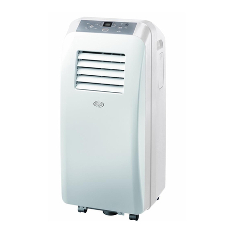
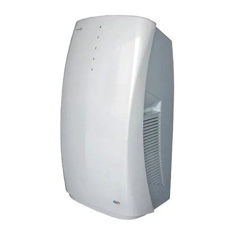
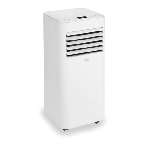
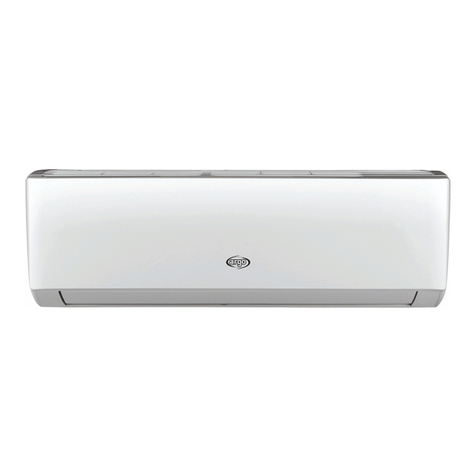
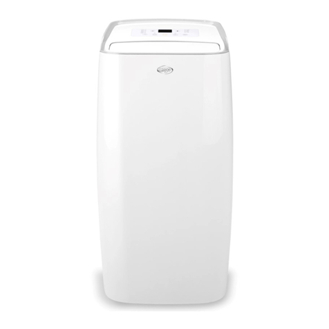
Argo DADOS 9 PLUS Operating manual

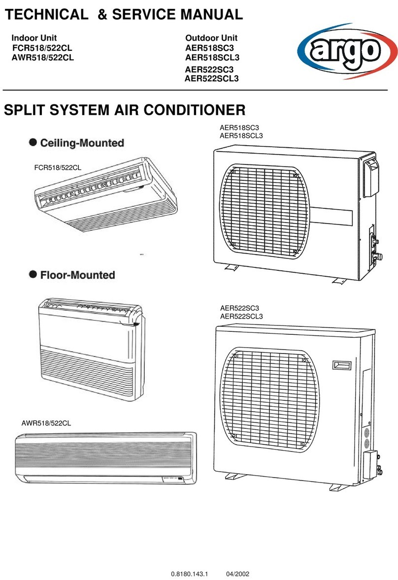
TECHNICAL & SERVICE MANUAL
dados 9 plus/13 plus/xl
V 10/2013

2
CONTENTS
1.Safety Precaution ……………………………………………………………............................................ 2
1.1 Installation ……………………………………………………………............................................... 2
1.2 Caution …………………………………………………………….............................................. 2
1.3 Operation ……………………………………………………………. ................................................ 2
2.Specification ……………………………………………………………........................................... 4
3.Outer Dimension …………………………………………………………… ........................................ 5
4. Refrigerant cycle diagram …………………………………………………............................................... 6
5.PCB drawing & wiring diagram ……………………………………………............................................. 7
6.Unit dissassembly sequence ………………………………………………………................................. 10
6.1 Casing Disassembly ………………………………………………………........................................... 10
6.2 Internal Parts Dissassembly ............................................................................................................. 13
7.Feature ............……………………………………………………………................................................. 16
7.1 Parts of the air conditioner ……………………………………………………… .................................. 16
7.2 Accessories …………………………………………………… .................................................... 17
8. Electronic Function …………………………………………………………… ........................................ 18
8.1 Function ……………………………………………………… ............................................................... 18
8.2 Controller Specifications ……………………………………………………… ...................................... 18
8.3 Controller Structure ……………………………………………………… .............................................. 18
8.4 Sensor Definitions ……………………………………………………… ................................................ 18
8.5 Mode ……………………………………………………… .................................................................... 18
8.6 Timer Setting ………………………………………………………........................................................ 20
8.7 Sleep ……………………………………………………… .................................................................... 20
8.8 Protection Function ……………………………………………………… .............................................. 20
9.Basic test procedure …………………………………………………………… ...................................... 23
9.1 Defective Compressor ……………………………………………………….......................................... 23
9.2 Sealed refrigeration repairs ……………………………………………………….................................. 24
9.3 Fan Motor ………………………………………………………............................................................. 26
9.4 Capacitor ………………………………………………………………… ............................................... 26
10.Characteristic of temperature sensor …………………………………… ............................................. 28
11. Trouble shooting …………………………………………………………… .......................................... 29
Appendix …………………………………………………………… ........................................................... 31
Trouble shooting problems …………………………………………………………… ................................ 31
Trouble shooting for electrical system ……………………………………................................................ 32

3
1. Safety precaution
1.1 Installation
For electrical work, contact the an authorized service center.
Do not disassemble or repair the product by yourself.
Sharp edges could cause injury, be especially careful of the case edges and the fins on the
condenser and evaporator.
Be sure the installation area does not deteriorate with age.
Take care to ensure that power cable could not be pulled out or damaged during operation.
Do not place anything on the power cable.
Do not plug or unplug the power supply plug during operation.
Do not store or use flammable or combustible gas near the product.
When there are flammable gas leaks, turn off the gas and open a window for ventilation before
turning the product on.
If strange sounds, or small or smoke comes from product, turn the breaker off.
When the product is soaked (flooded or submerged), contact an Authorized service center.
Pay attention that water does not enter the product.
Turn the main power off when cleaning or maintaining the product.
When the product is not in use for a long time, disconnect the power supply plug or turn off the
breaker.
1.2 Caution
Always check that there are not gas (refrigerant) leakage after installation, otherwise
please repair the product. After installing the drain hose make sure that water is
drained away properly. Install the product only on a flat surface.
Do not install the product in places where hot air outlet could damage the neighborhoods.
Use two or more people to lift and transport the product.
Do not install the product where it will be exposed to sea wind (salt spray) directly.
1.3 Operation
Do not expose the skin directly to cool air for long periods of time. (Do not sit in front of the air
outlet
). Do
not use the product for special purposes, such as preserving foods, works of art, etc.
Do not block the inlet or outlet of air flow.
Use a soft cloth to clean the air conditioner. Do not use harsh detergents, solvents, etc.
Do not touch the metal parts of the product when removing the air filter. They are very sharp.
Do not step on or put anything on the product.
Always insert the filter securely. Clean the filter every two weeks or more often if necessary.
Do not insert hands or other object through the air inlet or outlet while the product is
operated.
Do
not drink the water drained from the product.
Safety precautio
n

4
Replace the all batteries in the remote control with new ones of the same type. Do not mix old and
new batteries or different types of batteries.
Do not recharge or disassemble the batteries. Do not dispose of batteries in a fire.
If the liquid from the batteries gets onto your skin or clothes, wash it well with clean water. Do not
use the remote control when the batteries leak.
Safety precautio
n

5
Specification
2. Specification
Model DADOS 9 PLUS DADOS 13 PLUS DADOS XL
Nameplate
marking
Power
supply Ph-V-
Hz 1φ,220V-240V~50Hz
Cooling
Capacity W 2200/2300 2900/3000 3100/3200
Cooling Power
consumption W 820 1100 1100
Heating Power
consumption
W 625 925 960
Cooling
EER/COP W/W 2.70/3.70 2.60/3.10 2.80/3.30
System
data
Refrigerant
type
g R410A/430g R410A/620g R410A/805g
Design
pressure (Hi/Lo)
bar 33.5/10.5. 34.0/11.2 32.5/11.4
Moisture Removal(30°C,RH80%) L/DAY 30 50 55
air flow
(Hi/Mi/Lo)
m³/h 280/300/350 290/310/360 290/360/420
Noise level
(Hi/Mi/Lo)
dB(A) 40/37/38 42/39/38 48/43/40
Dimension&Weight
Dimension
(WxDxH) mm W500xD500xH540
Packing
(WxDxH) mm W570xD570xH660
Net/Gross
weight kg 29/32.7 32/36.3 34/38.5
System Details
Compressor Model KRRC072ELJC-A KA-C098ELBC-E
Type
Rotary
Capacity
W 1665W±5% 2268W±5%
Input
W 655W±5% 855W±5%
Rated
current(RLA)
A 2.85A±5% 3.8A±5%
Locked rotor
Amp(LRA)
A 21.1A±5% 20A±5%
Thermal
protector
B125-140-241C T0705/46
Capacitor
20uF 450V 25uF 450V
Refrigerant
oil
CC 240 300
Fan
Motor
Model
MD99-3 MD97-3
Input
W 85/44/32 138/113/92
Capacitor
5uF 450V
Lower speed Capacitor Mi N/A 10uF 450V 950Rpm
Lower speed Capacitor Lo N/A 15uF 450V 780Rpm
Speed(hi/mi/lo) ±50 Rpm 1030/830/730 1310/1220/1120
Evaporator
Number of
rows 2 3 3
Tube pitch(a)x row
pitch(b) mm 21x12.7
Fin
spacing FPI 18
Fin type
Hydrophilic
aluminum
Tube outside dimension type
Ф7 inner groove tube
Axial length x height x width
mm 317.7x336x25.4 317.7x336x38.1 317.7x336x38.1
Number of
circuits
2 2 2
Condenser
Number of
rows 2 3 4
Tube pitch(a)x row
pitch(b) mm 21x12.7
Fin
spacing FPI 18
Fin type
aluminum
Tude outside dimension type
mm
Ф7 inner groove tube
Axial length x height x width
mm 400x357x38.1 400x357x50.8 400x357x63.5
Number of
circuits
1 1 1
The standard
is EN14511 -2:2007
test condition is 35°C db/ 24°C
wb

6
Outer dimension
3. Outer dimension

7
Refrigerant cycle diagram
4. Refrigerant cycle diagram
The figure below is a brief description of the important components and their function in what is called the
refrigeration system

8
5. PCB drawing & wiring diagram
The below picture is PCB schematic:
800161-0Y-A-5-S-Q
The below picture is PCB Drawing
800161-0Y-A-5-S-Q
Motor plug
Remote control receiver
Button board
Micro switch plug Tempreature Sensor
1
1
2
2
3
3
4
4
5
5
6
6
7
7
8
8
D D
C C
B B
A A
Ti tle
Num ber Re visionSize
A3
Date: 2012-3-6 Sheet of
File: C:\Do c ume nts and Se tt ing s\.. \Q J-LDT B -A.SC HDra wn By:
Editio n
Appr ov al
Date
QJ- LDTB- A
DH/TE-
2012-01-03
FUSE
CC40
4
3
1
2
AC_N
AC_L
BUZZER
TNR 1
10.5V
3.15A 250V
D1-D4
+5V
IN4004
230V
C3
470uF/16V C2
104 C1
1000uF/25V
P1
P2
+12V
TRA N/OUT
561
TRA N/IN
JZC3
X108
+12V
0.1uF/275AC
P4
JZC2
12 V
C4
104
X109
C5
104
X105
X107
X104
X106
JZC4
JZC5
JZC6
JZC7
X103
JZC8
EI41-23
JZC1
X110
12345678
910111213141516
29
IC4
I1
O
3
G
2
I C1 - 7805
P11
8
8
7
7
6
6
5
544
33
22
11
IC5
30
X102
P16
JZC9
HEATER
1
1
2
2
3
3
4
4
5
5
6
6
7
7
8
8
9
9
10
10
11
11
12
12
13
13
14
14
15
15
16
16 17 17
18 18
19 19
20 20
21 21
22 22
23 23
24 24
25 25
26 26
27 27
28 28
29 29
30 30
31 31
32 32
DIP 32
U1
1
2
3
4
CN3
1
2
3
4
5
6
7
CN1
1
2
CN10
1
2
CN2
VCC 12 V
4.99 K
R9
51 0
R34
VCC
KEY
KEY
51 0
R14A P12
51 0
R13 P11
51 0
R12 P10
VCC 51 0
R4 P9
10 K
R5
VCC
VCC
10uF
C18 4. 99 K
R1
P31
VCC
4. 99 K
R2
10 uF
C17
P30
VCC P29
10uF
C16
VCC
510
R33
VCC
10K
R26
P27
P2
P3
P5
P6
P7
P8
P9
P10
P11
P12
P13
P14
P15
P16
P29
P30
P32
P31
P27
P26
P25
P24
P23
P22
P21
P20
P19
P18
P17
510
R33 Q1
RY8
P25
P24
P23
P22
P21
P20
P19
RY9
Q3
2K
R19
1 2
XTAL
XT1
27pF
Cap
C11
27pF
Cap
C12
22 K
R40
VCC
Diode 1N 40 07
D?
P5
1
2
3
KIA70 42 P
IC7
P8
P15
P16
2K
R8
VCC
VCC
104
Cap
C9
12 V
RY7
RY5
RY4
RY3
RY2
BUZ
RY1
2K
R11
BUZ
10 0
R10
12V
RY1
RY2
RY3
RY4
RY5
RY6
Q2
RY6
2K
R18
RY7
RY8
RY9
COMP
4WV
PUMP
OU T-M F
4WV
PUMP/LF
CN9-MF
OU T-HF
LF
MF
HF
CN9-HF
LF
MF
HF
15
R41
Water pump plug XL only 2way value plug XL only
LED board
PCB drawing & wiring diagram

9
The below picture is control logic drawing:
800194-0Y-1
The below picture is remote receiver logic Drawing:
800195-0Y-1
The below picture is display panel Drawing:
800196-0Y-1
PCB drawing & wiring diagram

10
Wiring Diagrams
630241-DY-12 for DADOS 9 & 13
630241-DY-13 for DADOS XL
PCB drawing & wiring diagram

11
6. Unit Disassembly sequence
Screws Position Quantity
1 Sharp-End Screws 4x12
Side panel/Front an back
panel/Upper cover/Electric
box/Metal bracket
60pcs
2 Double-End Screws 3x8 Light Setting Board 2pcs
3 Sharp-End Screws 3.5x10 Light Board/Receiver
Board/Button Board 7pcs
4 Truss-head Screws 4x10
Air-outlet/Main
PCB/Protecive cover of
motor/water pump
16pcs
5 Stainless Stell Screws
4x12 Evaporator end plate 4pcs
6.1 Step 1 - Casing Disassembly
Disassemble the casing from both left & right side
Extend both left and right side panel outwards, see below photo
Unit disassembly sequence

12
Take out the filter upwards, then unscrew the hot air louver.
Take out the filter upwards, then unscrew the hot air louver on the other side.
①
①
Unit disassembly sequence

13
Disassemble the case by easing the buttons in an upward direction, then to take it out outwardly.
Unscrew the front & back casing
①
Unit disassembly sequence

14
Disassemble the top casing
6.2 Step 2 - Internal Parts Disassembly
PCB Disassembly:
After disassemblying casings, please unscrew both sides of the cabinet to take out the PCB
①
Unit disassembly sequence

15
Disassembly steps for water motor :
please dismantle the screws of the condenser, slide up the partition panel.and then take out slow the
condenser from the left hand side. From there, you can see the water motor. Caution, please notice
that in order to avoid any water split by water wheel, you should uphold the condenser
Water motor Water wheel
Unit disassembly sequence

16
Motor Disassembly
Unscrew the top metal parts, to take out the polyfoam upwards
①
Unit disassembly sequence

17
7. Features
7.1 Parts of the Air Conditioner
Fix Led: Operation
Flash ON-OFF (1 sec. ON – 1 sec. OFF): Stand-By
Flash ON-OFF (1/6 sec. ON - 1/6 sec. OFF): Full Tank
DADOS 9/13
(1)
(9)
(7)
2
(1)
(10)
(9)
(2)
(7)
2
DADOS XL
Features

18
7.2 Accessories
Features

19
8. Electronic function
8.1 Function
8.1.1 Cooling , Heating or Dehumidifying mode
8.1.2 Auto switch on, off and sleep mode function
8.1.3 Ts range:Cooling:17~30°C;Heating:15~30°C (dados XL)
8.1.4 Time delay safety control
8.1.5 Auto Memory Function
8.2 Controller Specifications
8.2.1 Normal power source: 220VAC±15%
8.2.2 Operation temperature for electrical system:
- working temperature range:-10°C~+60°C
- storage temperature range:-20°C~+70°C
- relative humidity range:35~98%
8.2.3 Temperature sensor:R25/50=5K、B=3470 temperature precision:±1°C
8.3 Controller Structure
The control logic consists of remote control, indoor control panel, indoor main control panel. The output of main
control is including motor fan ( high, mid, low fan speed), compressor.
8.4 Sensor Definitions
TA: Temperature of ambient, (T1).
TE: Temperature of evaporator, (T2).
TS: Setting temperature, (T3).

20
8.5 Mode
8.5.1 Cooling
8.5.1.1 In cooling mode, set point temperature is 17~30°C;starting temperature is 25°C.
8.5.1.2 Cooling mode - compressor working condition:
A: Under the condition of T1 - T3 ≥+1°C, compressor will be running
B: Under the condition of T1 – T3 ≤+1°C, the unit will be switched off, compressor will be off too
Each time the compressor and internal motor system will be switching back to the original setting
Note: When compressor is off, cooling operation light is flashing. When the compressor is running, the operation
light will be turned on.
8.5.2 Dehumidification mode
8.5.2.1 During dehumidification mode fan system is in “low” setting and the compressor is working.
8.5.2.2 Dehumidification mode.
A. If indoor temperature ≤0°C, compressor will be off.
B. If 0°C<indoor temperature≤20°C,compressor will be on for 15 min and stop for 3 min.
C.If indoor temperature>20°Ccompressor will be on for 30 min and stop for 3 min.
Note: When compressor stops, the dehumidification indication light is on.
8.5.3 Heating mode (dados XL)
8.5.3.1 Heating mode: set point temperature range is 15~30°C,starting temperature is 20°C.
8.5.3.2 Heating mode, compressor working condition
A. Under the condition of T3 - T1≥+1°C(2°F)compressor will be turned on
B. Under the condition of T3 - T1≤+ 1°C(2°F)compressor will be turned off
Each time the compressor and internal motor system will be switching back to the original setting
Note: When compressor is off, cooling operation light is flashing. When the compressor is running, the operation
light will be turned on.
8.6 Protection function
8.6.1 Compressor delay protection
8.6.1.1 When the unit is switched on, the compressor needs 3 min and 30 s in order to start to operate.
This manual suits for next models
4
Table of contents
Other Argo Air Conditioner manuals

Argo
Argo POLIFEMO CLASS White User manual

Argo
Argo AEI1G65EMX User manual

Argo
Argo ASIAS8 User manual

Argo
Argo POLIFEMO FINN User manual

Argo
Argo ASR409VHG Manual

Argo
Argo FC52AL User manual

Argo
Argo AWR609CL User manual

Argo
Argo AFIAS11DC User manual

Argo
Argo dados 9/13 User manual

Argo
Argo FCR518CL Operating manual
Popular Air Conditioner manuals by other brands

LG
LG AB-H1208VA0 Service manual

Sanyo
Sanyo KS2432 instruction manual

Mitsubishi Electric
Mitsubishi Electric Mr.Slim MSZ-A24NA operating instructions

Friedrich
Friedrich WallMaster WS10 Installation and operation manual

OMAS
OMAS Air-Fi AFT7 Installer and User Instruction Manual

Toshiba
Toshiba RAV-RM561KRTP-E installation manual