Argo AFSI ECO 120SH3 User manual

Please read this manual carefully before installing and using the air conditioner, and
retain for future reference.
V 04/21
SERVICE MANUAL
SPLIT TYPE FLOOR-STANDING
AIR CONDITIONER
OUTDOOR UNIT INDOOR UNIT
AFSI ECO 120SH3 AFSI ECO 120HL

Table of Contents
Part Ⅰ: Technical Information.......................................................................1
1. Summary......................................................................................................................1
2. Specications..........................................................................................................3
2.1 Specication Sheet..................................................................................................3
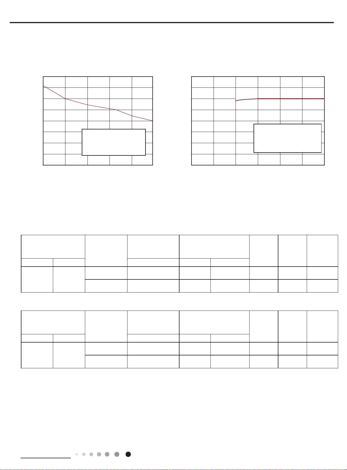
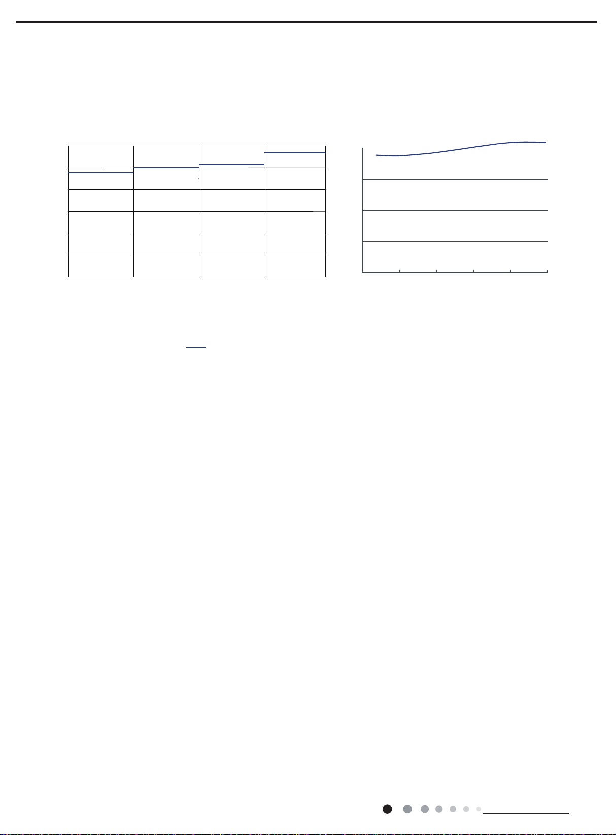
2.2 Capacity Curve in Different Outdoor Temperature.......................................7
2.3 Cooling Data Sheet in Rated Frequency..........................................................7
2.4 Noise Curve................................................................................................................8
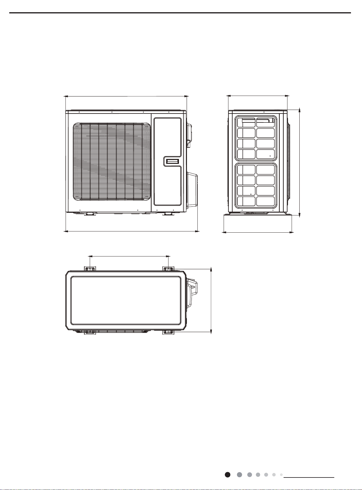
3. Outline Dimension Diagram........................................................................9
3.1 Indoor Unit..................................................................................................................9
3.2 Outdoor Unit.............................................................................................................10
4.
Refrigerant System Diagram......................................................................11
5.
Electrical Part..........................................................................................................12
5.1 Wiring Diagram .......................................................................................................12
5.2 PCB Printed Diagram............................................................................................14
6.
Function and Control........................................................................................16
6.1 Function Buttons of Air Conditioner...............................................................16
6.2 Remote Control Operations................................................................................18
6.3 Description of Each Control Operation..........................................................22
6.4Ewpe Smart App Operation Manual.................................................................24
Part Ⅱ : Installation and Maintenance .................................................25
7.
Notes for Installation and Maintenance...........................................25
8. Installation................................................................................................................29
8.1 Installation Dimension Diagram........................................................................29
8.2 Installation Parts-checking ................................................................................29
8.3 Selection of Installation Location.....................................................................29
8.4 Requirements for electric connection ...........................................................29
Table of Contents

Service Manual
8.5 Installation of Indoor Unit....................................................................................29
8.6 Installation of Outdoor Unit................................................................................33
8.7 Vacuum Pumping and Leak Detection............................................................35
8.8 Check after Installation and Test Operation.................................................35
9.Troubleshooting....................................................................................................36
9.1 Judgement by Flashing LED of Indoor...........................................................36
9.2 How to Check Simply the Main Part of Indoor ............................................39
9.3 How to Check Simply the Main Part of Outdoor.........................................49
9.4 Maintenance Method for Normal Malfunction..............................................51
10.Exploded View and Parts List...............................................................53
10.1 Indoor Unit..............................................................................................................53
10.2 Outdoor Unit..........................................................................................................55
11.Removal Procedure........................................................................................57
11.1 Removal Procedure of Indoor Unit................................................................57
11.2 Removal Procedure of Outdoor Unit.............................................................65
Appendix:........................................................................................................................69
Appendix 1: Reference Sheet of Celsius and Fahrenheit...............................69
Appendix 2: Configuration of Connection Pipe .................................................69
Appendix 3: Pipe Expanding Method.....................................................................70
Appendix 4: List of Resistance for Temperature Sensor................................71
Table of Contents

Service Manual
1
Technical Information
1. Summary
Part Ⅰ: Technical Information
AFSI ECO 120HL
Outdoor Unit:
AFSI ECO 120SH3
Remote Controller:

Service Manual
3
Technical Information
2. Specications
2.1 Specication Sheet
Parameter Unit Value
Model AFSI ECO 120HL-AFSI ECO 120SH3
Product Code
Power
Supply
Rated Voltage V~ 380-380
Rated Frequency Hz 50
Phases 3
Power Supply Mode outdoor
Cooling Capacity W 12500
Heating Capacity W 13500
Cooling Power Input W 3440
Heating Power Input W 3300
Cooling Power Current A 5.4
Heating Power Current A 5.2
Rated Input W 6600
Rated Current A 10
Air Flow Volume(SH/H/M/L/SL) m3/h 2400/2200/2000/1800/-
Dehumidifying Volume L/h 5
EER W/W 3.63
COP W/W 4.09
SEER W/W 6.1
SCOP W/W 4.0
Application Area m255-85
Indoor Unit
Model of indoor unit AFSI ECO 120HL
Product Code
Fan Type Centrifugal
Diameter Length(DXL) mm Φ379X180.5
Fan Motor Cooling Speed(SH/H/M/L/SL) r/min 600/560/530/500/-
Fan Motor Heating Speed(SH/H/M/L/SL) r/min 600/560/530/500/-
Output of Fan Motor W 220
Fan Motor RLA A /
Fan Motor Capacitor μF /
Evaporator Form Aluminum Fin-copper Tube
Pipe Diameter mm Φ7.94
Row-n Gap mm 3-1.5
Coil Length (LXDXW) mm 836X62X472
Swing Motor Model MP35AB/MP24TA
Output of Swing Motor W 2.5/1.5
Fuse A 5
Sound Pressure Level (SH/H/M/L/SL) dB (A) 57/55/53/51/-
Sound Power Level (SH/H/M/L/SL) dB (A) 68/-/-/-/-
Dimension (WXHXD) mm 587X1882X394
Dimension of Carton Box (LXWXH) mm 2150X735X530
Dimension of Package(LXWXH) mm 2153X738X545
Net Weight kg 57
Gross Weight kg 79.5

4
Technical Information
The above data is subject to change without notice; please refer to the nameplate of the unit.
Outdoor Unit
Model of Outdoor Unit AFSI ECO 120SH3
Product Code
Compressor Manufacturer/Trademark ZHUHAI LANDA COMPRESSOR
CO., LTD
Compressor Model QXFS-F428zX450I
Compressor Oil FW68DA or equivalent
Compressor Type Rotary
L.R.A. A 36
Compressor RLA A 8.2
Compressor Power Input W 4060
Overload Protector /
Throttling Method Electron expansion valve
Operation Temp ºC 16~30
Ambient Temp (Cooling) ºC -15~43
Ambient Temp (Heating) ºC -15~24
Condenser Form Aluminum Fin-copper Tube
Pipe Diameter mm Φ7.94
Rows-n Gap mm 2-1.4
Coil Length (LXDXW) mm 1052X38X792
Fan Motor Speed rpm 880
Output of Fan Motor W 150
Fan Motor RLA A 0.95
Fan Motor Capacitor μF /
Air Flow Volume of Outdoor Unit m3/h 6000
Fan Type Axial-ow
Fan Diameter mm Φ550
Defrosting Method Automatic Defrosting
Climate Type T1
Isolation I
Moisture Protection IPX4
Permissible Excessive Operating
Pressure for the Discharge Side MPa 4.3
Permissible Excessive Operating
Pressure for the Suction Side MPa 2.5
Sound Pressure Level (H/M/L) dB (A) 69/-/-
Sound Power Level (H/M/L) dB (A) 75/-/-
Dimension (WXHXD) mm 1028X822X530
Dimension of Carton Box (LXWXH) mm 1070X560X853
Dimension of Package(LXWXH) mm 1083X573X973
Net Weight kg 94
Gross Weight kg 105
Refrigerant R32
Refrigerant Charge kg 2.6
Connection
Pipe
Length m 5
Gas Additional Charge g/m 40
Outer Diameter Liquid Pipe 3/8
Outer Diameter Gas Pipe 5/8
Max Distance Height m 20
Max Distance Length m 30
Note: The connection pipe applies metric diameter.

Service Manual
7
Technical Information
2.2 Capacity Curve in Different Outdoor Temperature
2.3 Cooling Data Sheet in Rated Frequency
Instruction:
T1: Inlet and outlet pipe temperature of evaporator
T2: Inlet and outlet pipe temperature of condenser
P: Pressure at the side of big valve
Connection pipe length: 5 m.
Rated cooling condition(°C)
(DB/WB) Model
Pressure of gas pipe
connecting indoor and
outdoor unit
Inlet and outlet pipe
temperature of heat exchanger Fan speed
of indoor
unit
Fan speed
of outdoor
unit
Compressor
frequency
(Hz)
Indoor Outdoor P (MPa) T1 (°C) T2 (°C)
27/19 35/24 48K 0.9 to 1.1 in:8~11
out:11~14 in:75~85
out:37~43 Super High High 48
Rated cooling condition(°C)
(DB/WB) Model
Pressure of gas pipe
connecting indoor and
outdoor unit
Inlet and outlet pipe
temperature of heat exchanger Fan speed
of indoor
unit
Fan speed
of outdoor
unit
Compressor
frequency
(Hz)
Indoor Outdoor P (MPa) T1 (°C) T2 (°C)
20/- 7/6 48K 2.5 to 3.0 in:75~85
out:37~43 in:1~3
out:3~5 Super High High 68
Cooling:
Heaing:
Cooling Heating
Outdoor Temp.(°C) Outdoor Temp.(°C)
Capacity ratio(%)
Capacity ratio(%)
10 23 28
60
70
80
90
100
110
120
50
40 33 38 43
50
120
110
100
90
80
70
60
108-07-20
-30 -15
Conditions
Indoor: DB20°C/WB15°C
Indoor air flow: High
Pipe length: 5m
Conditions
Indoor: DB27°C/WB19°C
Indoor air flow: High
Pipe length: 5m

8
Technical Information
2.4 Noise Curve
60 65
60 80 100
50 55
40
45
40
30
35
20
25 20
10
00
Noise/dB(A)
low Middle
48K
High Super High
)A(Bd/esioN
Indoor side noise when blowing
Indoor fan motor rotating speed Compressor frequency/Hz
Outdoor side noise when blowing

9
Technical Information
AFSI ECO 120HL
Unit:mm
Model W H D
48K 587 1882 394
3. Outline Dimension Diagram
3.1 Indoor Unit

10
Technical Information
AFSI ECO 120SH3
Unit:mm
1028
610
944 460
530
822
490
3.2 Outdoor Unit

Service Manual
11
Technical Information
4. Refrigerant System Diagram
Indoor unit Outdoor unit
COOLING
HEATING
Accumlator
4-Way valve
COOLING
Discharge
Suction
Discharge
Suction
Heat
exchanger
(evaporator)
Heat
exchanger
(evaporator) Heat
exchanger
(condenser)
Valve
Valve
Valve
Valve
Liquid pipe
side
Gas pipe
side
Liquid pipe
side
Gas pipe
side
Compressor
Strainer
StrainerElectronic
expansion
Strainer
Capillary
Connection pipe specication:
Liquid : 1/4" (6 mm)24K
Liquid : 3/8" (9.52 mm)48K
Gas : 5/8" (16mm)

12
Technical Information
5. Electrical Part
5.1 Wiring Diagram
●Indoor Unit
● Instruction
Symbol Symbol Color Symbol Symbol Color Symbol Name
YE Yellow BN Brown COMP Compressor
RD Red BU Blue Grounding wire
YEGN Yellow/Green BK Black / /
AFSI ECO 120HL
5($&725
&
&$3
287'22581,7
1
6:,1*8' %8
;7
1
7(50,1$/
%/2&.
%.
$&/ %1
%8
%.
%1
<(*1
$3
35,17('&,5&8,7%2$5'
76(1625
7(03
5220
57 57
0
0
&20',63/$<
&200$,1
',63/$<
$3
$3
&1
0 <(*1
'&02725
3(
'&02725
6(1625
7(03
78%(
67(33,1*
6(1625
83'2:1
02725
/()75,*+7
67(33,1*
02725
&20
237,21$/
:,), &217$&7
6:,1*/5
&20287
3(
3(
0$*1(7,&
5,1*
/
<(*1
/
/
/
0$*1(7,&
5,1*
/%1
<(*1
/
3(
5' %1
1RWH0RWRUJURXQG
RQO\DSSOLHVWRWKH
LURQVKHOOPRWRU

13
Technical Information
● Outdoor Unit
These wiring diagrams are subject to change without notice; please refer to the one supplied with the unit.
AFSI ECO 120SH3
5'
<(
%8
:+
:+
%.
5'
%8
97
%8
+36 3
9<(
:5'
8%8 8
9
:
&203
(.9
:$<
/
%1
%. /
/
1
/
$3
0$,1%2$5'
;
;
;
;
),/7(5%2$5'
$3
;
;
;
;
%8
/
/
/
1
32:(5
1
%1
%.
97
/
/
97
%.
/
%1
;7
<(*1
%.
%8
,1'22581,7
%1
;7
+,*+35(6685(
9$/9(
(;3$16,21
(/(&7521,&
:$<
<9
9$/9(
)$ +33
9797
7(50,1$/
%/2&.
1
5($&725
)$102725
2)$1
0
3(
%1
%.
%8
76(1
7(50,1$/%/2&.
/
/
/
/
/
/
/
/
/
/
/
&20,1
3527(&7,21
6:,7&+
/%
5'
5($&725
/
/
/&
%. /
%8
<(*1
/;
3(
<(*1
3(
/
/;
/;
/; /;
0$*1(7,&
5,1*
/$
/; 5' /
%. /
/;
%8 /
/;
0$*1(7,&
5,1*
&203
0$*1(7,&
5,1*
0$*1(7,&
5,1*
;
3(
<(*1
3(
<(*1
LURQVKHOOPRWRU
RQO\DSSOLHVWRWKH
127(0RWRUJURXQG
1
%8
:$51,1*
3OHDVHGRQWWRXFKDQ\
HOHFWURQLFFRPSRQHQWRU
WHUPLQDOZKHQWKHPDFKLQH
LVUXQQLQJVWRSSLQJRU
KDVEHHQSRZHUHGRIIIRU
OHVVWKDQPLQXWHVWR
SUHYHQWHOHFWULFVKRFN
7(036(1625
(;+$867
7(036(1625
2875220
7(036(1625
28778%(
57
57
57 .
.
.

Service Manual
14
Technical Information
●Top view
●Bottom view
1 Interface of live wire
2 Fuse
3Interface of communication
wire for outdoor unit
4 Interface of netural wire
5 Motor interface of indoor unit
6 Interface of earthing wire
7Connection needle stand of
display board
8 Left&right swing interface
9 Up&down swing interface
10 Needle stand of temperature
sensor
1234
5
87
6
9
10
5.2 PCB Printed Diagram
Indoor unit

15
Technical Information
●Top view
1 2 3 4 5 6 7
8
9
10
11
1213141516
17
NO. Name NO. Name NO. Name
1Terminal of high pressure
protection 7Terminal of compressor
electric heating 13 Terminal of inductance
2Terminal of low pressure
protection 8 Terminal of 4-way valve 14 Terminal of neutral wire
3Terminal of compressor
overload protection 9 Terminal of outdoor fan 15 Terminal of communication
4Terminal of outdoor
temperature sensor 10 Terminal of power supply live
wire terminal 16 Reactor wiring terminal
5Terminal of electronic
expansion valve 11 Terminal of power supply
neutral wire 17 Compressor wiring terminal
6Terminal of electric heating
belt of chassis 12 Reactor wiring terminal /
Outdoor unit

Service Manual
16
Technical Information
6. Function and Control
6.1 Function Buttons of Air Conditioner
Button’s Name and Function
Introduction for icons on display screenof air conditioner
Timer
display Ambient temperature
or set temperature
display or others Operation
Cooling display
Dry display
Fan display
E-Heater display
Defrosting display
Heating display
Fan speed display
display
1
6
2
3
4
54FUNCTION button
2MODE button
MODE
3FAN button
FAN
FUNC.
1ON/OFF button
ON/OFF5▼/▲ button
6button
/
ON/OFF button
MODE button
1
2
FAN button
3
●
This series unit adopts touch buttons. You only need to touch the buttons slightly.
Press this button to turn on or turn off the unit.(Note: Under X-FAN mode, press this button to turn on the unit directly.)
●
Every time press this button, the mode will switchover in cycle among.
(Note: Cooling only unit won’t accept heating operation signal. For cooling only unit, pressing MODE button under FAN mode will
skip heating mode and enter cooling mode.)
COOLING DRY
HEATING FAN
●
Press this button and then fan speed can be selected and displayed in the
sequence as below:
(Note:Only low fan speed is available for dry mode. Fan speed can't be adjusted
under dry mode. Turbo cannot be set in FAN mode.)
(low) (medium) (high)
(turbo)
Note:
FUNCTION button
4
●
●
Under on status, press Function button to switch between timer and auxiliary heating function setting (auxiliary heating
can be set only in heating mode). When timer or auxiliary heating icon is blinking, it means this function can be set. Press
"▲" or "▼"
button to set function. If there’s no operation change within 5s after setting is finished, the function setting will be
confirmed. Or press Function button again to exit or confirm the function.When the function is selected through Function
button, if the unit is not turned off and no remote control signal is received within 2min, pressing Function button again to
circulate from the previous set function.After 2min or the unit is turned off or remote control signal is received, pressing
Function button again to circulate from timer icon. (Note: Only when the unit is under heating mode and with auxiliary heating
function, auxiliary heating function can be turned on or off through Function button.)
Under off status, if the unit is in X-FAN status, press Function button to turn off the unit directly; if the unit is not in X-FAN status,
press Function button to set timer ON.

17
Technical Information
Button’s introduction
Operation display
Timer display
● It indicates the air conditioner is
put through the power. Under on
Heating display
ƽ
When this indicator is on, it
indicates the timer function
is turned on.
status, this indicator is on; under
off status, this indicator is off.
●When this indicator is on, it
indicates the heating mode is
turned on.
●When this indicator is on, it
indicates the defrosting function
is turned on.
ƽ
●
●
When this indicator is on, it indicates
the dry mode is turned on.
When this indicator is on, it indicates
the cooling mode is turned on.
When this indicator is on, it indicates
the E-heater function is turned on.
●When this indicator is on, it indicates
the fan mode is turned on.
● Displays the fan speed. The fan speed
is displayed as below:
Dry display
E-Heater display
(only for the mode with this function)
Cooling display
Fan display
Icon function introduction
button
6
●
Left and right swing: this button controls the left and right swing motor, single press it to switchover between ON and OFF.
●
Up and down swing: this button controls the up and down swing motor, single press it to switchover between ON and OFF.
▼/▲ button
5
●
After each pressing of "▲" or "▼" button, set temperature will increase or decrease
auto mode. Timer setting can be set in 1h increment among 0~24h. When it is adjusted to
auxiliary heating function setting through Function button,press this button to turn on or turn off auxiliary heating. (Note: auxiliary
heating is valid only for the model with this function.)
1ć
. Temperature adjustment range is
ć~30ć. This button is invalid under
●
Hold "▲" and "▼" buttons for 3s and the air conditioner will display "LC", which indicates buttons are locked. Any button
under on status or ON/OFF button and function buttons under off status are all invalid. Hold these two button for 3s
again to release the lock.
Fan speed display
Defrosting display
(low) → (medium) →
(high) → (turbo)
/
16

Service Manual
18
Technical Information
6.2 Remote Control Operations
This is a general use remote controller, it could be used for the air conditioners with multifunction; For some function, which the
model doesn't have, if press the corresponding button on the remote controller that the unit will keep the original running status.
Buttons on remote controller
Introduction for icons on display screen
6
3
7
910
14
15
13
12
8
11
5
4
2
1
X-FAN function
Turbo fan speed
Quiet mode
Set fan speed
(No fan speed. It’s displayed
only after turning it on.)
{
Send signal
Switch temperature displaying type on
the unit’s display
Set time
TIMER ON/TIMER OFF
Child lock
Up & down swing
Left & right swing
battery power
Heat mode
Fan mode
Dry mode
Cool mode
Auto mode
Operation mode
I feel function
Sleep mode
WiFi This is a general remote controller.Some
models have this function while some
do not. Please refer to the actual models.
{
1ON/OFF button
2SAVE button
3FAN button
4MODE button
6
button
7
button
9
COOL button
14 LIGHT button
15 TIMER button
12
SLEEP button
13 QUIET button
10
HEAT button
8
X-FAN/E-HEATER button
11 WiFi button
5▲/ button
▲
Introduction for buttons on remote controller
●
After putting through the power, the air conditioner will give out a sound.
Operation indicator " " is ON.
●
Under on status, pressing the button on the remote controller, the signal icon " "
on the display of remote controller will
blink once and the air conditioner will give out a “di” sound, which means the signal has been sent to the air conditione
r.
After that, you can operate the air (This indicator is not available for some models).
conditioner by using remote controller.

19
Technical Information
ON/OFF button
1
SAVE button
2
Press this button can turn on or turn off the air conditioner. After turning on the air conditioner, indoor unit will give out a sound.
FAN button
3
Pressing this button can set fan speed circularly as: auto (AUTO), low( ), medium( ), high( ), turbo( ).
Auto
● It’s Low fan speed under Dry mode.
● Turbo cannot be set in FAN mode.
● Under AUTO speed, air conditioner will select proper fan speed automatically according to ex-factory setting.
Note:
Under cooling mode, press this button to start up or turn off energy-saving function.When energy-saving function is started up,
"SE" will be shown on remote controller, and air conditioner will adjust the set temperature automatically according to
ex-factory setting to reach to the best energy-saving effect. Press this button again to exit energy-saving function.
▲
▲/ button
5
● Press "▲" or " " button once increase or decrease set temperature 1ć(°F).
Holding "▲" or " " button, 2s later, set temperature
on remote controller will change quickly . On releasing button after setting is finished, temperature indicator on indoor unit will change
accordingly. (Temperature can’t be adjusted under
▲
▲
▲
● When setting TIMER ON, TIMER OFF, press "▲" or " " button to adjust time.(Refer to TIMER button for details)
auto mode)
● When selecting auto mode, air conditioner will operate automatically according to the sensed temperature. Set temperature
can’t be adjusted and will not be
displayed as well. Press "FAN" button can adjust fan speed. Press " " / " " button can adjust
fan blowing angle.
● After selecting cool mode, air conditioner will operate under cool mode. Cool
indicator " " on indoor unit is ON.
FAN" button to adjust fan speed. Press " " / " " button to adjust
fan blowing angle.
● When selecting dry mode, the air conditioner operates at low speed under dry
mode. Dry indicator " " on indoor unit is ON.
Under dry mode, fan speed can’t
be adjusted. Press " " / " " button to adjust fan blowing angle.
●When selecting fan mode, the air conditioner will only blow fan, no cooling and
no heating. Fan indicator " " on indoor unit is ON.
Press "FAN" button to adjust fan speed. Press" " / " " button to adjust fan blowing angle.
● When selecting heating mode, the air conditioner operates under heat mode.
Heat indicator " " on indoor unit is ON.
button to adjust set temperature. Press "F
AN" button to adjust fan speed. Press " " / " " button to adjust fan blowing angle.
unit won’t receive heating mode signal. If setting heat mode with remote controller, press ON/OFF button can’t start up the unit).
MODE button
4
Press this button to select your required operation mode.
AUTO COOL FANDRYHEAT
Note:
● For preventing cold air, after starting up heating mode, indoor unit will delay 1~5 minutes to blow air (actual delay time is depend on indoor
● Set temperature range from remote controller: 16~30ć(61-86°F);
Fan speed: auto, low speed, medium speed, high speed, turbo speed.
button to adjust set temperature. Press "
ambient temperature).
Cool button
6
● Press this button, unit will operate in cool mode.
● Press this button, unit will operate in heat mode.
Heat button
7
(This indicator is not available for some models).
"▲" or " "
▲
▲
Press
"▲" or " "
Press
(Cooling only

Service Manual
20
Technical Information
● Under simple swing mode, press this button can turn on (" " icon is displayed) or
turn off (" " icon is not displayed)
● When the unit is turned off by remote controller, press "▲" button and " "
● This remote controller is the general type remote controller. When remote controller receives the signal of " " , sw
ing
status is same as " " ; when remote controller receives " " , swing status is same as left&right swing OFF.
button can switch between single swing mode
" " on the remote controller will flash twice.
9
Under fixed-angle swing mode, press this button and then left&right swing status will
circulate as shown in the right figure:
● Under simple swing mode, press this button can turn on (" " icon is displayed)
lor turn off (" " icon is not displayed) the
● When the unit is turned off by remote controller, press "▲" button and " "
button can switch between single swing mode and
" " on the remote controller will flash twice.
Under fixed-angle swing mode, press this button and
the up&down swing status will circulate as shown in the right figure:
button
8
button
no display
no display
10 SLEEP button
Under COOL, or HEAT mode, press this button to start up sleep function. " " icon is displayed on remote controller
. Press this
button again to cancel sleep function and " " icon will disappear.After powered on, Sleep Off is defaulted. After the unit is
turned off, the Sleep function is canceled. In this mode, the time of time can be adjusted. Under Fan DRY and Auto modes,
this function is not available.
WiFi button
11
12
Pressing this button in COOL or DRY mode, the icon " " is displayed and the
Only under cooling mode and dry mode, press this button can turn on (characters
(characters of “X-FAN” are not displayed)
of “X-FAN” are displayed) or turn off
X-FAN function.
indoor fan will continue operation for a few
minutes in order to dry the indoor unit even though you have turned off the unit. After energization, X-FAN OFF is
defaulted.X-FAN is not available in AUTO, FAN or HEAT mode.
unit will be blowed
This function indicates that moisture on evaporator of indoor
after the unit is stopped to avoid mould.
● Having set X-FAN function on: After turning off the unit by pressing ON/OFF
about a few minutes. at low speed.
button indoor fan will continue running for
In this period, press X-FAN button to stop indoor fan directly.
●
●
Under heating mode, press this button and the E-HEATER status will changed circularly as below:
●
Having set X-FAN function off: After turning off the unit by pressing ON/OFF
button, the complete unit will be off directly.
X-FAN/E-HEATER button(only for the mode with this function)
Auto E-HEATER (no display)
E-HEATER OFF
( is displayed)
E-HEATER ON
( is displayed)
the left&right swing function.
and fixed-angle swing mode.
up&down swing function.
fixed-angle swing mode.
Press " WiFi " button to turn on WiFi function, "WiFi " icon will be displayed on the remote controller;
Hold " WiFi " button for 5s to turn off WiFi function and " WiFi " icon will disappear.
Under off status, press "MODE" and " WiFi " buttons simultaneously for 1s, WiFi module will restore factory settings.
● This function is only available for some models.
This manual suits for next models
1
Table of contents
Other Argo Air Conditioner manuals

Argo
Argo SDIAS8DC User manual

Argo
Argo ASIAS8DC User manual

Argo
Argo KENNY EVO User manual

Argo
Argo AWIBS9DC User manual

Argo
Argo MAXIME PLUS EU User manual

Argo
Argo AEG ECO PLUS 35PIH User manual

Argo
Argo KENNY EVO User manual

Argo
Argo ASIAS8 User manual

Argo
Argo AUR210CL Series Manual

Argo
Argo GREENSTYLE PLUS DUAL 9000 UI User manual