Page 2-2 Rev. 0040322000 3413
Operating and installation instructions
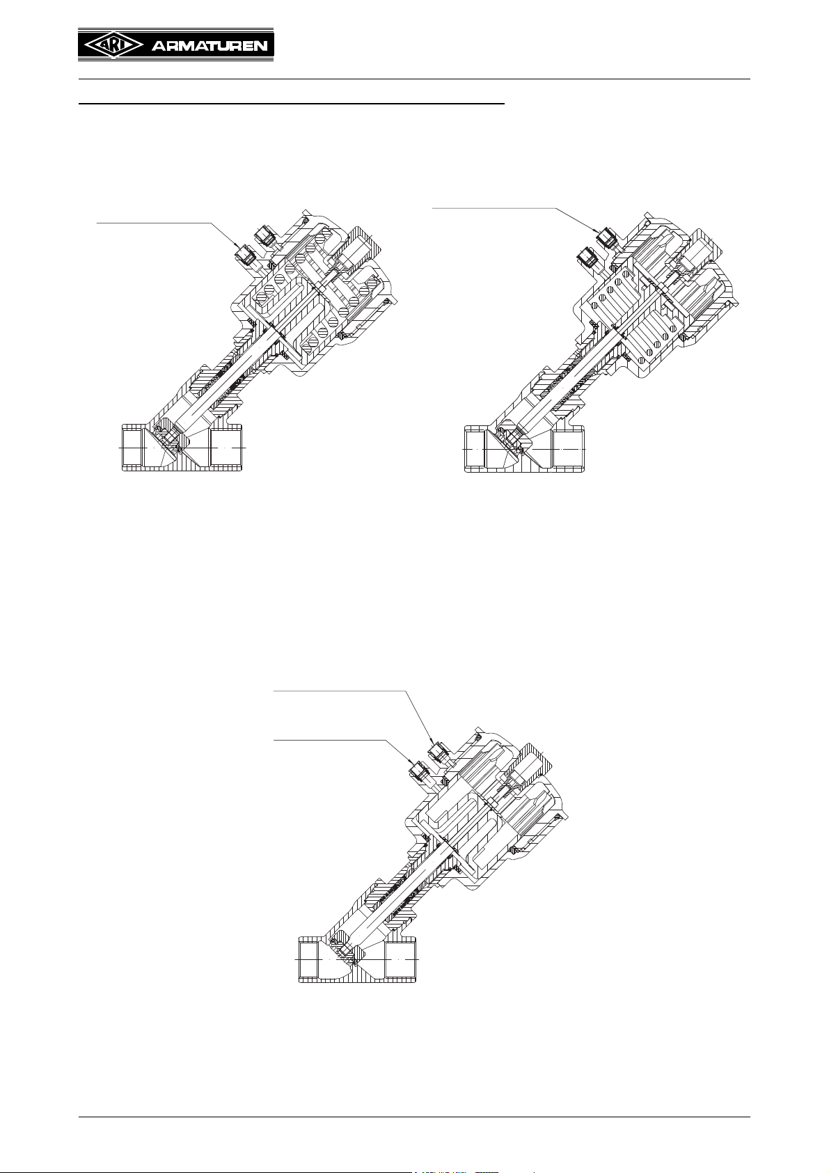
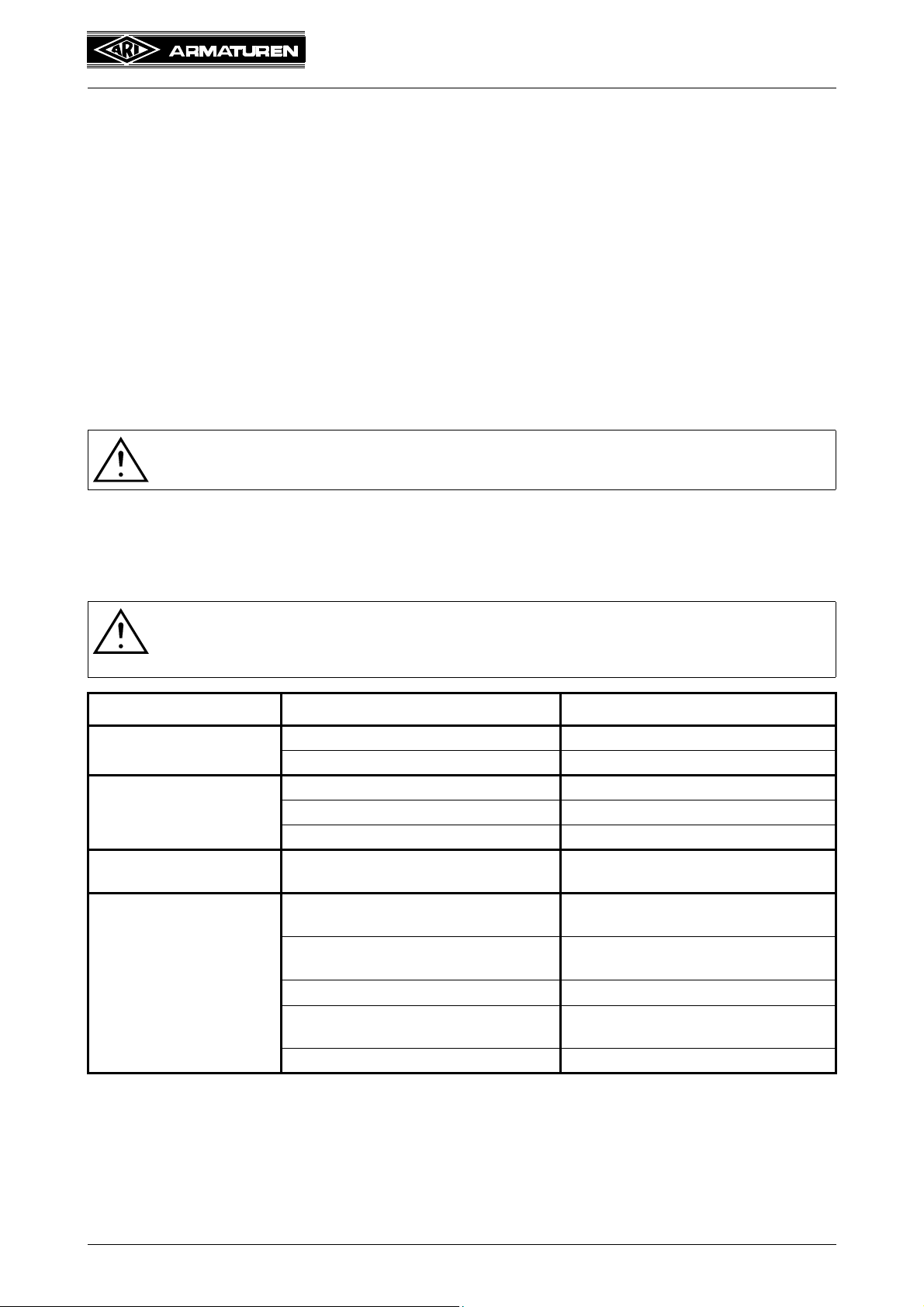
Y-pattern processing valve - STEVI®AS 350
1.0 General information on operating instructions
These operating instructions provide information on mounting and maintaining the fittings.
Please contact the supplier or the manufacturer in case of problems which cannot be
solved by reference to the operating instructions.
They are binding on the transport, storage, installation, start-up, operation, maintenance
and repair.
The notes and warnings must be observed and adhered to.
- Handling and all work must be carried out by expert personnel or all activities must be
supervised and checked.
It is the owner’s responsibility to define areas of responsibility and competence and to
monitor the personnel.
- In addition, current regional safety requirements must be applied and observed when
taking the fittings out of service as well as when maintaining and repairing them.
The manufacturer reserves the right to introduce technical modifications at any time.
These operating instructions comply with the requirements of EU Directives.
2.0 Notes on possible dangers
2.1 Significance of symbols
2.2 Explanatory notes on safety information
In these operating and installation instructions dangers, risks and items of safety
information are highlighted to attract special attention.
Information marked with the above symbol and “ATTENTION ! ” describe practices, a
failure to comply with which can result in serious injury or danger of death for users or third
parties or in material damage to the system or the environment. It is vital to comply with
these practices and to monitor compliance.
All other information not specifically emphasised such as transport, installation, operating
and maintenance instructions as well as technical data (in the operating instructions,
product documentation and on the device itself) must also be complied with to the fullest
extent in order to avoid faults which in turn can cause serious injury to persons or damage
to property.
3.0 Storage and transport
- At -20 °C to +65 °C.
ATTENTION !
. . . Warning of general danger.
ATTENTION !
- Protect against external force (like impact, vibration, etc.).
- Valve mountings such as actuators, handwheels, hoods must not be used to
take external forces, e.g. they are not designed for use as climbing aids, or as
connecting points for lifting gear.
- Suitable materials handling and lifting equipment should be used.
See catalog sheet for weights.