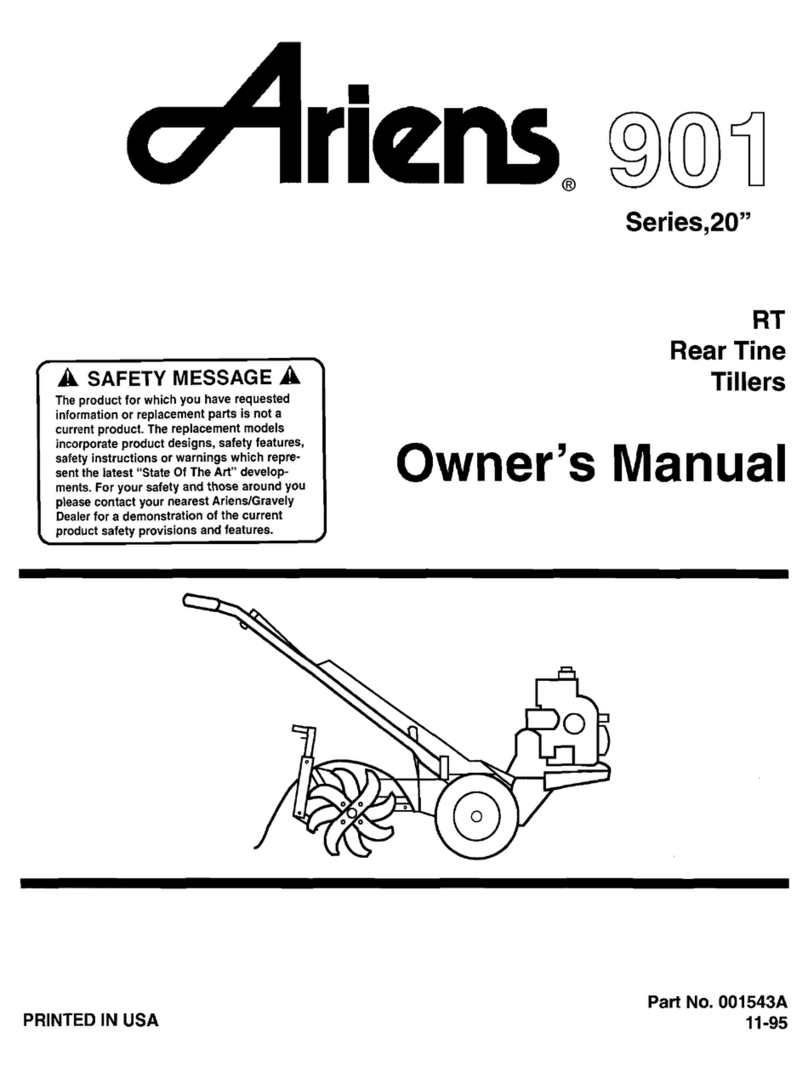
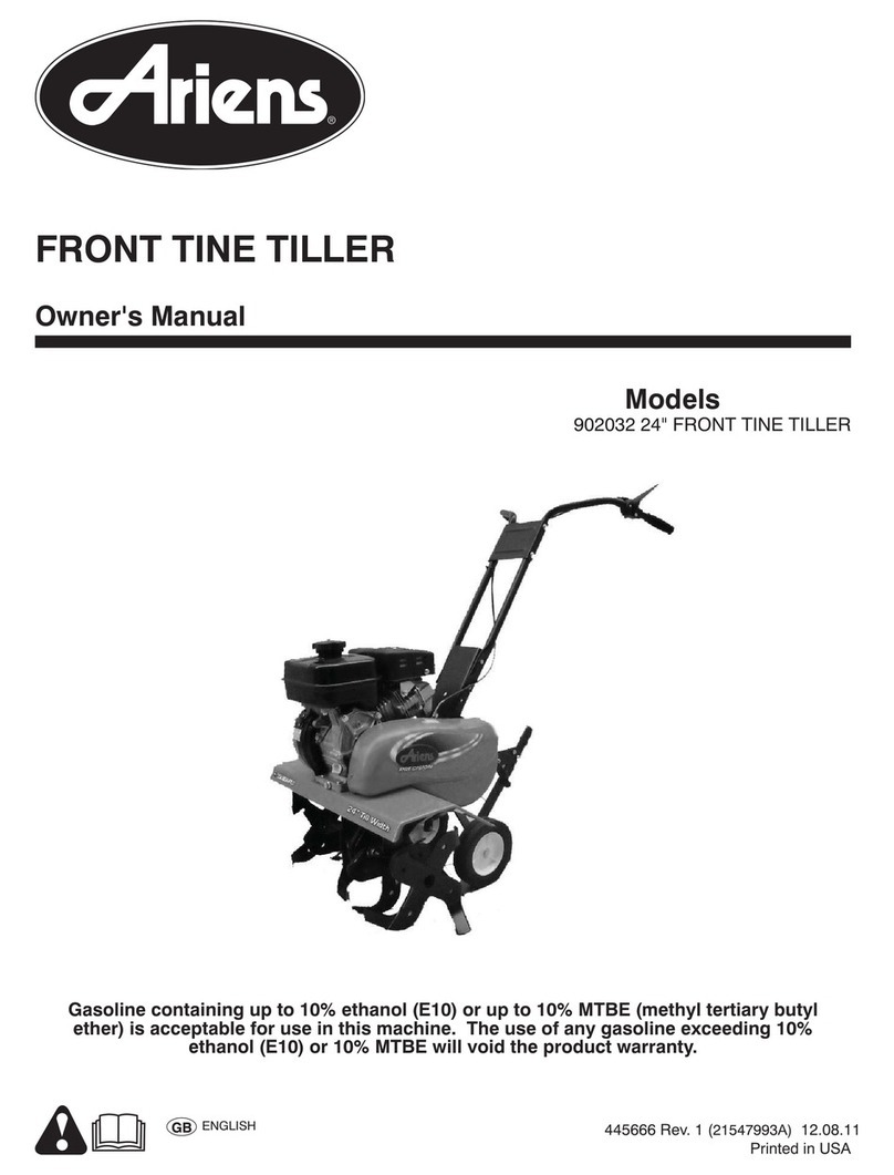
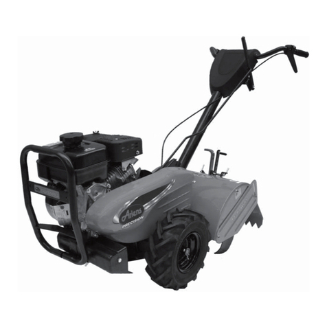
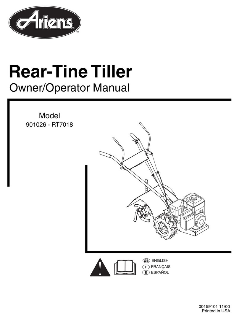
Ariens Rocket 901 Series Owner's manual

00158400A Orig. 5/98
Supercedes 00158400
Printed in USA
Owner/Operator Manual
Rocket™Rear-Tine Tiller
MODEL
024 - RT8020
901901901
SERIESSERIESSERIES
RTRTRT802080208020

i
A Message to Ariens Customers . . .
Welcome to the world of Ariens equipment. We are
pleased that you have purchased the best equipment
available. The care you give your new Ariens
equipment will determine the satisfaction and service
life you will obtain from it. Use this manual and the
engine manual supplied, as your guide. By observing
the instructions and suggestions in these manuals,
your Ariens equipment will serve you well for many
years.
Your Ariens dealer will be happy to supply any
service or advice which may be required to keep your
Ariens equipment operating at peak efficiency. The
dealer stocks genuine Ariens parts and lubricants;
manufactured with the same precision and skill as the
original equipment. A factory trained staff is well
informed on the best methods of servicing Ariens
equipment.They are ready and able to serve you.
If engine repairs or services are required, they can be
obtained from an Ariens dealer or from an authorized
engine manufacturer’s service center. If service is
required, be prepared to supply the service person
with the Model Number and Serial Number of the
equipment and the engine, as well as a full
description of the problem encountered.
NOTE: The descriptions and specifications
contained in this manual were in effect at the time the
manual was approved for printing. Ariens Company
reserves the right to discontinue models without
notice and without incurring obligation. The
equipment described within this manual may not be
identified as either standard or optional and the
various illustrations may not all be applicable to your
particular tiller. If you have questions, always check
with your Ariens dealer.
Safety Alert Symbol and Notations
The following safety notations are used throughout
this manual to call attention to special information or
operating procedures. Understand the message in
each notation and be alert to unsafe conditions and
the possibility of personal injury.
NOTE: A NOTE points out general reference
information regarding proper operation and
maintenance practices.
IMPORTANT: An IMPORTANT statement indicates
specific procedures or information that is required to
prevent damage to the machine or its attachments.
This safety alert symbol is used to
attract your attention! PERSONAL
SAFETY IS INVOLVED! When you see
this symbol - BECOME ALERT - HEED
ITS MESSAGE.
WARNING: A WARNING describes a
condition where failure to follow the
instructions could result in severe
personal injury.
DANGER: A DANGER designates a
condition where failure to follow
instructions or heed warning will most
likely result in serious personal injury
or death.
CAUTION: A CAUTION identifies safe
operating practices or indicates unsafe
conditions that could result in personal
injury.
WARNING
The engine exhaust from this product
contains chemicals known to the State of
California to cause cancer, birth defects or
other reproductive harm.
OL0010

1
Contents Model
Safety Alert and Notations . . . . . . . . . . . . . . . . . . . .i
Safety Precautions . . . . . . . . . . . . . . . . . . . . . . . . .1
Safety Decals . . . . . . . . . . . . . . . . . . . . . . . . . . . . .3
Controls and Features . . . . . . . . . . . . . . . . . . . . . .4
Operation . . . . . . . . . . . . . . . . . . . . . . . . . . . . . . . .7
Lubrication and Maintenance . . . . . . . . . . . . . . . . .9
Adjustments . . . . . . . . . . . . . . . . . . . . . . . . . . . . .13
Cleaning and Storage . . . . . . . . . . . . . . . . . . . . . .15
Transporting . . . . . . . . . . . . . . . . . . . . . . . . . . . . .15
Service Manual . . . . . . . . . . . . . . . . . . . . . . . . . . .15
Trouble Shooting . . . . . . . . . . . . . . . . . . . . . . . . . .16
Accessories . . . . . . . . . . . . . . . . . . . . . . . . . . . . .16
Specifications . . . . . . . . . . . . . . . . . . . . . . . . . . . .17
Warranty . . . . . . . . . . . . . . . . . . .Inside Back Cover
Model Number
Serial Number
Model 901024 (RT8020)
8 HP Briggs & Stratton Recoil
Specific Model and Serial Numbers are on a label
located on the frame of your tiller and on a label
located on the product registration form. Record
those numbers and transfer the label from the
product registration to place indicated. Use these
numbers whenever parts or service is required.
NOTE: All references to “Left”, “Right”, “Front” and
“Back” are given from operators position.
Customer Note: Your Ariens Dealer has been
provided complete setup and preparation instructions
which must be completed prior to you taking delivery
of this unit.The dealer is required to review important
information in this manual with you before or upon
delivery of the unit or attachment.
TRANSFER
MODEL SERIAL
LABEL FROM
PRODUCT
REGISTRATION
Safety Precautions
© Ariens Company - All Rights Reserved 1998
Training
Read and understand this Owner’s Manual and
engine manufacturers instructions before operating
unit. Know controls thoroughly and practice how to
disengage controls and stop unit quickly and in an
emergency.
Understand and follow each danger, warning, caution
and instruction decal installed on tiller.
NEVER allow children to operate tiller. DO NOT
allow adults to operate it without proper instruction.
Keep the area of operation clear of all persons
particularly children and pets.
Safe operation of this equipment requires your
complete and unimpaired attention at all times. DO
NOT operate unit after or during the consumption of
medication, drugs or alcohol.
Preparation
Thoroughly inspect and clear work area of objects
which might be picked up and thrown.
Remove all stones, sticks, wires, and foreign objects.
Wear sturdy footwear. DO NOT operate tiller barefoot
or when wearing open sandals or canvas shoes. DO
NOT wear loose clothing that may get caught in
rotating parts of unit.
NEVER attempt to make any adjustments to unit
while engine is running (except where specifically
recommended).
Gasoline is highly flammable and its vapors are
explosive. Handle with care. Use an approved (RED)
gasoline container.
Never allow smoking materials, sparks or flame
(match, pilot light, etc.) near tiller or gasoline
container.
Check fuel supply before starting engine. DO NOT fill
gasoline tank indoors, when engine is running, or
while engine is still hot. Allow engine to cool several
minutes before removing fuel cap. Wipe off any
spilled gasoline before starting engine.
Disengage main clutch and tine clutch before starting
engine.

2
Safety Precautions (Continued)
NOTE: This product is equipped with an internal
combustion type engine. Do not use unit on or near
any unimproved, forest-covered or brush-covered
land unless the exhaust system is equipped with a
spark arrester meeting applicable local, state or
federal laws. A spark arrester, if it is used, must be
maintained in effective working order by the operator.
See your Ariens Dealer or engine manufacturer’s
service center.
Operation
DO NOT put hands or feet near or under rotating
parts.
Operate tiller only in daylight or good artificial light.
Do not engage tine clutch unless wheel drive is
engaged. Tiller may run away propelled on the high
speed tines.
To begin tilling: lift up on handlebar so tines clear
ground, engage the main clutch, then slowly lower
tines into the soil.
Disengage main clutch, stop engine, wait for moving
parts to stop and remove wire to spark plug before
leaving the operators position, attempting to unclog
tines or make any repairs, adjustments and
inspections. (Except where specifically
recommended by manufacturer.)
Open doors if engine is run in garage or enclosed
areas, exhaust fumes are dangerous. DO NOT run
engine indoors without adequate ventilation.
NEVER allow anyone near unit while it is in
operation. Be familiar with area of operation.
Stay alert for holes, rocks, roots and hidden hazards
in area of operation.
Disengage power to tines when tiller is transported or
not in use.
Watch out for traffic when crossing or operating near
roadway.
DO NOT touch engine or tiller drive parts which are
hot from operation. Before attempting to maintain,
adjust or service allow such parts to cool.
If unit starts to vibrate abnormally, disengage Main
Clutch, stop engine, remove wire from spark plug and
check immediately for cause. Abnormal vibration is a
warning of trouble. Repair any damage before
restarting unit.
Disengage Main Clutch, stop engine, remove wire
from spark plug and inspect for damage after striking
a foreign object. Repair any damage before
restarting and operating tiller.
DO NOT overload tiller capacity by attempting to till
too deep as too fast a rate.
Tines contacting hard objects will cause rear of tiller
to lurch. If this occurs, let go of the handlebars and
do not restrain the unit. Never attempt to force tines
by hanging on handlebars. Let the machine do the
work - you control the machine.
NEVER operate tiller at high transport speeds on
slippery surfaces. Look behind and use care when
backing.
Take all possible precautions when leaving tiller
unattended; such as disengaging main and tine
clutch, stopping engine, removing wire from spark
plug and keeping wire away from plug to prevent
accidental starting or unauthorized use.
Maintenance and Storage
DO NOT change governor setting or overspeed
engine.
Keep tiller in good operating condition. Keep all
safety devices in place and functioning properly.
Ensure main clutch controls are functioning properly.
Wheels and tines must stop rotating when main
clutch levers are released.
Keep all nuts, bolts, and screws tight and be sure
equipment is in safe operating condition. Check
hardware and tiller at frequent regular intervals.
To reduce fire hazard and overheating, keep
equipment free of debris.
Never store tiller with gasoline in tank inside a
building where ignition sources are present such as
hot water and space heaters, clothes dryers, open
flame or spark, etc. Allow engine to cool before
storing in any enclosure.
Always refer to Owner’s Manual for important details

3
Safety Decals
Figure 1: Safety Decals
!WARNING
Do not operate tines
with wheel drive
inneutral.
Loss of control
may result. 077589
CAUTION
DRIVE SYSTEM
MAYBE HOT
Disconnect Spark
Plug Lead Before
Changing Belts
Do Not Operate
With Belt Guard
Removed
CAUTION
When Starting Engine
Make Sure Main
Clutch Is In Neutral
Place Feet Firmly On
The GroundAnd Keep
Free Hand Clear
Of Machine 077855B
!
DANGER
ROTATING TINES
Keep hands &
•feet away.
•Disengage clutch,
stop engine &
remove spark plug
ignition wire
before clearing.077975
OB0641

4
Controls and Features
1
2
3
4
5
6
7
8
9
10
11
12 13
14
15
16
17
18
19
20
1. Handlebar
2. Forward Levers (Main Clutch)
3. Reverse Lever (Main Clutch)
4. Throttle Control
5. Handlebar Swivel Lever
6. Depth Control Handle
7. Wheel Drive Lever
8. Tine Clutch Lever
9. Tine Hood
10. Belt Cover
2
Figure 2: Control and Feature Locations
11. Handlebar Height Adjustment Bolt
12. Dipstick (Engine Oil)
13. Fuel Tank and Cap
14. Spark Plug Wire
15. Fuel Shut Off Valve
16. Engine Shut Off Switch
17. Choke Control
18. Recoil Starter Handle
19. Air Cleaner
20. Muffler and Guard
OB0570

5
Controls and Features
Wheel Drive
WARNING: DO NOT engage or
disengage Wheel Drive with Main Clutch
engaged.
DO NOT disengage Wheel Drive with
Tine Clutch engaged.
Put Wheel Drive in “NEUTRAL” position
before starting engine and when
transporting unit.
To start wheels, engage the Main Clutch after the
engine is running and the Wheel Drive is engaged.
To stop wheels, release Main Clutch levers.
IMPORTANT: DO NOT force Wheel Drive Lever.
To engage Wheel Drive, roll tiller back and forth while
moving Wheel Drive Lever to its "Lo" or “Hi” position.
To move unit by hand without engine power, put
Wheel Drive Lever in “NEUTRAL” position (gears in
transmission are disengaged).
NOTE: Both wheels of tiller turn at same rate of
speed because solid-axle provides them equal power.
Wheels hold tiller back while tines are digging.
Tine Clutch
WARNING: DO NOT engage Tine Clutch
unless Wheel Drive is engaged, tiller
may run away propelled on the high
speed tines.
DO NOT engage Tine Clutch with Main
Clutch engaged.
CAUTION: Disengage Tine Clutch before
starting and when transporting tiller.
To start tines, engage the Main Clutch after the
engine is running and the Tine Clutch is engaged.
To stop tines, release Main Clutch levers.
IMPORTANT: DO NOT force Tine Clutch Lever.
To engage, move the Tine Clutch Lever forward to the
“IN” position.
To disengage, move the Tine Clutch Lever rearward
to the “OUT” position.
NOTE: If the Tine Clutch Lever does not shift
smoothly or stay in the “IN” position, it may be
necessary to adjust the tine clutch linkage. See
Adjustments.
Main Clutch
WARNING: Main Clutch MUST be in
neutral “N” (disengaged) before starting
engine or engaging Wheel Drive and
Tine Clutch.
With the engine running and the Wheel Drive and
Tine Clutch engaged, the Main Clutch will control the
direction of travel and engagement of the tines.
IMPORTANT: Engage only one control lever at a
time. Keep both hands on handlebars whenever
possible.
Prior to engaging Main Clutch, hold the handlebar up
to keep the tines out of the soil.
To operate forward: pull Forward Levers down to the
handlebars.
To operate in reverse: pull Reverse Lever up to
handlebar.
After tines and wheels start, slowly lower tines into
the soil to begin tilling.
To stop unit and tines: release the control lever(s).
They will spring back into the neutral position. When
Main Clutch is in neutral the forward and reverse
idlers are disengaged.
Tires
Correct tire pressure is 14 PSI.

Throttle
The Throttle controls the engine speed. To increase
engine speed raise (Push-Up) lever, to decrease
lower (Pull-Down) lever. Moving throttle to the
“STOP” position will shut off engine. Set Throttle at its
fastest position when starting (refer to engine
manufacturers instructions).
In order to become familiar with the tiller, when first
operating it, use lowest engine speed that will still
give sufficient power to operate. After you become
familiar with tiller increase throttle to ‘FAST” position
for best tilling results.
Choke Control
The Choke Control limits the amount of air entering
the engine to aid in starting.
Fuel Shut OffValve
Check that fuel shut off valve is in the open (on)
position for starting and operation. Turn the valve to
the “OFF” position when transporting unit on a trailer
or in a truck.
Recoil Starter Handle
The recoil starter handle is used to start the engine.
IMPORTANT: DO NOT let starter handle snap
against starter.
6
Controls and Features (Continued)
Ground andTine Speed
Tiller comes with Drive Belt(s) in low speed groove(s)
of pulley(s). Low speed is best for heavy tilling.
Moving belt(s) to high speed groove(s) allows faster
tine and wheel speed for moving tiller to and from
garden, cultivating or breaking up last bits of soil in
final pass.
To change speed, follow instructions in Adjustments
Section.
Handlebar Height
Handlebars should be set to a safe comfortable tilling
height. See Adjustments Section.
Handlebar Swivel Position
Handlebars may be positioned center, right or left. To
move Handlebars pull back on the Handlebar Swivel
Lever and swing Handlebars to desired position,
release Lever and latch will lock in position by spring
pressure.
Depth Control
CAUTION: Do not adjust tilling depth
with tines rotating. Release Main
Clutch levers to the “NEUTRAL”
position before changing tilling depth.
Tilling depth is controlled by grasping Depth Control
Handle, squeezing trigger, positioning Drag Bar at
desired height and releasing trigger to engage
appropriate notch in bar. Lower handle and engage
bottom notch for transporting tiller (with tines
disengaged). To increase tilling depth raise Tiller
Depth Control Handle.
IMPORTANT: DO NOT overload tiller by attempting
to till too deep at too fast a rate.
TillingWidth
Tines can be adjusted to till from 19-24”. See
Adjustments .
1
2
1. Depth Control Handle
2. Trigger
Figure 3: Depth Control

7
Operation
Pre-Start
• Check that engine crankcase oil is full using
dipstick. See Lubrication and Maintenance.
CAUTION: Make sure all hardware is
tight, all safety devices in place and all
adjustments correct.
• Check air filter and precleaner for dirt. Clean as
required. See Lubrication and Maintenance.
• Check fuel supply. Wipe dust, dirt and debris
from around cap before removing to prevent
foreign particles from entering tank while filling.
Fill fuel tank.
IMPORTANT: Refer to Engine Manual for correct fuel
type.
• Securely replace cap and wipe up any spilled
fuel.
WARNING: Gasoline is highly
flammable and must be handled with
care. Never fill tank when the engine is
running or hot from operation. DO NOT
allow open flame, matches or smoking
in area. DO NOT overfill. Wipe up any
spills. Use approved (Red) gasoline
container.
CAUTION: This product is equipped
with an internal combustion type
engine. Do not use unit on or near any
unimproved, forest-covered or brush-
covered land unless the exhaust system
is equipped with a spark arrester
meeting applicable local, state or federal
laws. A spark arrester, if it is used, must
be maintained in effective working order
by the operator. See your Ariens Dealer
or engine manufacturer’s service center.
Starting
WARNING: Disengage Main Clutch,
Wheel Drive, and Tine Clutch before
starting engine.
CAUTION: DO NOT attempt to start your
engine at this time. Thoroughly read this
entire Owner’s Manual and engine
manufacturers operating instructions
first.
NOTE: Try out each control without running engine to
see how they work and what they do.
1. Release Main Clutch levers.
2. Ensure Wheel Drive and Tine Clutch are
disengaged.
3. Move throttle control to the “FAST” position
4. Move the Choke Control to the “CHOKE” position.
5. Grasp recoil starter handle and pull rope out
slowly until it pulls harder, this is compression
stroke. Let rope rewind slowly.
6. Pull rope with a rapid continuous full arm stroke.
Let rope rewind slowly.
IMPORTANT: DO NOT let starter handle snap
against starter.
7. Repeat steps 5 and 6 until engine starts
8. Once engine starts, move the Choke Control to
1/2 choke until the engine runs smoothly, then
move it to the “RUN” position.
Transport Operation
To travel short distances:
1. Ensure Tine Clutch is in the “OUT” position.
2. Engage Wheel Drive Lever into “Hi” position.
3. Set the Depth Control Handle to its lowest notch
to raise tines off the ground.
4. Engage the desired Main Clutch lever(s) to propel
the unit and release lever(s) to stop.
IMPORTANT: DO NOT engage Tine Clutch while
transporting.

8
Operation (Continued)
Forward (Tilling) Operation
Practice operating controls and running tiller (with
tines out of ground) before starting to till.
After the engine is running:
1. Release Main Clutch levers.
2. Set the desired tilling depth.
3. Engage Wheel Drive Lever into “Hi” or “Lo”
position.
4. Engage Tiller Clutch Lever to “IN” position.
5. Raise handlebar up to keep the tines out of the
soil.
6. Pull Main Clutch forward levers down to the
handlebars.
7. Once wheels and tines start, slowly lower tines
into soil.
CAUTION: Hold onto handlebars firmly
to control the tiller.
Release the handlebars and do not
restrain the tiller if unit suddenly lurches
from contact with a hard object.
Stand clear until tines stop and then re-
establish control by lifting up to remove
tines from soil.
After striking a foreign object,
disengage Main Clutch, shut off unit,
remove wire from spark plug,
thoroughly inspect tiller for any damage
and repair damage before restarting and
operating tiller.
You don’t need to exert pressure or weight on
handlebars while you are tilling. Heavy pressure on
handlebars will cause tines to try to propel tiller
instead of digging.
When reaching end of a row, lift handlebars to raise
tines out of ground. Push handlebars to right or left
so tiller turns in desired direction.
Reverse Operation
WARNING: When operating in reverse
with both the tine clutch and wheel drive
engaged, both the tines and wheels will
rotate in reverse. Once tines are clear of
soil, DO NOT set tines back onto ground
until reverse lever is released.
To operate in reverse:
1. Release Main Clutch forward levers and allow
tines and wheels to stop.
2. Raise handlebar up to keep the tines out of the
soil during reverse operation.
3. Pull Main Clutch reverse lever up to the
handlebar.
Stopping Operation
To stop travel and tine action, release all Main Clutch
levers (forward and reverse).
Shut Off
To shut off the unit:
1. Release Main Clutch levers and allow unit and
tines to stop.
2. Move the Throttle Control to the “STOP” position
to stop the engine.
3. Disengage the Tine Clutch.
4. Disengage the Wheel Drive.
TillingTips
When tilling for first time, set depth control in second
notch to a tilling depth of 1/2 to 1” - just enough to
break hard soil crust or sod.
NOTE: Tilling depth will vary with ground conditions.
Chisel strap increases drag when peak is installed
toward ground.
CAUTION: Disengage clutches, stop
engine and remove wire from spark plug
before removing debris by hand.
Don’t let crop residue, rye grass, stringy stalks, vines,
etc., build up to a point where it chokes off action of
tines. Reverse tiller to unwind and reduce amount of
tangle.
NOTE: DO NOT till wet soil, it produces hard-to-
break lumps. Tilling soil that is too dry results in
powdered soil.

9
Lubrication and Maintenance
Ariens dealers will provide any service which may be
required to keep tractor operating at peak efficiency.
Tractor is equipped with the finest quality engine
obtainable. However, should servicing be required, it
can be obtained from an Ariens dealer or an
authorized engine manufacturer’s service station.
Checking Engine Oil
CAUTION: DO NOT touch engine or
tiller drive parts which are hot from
operation. Be careful handling hot drain
oil.
The engine crankcase oil should be checked daily or
every five (5) hours of operation. Oil level MUST be
maintained in safe operating range at all times or
engine damage will result.
To check oil:
1. Park tiller on a flat level surface, stop engine and
disengage clutches. Use Depth Control to level
engine so that accurate reading can be taken.
2. Wipe all debris from around oil fill plug.
3. Remove oil fill plug and dipstick.
4. Wipe dipstick clean, insert it into oil fill hole,
tighten securely and remove dipstick.
5. If oil is not up to “FULL” mark on dipstick, add
recommended oil.
IMPORTANT: DO NOT overfill. POUR SLOWLY.
Wipe dipstick clean every time oil level is checked.Be
sure engine is level when adding oil.
6. Install and tighten oil fill plug and dipstick.
7. Wipe up any spilled oil.
Changing Engine Oil
IMPORTANT: Change oil after first two (2) hours of
operation, thereafter change oil every fifty (50) hours
of operation (more often in dusty, dirty conditions).
See Engine Manual for proper type, viscosity and
amount required.
NOTE: Run engine just prior to changing oil. Oil will
flow more freely and carry away more contamination
when warm.
To change oil:
1. Stop engine and remove wire from spark plug.
2. Clean area around oil drain plug (see Engine
Manual).
3. Position unit so drain plug is lowest point on
engine.
4. Remove drain plug and fill plug and dipstick.
5. After oil has drained, install oil drain plug and
tighten securely.
6. Fill engine to proper level with recommended oil
(see Checking Engine Oil).
Engine Cooling
The engine is air cooled. Air must circulate freely
around engine from air intake screen, over cooling
fins on cylinder head and block to prevent
overheating.
Every fifty (50) operating hours (more often if
conditions require) remove cooling shrouds and clean
cooling fins. Also clean external surfaces of your
engine of dust, dirt and oil deposits which can
contribute to improper cooling.
IMPORTANT: DO NOT operate engine with cooling
shrouds removed - this will cause overheating and
engine damage.
Air Cleaner
IMPORTANT: DO NOT run engine with the Air
Cleaner removed. Operating engine with a dirty air
filter for only a brief period of time can cause engine
damage. DO NOT wash Air Filter element or blow
dirt off with compressed air as this will damage
element.
Inspect Air Cleaner Element every five (5) operating
hours, and replace when damaged or dirty. Check
more frequently under dirty, dusty conditions. Check
filter element and tap lightly to remove light dust.
Examine element carefully and replace it if bent,
crushed, damaged or dirty. Reassemble precleaner
and element in air cleaner. Reinstall air cleaner
cover.
The filter precleaner should be washed every twenty-
five (25) operating hours, or more often under
extremely dirty, dusty conditions.

10
Lubrication and Maintenance (Continued)
To clean Precleaner and check or change Filter
Element, remove Air Cleaner Cover. Remove
Precleaner from Air Cleaner.
Wash Precleaner in warm water with detergent.
Rinse thoroughly until all traces of detergent are
eliminated and squeeze (don’t wring) away excess
water. Air dry. Soak precleaner in fresh, clean
engine oil and squeeze out excess oil.
ChangingTransmission Oil
NOTE: Drain and refill transmissions after first
twenty to twenty five (25) hours of operation or at end
of first season, whichever comes first, thereafter
change oil only if repair parts are installed or you see
contaminant’s in the oil.
IMPORTANT: Serious damage can be caused to
your transmission if it is allowed to run for even a
short time without proper amount of oil.
DriveTransmission
Every eight hours or at start of tilling operation check
oil level in drive transmission. Park unit on a flat level
surface, stop unit and disengage clutches. Use the
depth control to level the unit so an accurate reading
can be taken. Check oil level with dipstick. Level
must be at FULL mark on dipstick. If necessary, add
Ariens L-2 Special Gear Lubricant at oil fill port,
check and replace dipstick when full.
To drain, place a shallow pan below drain plug and
remove drain plug. After oil has drained replace drain
plug securely.
Fill transmission to FULL mark on dipstick with Ariens
L-2 Special Gear Lubricant (approximately 36
ounces) and check according to instruction above.
TillerTransmission
Every eight hours or at start of tilling operation check
oil level in tiller transmission. Park unit on a flat level
surface, stop unit and disengage clutches. Use the
depth control to level the unit so an accurate reading
can be taken. To check level, remove the gear
lubricant fill plug. Oil level should run out of or be up
to filler hole.
To drain, remove one lower cap screw and lock
washer that mounts bearing flange. Allow oil to drain
through hole. After oil has drained, replace cap
screw and lock washer. Remove gear lubricant fill
plug, fill gear case with Ariens L-2 Special Gear
Lubricant (approximately 8 ounces) and replace fill
plug.
1
2
3
1. Dipstick
2. Drain Plug
3. Gear Lubricant Fill Port
Figure 4: Drive Transmission
1
23
1. Gear Lubricant Fill Plug
2. Lockwasher
3. Cap screw
Figure 5: Tiller Transmission
OB0590
OB0600

Forward Drive Belt Replacement
WARNING: Disengage Main Clutch,
stop engine, wait for moving parts to
stop and remove wire from spark plug
before changing belt speed.
CAUTION: DO NOT touch engine or
tiller drive parts which are not from
operation. Allow such parts to cool.
To replace forward drive belts, remove belt cover by
removing hex bolt and lifting cover off. Remove belt
fingers mounting hardware and belt fingers. Work
belts to high speed position then remove belts from
engine sheave first, transmission sheave second.
Replace new belts in reverse order making sure belts
align. If alignment is necessary, loosen engine
sheave setscrews, reposition engine sheave and
retighten setscrews. Replace belt fingers and adjust
them properly (see Adjustments).
Reverse Drive Belt Replacement
To replace the reverse belt remove drive belt per
instruction above, loosen cap screw and locknut
securing stationary reverse idler. Position idler lower
in slotted bracket. Roll reverse belt from transmission
sheave and remove from unit.
Install new belt on engine sheave and roll it into
position on lower sheave. Adjust reverse stationary
idler. (See Adjustments).
11
Lubrication and Maintenance (Continued)
1
23
4
5
7
6
1. Left Belt Finger
2. Forward Belts
3. Stationary Reverse Idler
4. Reverse Belt
5. Right Belt Finger
6. Transmission Sheave
7. Engine Sheave
Figure 6: Forward and Reverse Belts
OB0610

12
Check the Fasteners
Check Engine Oil
Check Engine Cooling System
Check theAir Cleaner
SERVICE PREFORMED
DAILY 25 HRS. 50 HRS.
TIME INTERVALS BETWEEN SERVICE
Lubricate all Pivot Points
Check the Transmission Oil
100 HRS.
Adjust Main (Fwd-Rev) Clutch
Check the Tire Pressure
Check Function of Main Clutch levers
MAINTENANCE SCHEDULE
Chart 1 shows the recommended service schedule that should be performed on a regular basis. More frequent
service may be required due to working conditions (i.e. heavy loads, high ambient temperatures, dusty conditions,
or when airborne debris are present). See the engine manual for maintenance instructions.
Chart 1
Always use genuine Ariens service parts and accessories to ensure your machines peak performance.
OB0021
Lubrication and Maintenance (Continued)

13
Adjustments
WARNING: Disengage Main Clutch,
stop engine, wait for moving parts to
stop and remove wire from spark plug
before making any adjustments.
CAUTION: DO NOT touch engine or
tiller drive parts which are hot from
operation. Allow parts to cool.
Main Clutch
To adjust the forward or reverse clutch cables:
1. Shut off engine, and remove spark plug wire from
spark plug.
2. Engage the handle fully and check the spring
tension at the lower end of the cable.
Minimum spring coil separation is .005”.
Maximum total spring extension is .75”.
3. Adjust nuts on the upper end of the cable to
achieve proper spring tension.
Reverse Idler
With the cable properly adjusted, there should be
about 1 1/4 Inch of travel between ‘NEUTRAL” and
engaged position of clutching reverse idler. If idler
movement is not correct, loosen stationary reverse
idler cap screw, move stationary idler up or down in
slot as required and tighten cap screw when correct
clutching reverse idler travel is obtained.
Belt Fingers
Adjust belt fingers to clear belts to about 1/16 inch
clearance on drive side, and about 1/16 to 1/8 inch
clearance on idler side of belts.
NOTE: Make belt finger adjustments with Main
Clutch engaged and belts in high speed position
(largest groove of engine sheave).
1
2
3
4
5
6
7
8
9
1. Forward Idler
2. Idler Side Belt Finger
3. Stationary Reverse Idler
4. Reverse Belt
5. Drive Side Belt Finger
6. Clutching Reverse Idler
7. Belt Finger Adjustment
8. Forward Clutch Cable Spring
9. Reverse Clutch Cable Spring
Figure 7: Drive and Reverse Belts
1
2
3
4
5
1 1/4”
1. Stationary Reverse Idler
2. Clutching Reverse Idler
3. Transmission Sheave
4. Reverse Belt
5. Engine Sheave
Figure 8: Reverse Idler and Belt
OB0610
OB0680

14
Adjustments (Continued)
Belt Speed
• To change speeds, drive belts are shifted
from one set of sheave grooves to the other.
(Refer to instruction decal on belt guard.)
• Remove hex bolt on top of Belt Guard and lift
guard off unit. Loosen belt finger hardware and
move belt finger. (Main Clutch must be in
‘NEUTRAL” to move belts.)
• Lift and roll belts to desired speed. If drive belts
are in small grooves of engine sheave, move
belts on engine drive sheave first, then
transmission sheave. If drive belts are in large
groove of engine sheave move belts on
transmission sheave first, then engine sheave.
Readjust belt finger(s) as above.
Handlebar
To adjust Handlebar height, three holes at bottom of
handlebar legs are used. Remove the hardware and
position handlebar at a safe comfortable tilling height.
Align holes and secure with the hardware.
TillingWidth
To till the minimum width, remove the outer tines by
removing the four nuts and bolts that hold them to the
tine spool.
1. Low Speed Groove(s)
2. High Speed Groove(s)
3. Engine Sheave
4. Transmission Sheave
Figure 9: Speed Grooves
12
3
4

15
Cleaning and Storage
Transport
Cleaning and Storage
IMPORTANT: NEVER spray unit with water or store
unit outdoors to aid in prevention of rust or corrosion.
Water can seep into sealed bearings, which are
sealed against dirt and debris only, causing reduced
component life.
WARNING: Never store tiller in an
enclosed area where fuel fumes may
reach flame, sparks, pilot lights or an
ignited object. Drain fuel outdoors
away from any ignition source. Use
only approved fuel container.
Your authorized Ariens Dealer is trained and
equipped to service your tiller. A periodic checkup by
your dealer will help reduce your maintenance costs.
Unit
Store tiller in a cool, dry protected place.
Inspect tiller for visible signs of wear, breakage or
damage. Order any parts required and make
necessary repairs to avoid delays when beginning
use again.
Clean tiller thoroughly. Touch up all unpainted areas
to avoid rust.
Engine
When storing tiller for an extended period refer to
Engine Manufacturer’s Instruction Manual.
Always secure unit to truck or trailer to prevent it form
sliding or tipping over.
Never secure unit from linkages or rods that may be
damaged.
IMPORTANT: The Fuel Shut Off Valve must be
turned to the “OFF” position for transport, to prevent
fuel from leaking out of the carburetor during
transport.
Service Manual
Publications are available for tiller owners who wish
to perform some of their own maintenance and
service operations. Should a complete parts and/or
repair manual be desired, use the convenient order
form supplied with your warranty registration or order
by machine model and serial number.
RearTine RotaryTiller
Service Manual
Tiller Model Number
Tiller Serial Number
Mail Requests to: Ariens Service
655West Ryan Street
P.O. Box 157
Brillion,WI 54110-0157
Components commonly used for consumer service,
can be ordered through your Ariens Dealer. When
ordering parts always include the Model and Serial
Number of your unit to assure prompt service.

16
Trouble Shooting
1. Engine recoil operates but engine will not
start.
Fuel tank empty
Fuel shut-off valve at the fuel tank turned off
Engine failure-See Engine Manual
2. Engine starts but runs roughly.
Restricted fuel cap vent
Engine carburetor malfunction-See Engine
Manual
Engine choke in “CHOKE” position
Restricted air cleaner element
Engine electrical system trouble-See Engine
Manual
3. The unit will not move when the Main Clutch
is engaged.
Wheel drive lever in ‘NEUTRAL” position
Main Clutch Lever(s) need adjustment
4. TillerTines will not operate.
Attachment jammed or damaged
Tine clutch lever in‘NEUTRAL” position
5. Attachment operates slowly
Adjust engine throttle
Engine problems-See Engine Manual
6. TheWheel Drive Lever will not go into ‘Hi’ or
“Lo”when lever is moved.
Debris blocking the linkage
Gear teeth not in mesh (rock machine back and
forth while engaging lever)
Accessories
Enhance yourTiller with these Ariens Accessories.
701002 Tine Side Shield
701020 Engine Guard
702011 Rental Tine
701014 Furrower
Be sure to always use genuine Ariens parts to keep your
tiller running like new.

17
Specifications
Model No. 901024
Description Name RT8020
Length 71” 180 CM
Height 44” 111 CM
Width 23” 58 CM
Weight 286 lbs 107 kg
Engine - Manufacture Briggs & Stratton
No. Cycles Four
Horse Power 8 HP
Fuel Tank Cap. 4 Quart
Fuel Unleaded
Idle RPM 1800
Governed R.P.M. 3250
Crank Case Capacity 44 Oz.
Air Cleaner Paper Element
Foam Precleaner
Engine Oil Type SAE 30
Spark Plug Gap .30
Gear Case Cast Iron
Ground Speeds
Low Tine Speed 175
Low Gear .6 MPH .9 KMPH
High Gear 1.3 MPH 2.0 KMPH
Reverse .5 MPH .8 KMPH
High Tine Speed 235
Low Gear .9 MPH 1.4 KMPH
High Gear 1.3 MPH 2.0 KMPH
Reverse 1.1 MPH 1.6 KMPH
Trans. Case Oil 36 Oz. L-2
Tine Case Oil 8 Oz. L-2
No. of Tines 16
Diameter of Tines 14” 35.6 CM
Adj.Tilling Width 19” - 24” 48.3 - 61 CM
Max.Tilling Depth 7” 17.8 CM
Adj. Handlebar Yes
Swing Handlebar Yes
Tire Size 4.80-4.00x8
Tire Pressure 14 PSI.
Side Shield Kit 701002
120 V. Electric Start N/A
12 V. Electric Start N/A
Heavy Duty Tines Standard
Furrower Kit 701014
Engine Guard Kit 701020

Index
Accessories 16
Adjustments 13
Belt Finger 13
Belt Speed 14
Handlebar 14
Main Clutch 13
Reverse Idler 13
Tilling Width 14
Cleaning and Storage 15
Engine 15
Unit 15
Control and Features 4
Choke 6
Depth Control 6
Handlebar Height 6
Handlebar Swivel Position 6
Main Clutch 5
Recoil Starter Handle 6
Throttle 6
Tine Clutch 5
Tire Pressure 5
Wheel Drive 5
Lubrication and Maintenance 9
Air Cleaner 9
Forward Drive Belt Replacement 11
Changing Engine Oil 9
Changing Transmission Oil 9
Checking Engine Oil 9
Drive Transmission 10
Engine Cooling 9
Maintenance Schedule 12
Reverse Belt Replacement 11
Tiller Transmission 10
Models 1
Operation 7
Forward Tilling Operation 8
Pre-start 7
Reverse Operation 8
Shut Off 8
Starting 7
Stopping Operation 8
Tilling Tips 8
Transport Operation 7
Safety Alert Symbol and Notations i
Safety Decals 3
Safety Precautions 1
Maintenance and Storage 2
Operation 2
Preparation 1
Training 1
Service Manual 15
Specifications 17
Transport 15
Trouble Shooting 16
Warranty Inside Back Cover
18
This manual suits for next models
2
Table of contents
Other Ariens Tiller manuals
Popular Tiller manuals by other brands

Yard-Man
Yard-Man YM141 Operator's manual

SourceOne
SourceOne PLUGR PL410 Series Instructions and parts manual

FLORABEST
FLORABEST FGH 700/10 Operation and safety notes

Go-On
Go-On BMH 3.8 Translation of the original instructions

FLORABEST
FLORABEST FGH 710 A1 original operation manual

Oleo-Mac
Oleo-Mac ROTO MH 506 DX Instructions for use

KingKutter
KingKutter TG-48-XB Operator's manual

Sandrigarden
Sandrigarden VT55 PRO instruction manual

Euro Systems
Euro Systems Euro102 operating instructions

EarthWise
EarthWise TC70001 Operator's manual

EarthWise
EarthWise TC70025 Operator's manual

FLORABEST
FLORABEST FLV 1300 A1 translation of original operation manual