Ariens RT7018 Owner's manual

Owner/Operator Manual
Model
901026 - RT7018
Rear-Tine Tiller
00159101 11/00
Printed in USA
ENGLISH
FRANÇAIS
ESPAÑOL

2
ENGLISH
1. Wheel Hub Drive Pins
(Each Side)
2. Fuel Cap and Tank
3. Throttle
4. Recoil Starter Handle
5. Forward Control (Clutch)
6. Handlebar
7. Depth Control Stick
8. Choke
9. Reverse Control (Clutch)
10. Tines
11. Tine Hood
12. Muffler and Muffler Guard
13. Forward Clutch Cable
14. Reverse Clutch Cable
15. Oil Fill
16. Trailing Shield
17. Fuel Shut-Off
18. Oil Drain
FRANÇAIS
1. Axe d’entraînement du
moyeu de roue
(de chaque coté)
2. Réservoir et bouchon
3. Commande des gaz
4. Poignée du démarreur
àcordon
5. Commande de marche
avant (embrayage)
6. Mancheron
7. Commande de
profondeur
8. Starter
9. Commande de marche
arrière (embrayage)
10. Louchets
11. Capot de louchet
12. Silencieux et garant
de silencieux
13. Câble d’embrayage de la
marche avant
14. Câble d’embrayage de
marche arrière
15. Remplissage d’huile
16. Garant de tractage
17. Robinet de carburant
18. Vidange d’huile
ESPAÑOL
1. Pasadores de transmisión
del cubo de las ruedas
(cada lado)
2. Depósito del combustible
y tapón
3. Aceleración
4. Manilla del motor de
arranque de retroceso
5. Embrague de marcha
adelante (embrague)
6. Manillar
7. Varilla de control de
profundidad
8. Estrangulador
9. Control de marcha atrás
(embrague)
10. Brazos
11. Brazo del capó
12. Silenciador y guarda
del silenciador
13. Cable del embrague de
marcha adelante
14. Cable del embrague de
marcha atrás
15. Llenado de aceite
16. Protector de arrastre
17. Apagado del combustible
18. Drenado de aceite
OB0501
12
1
2
14
16
3
11
10
13
15
9
7
4
5
6
1
Engaged
Disengaged
16
8
17
15
18
18
CONTROLS AND FEATURES
The engine exhaust from this product
contains chemicals known to the State
of California to cause cancer, birth
defects or other reproductive harm.
WARNING
OL4030

GB - 3
Controls & Features. . . . . . . . . . . . . . . . . . . . . . . 2
Introduction . . . . . . . . . . . . . . . . . . . . . . . . . . . . . 3
Safety. . . . . . . . . . . . . . . . . . . . . . . . . . . . . . . . . . . 4
Assembly . . . . . . . . . . . . . . . . . . . . . . . . . . . . . . . 7
Operation . . . . . . . . . . . . . . . . . . . . . . . . . . . . . . . 9
Maintenance . . . . . . . . . . . . . . . . . . . . . . . . . . . . 12
Service & Adjustments . . . . . . . . . . . . . . . . . . . 13
Storage . . . . . . . . . . . . . . . . . . . . . . . . . . . . . . . . 15
Troubleshooting . . . . . . . . . . . . . . . . . . . . . . . . . 15
Specifications . . . . . . . . . . . . . . . . . . . . . . . . . . . 16
Service Parts. . . . . . . . . . . . . . . . . . . . . . . . . . . . 16
Warranty . . . . . . . . . . . . . . . . . . . . . . . . . . . . . . . 17
THE MANUAL
Before operation of unit, carefully and completely read
your manuals. The contents will provide you with an
understanding of safety instructions and controls
during normal operation and maintenance.
All reference to left, right, front, or rear are given from
operator standing in operation position and facing the
direction of forward travel.
MODEL AND SERIAL NUMBERS
When ordering replacement parts
or making service inquiries, know
the Model and Serial numbers of
your unit and engine.
Numbers are located on the product
registration form in the unit literature
package. They are printed on a
serial number label, located on the
frame of your unit.
•Record Unit Model and Serial numbers here.
•Record Engine Model and Serial numbers here.
PRODUCT REGISTRATION
A warranty registration card must be filled out, signed,
and returned at time of purchase. This card activates
the warranty. Claims meeting requirements during
limited warranty period will be honored.
UNAUTHORIZED REPLACEMENT PARTS
Use only Ariens replacement parts.The replacement of
any part on this vehicle with anything other than an
Ariens authorized replacement part may adversely
affect the performance, durability, or safety of this unit
and may void the warranty. Ariens disclaims liability for
any claims or damages, whether warranty, property
damage, personal injury or death arising out of the use
of unauthorized replacement parts.
For a brief list of replacement parts see
Service Parts
in this manual. To obtain a complete parts manual, find
your model and serial number. Then go to
www.ariens.com or call 1-800-678-5443.
DISCLAIMER
Ariens reserves the right to discontinue, make changes
to, and add improvements upon its products at any time
without public notice or obligation. The descriptions
and specifications contained in this manual were in
effect at printing. Equipment described within this
manual may be optional. Some illustrations may not be
applicable to your unit.
DELIVERY
Customer Note:
If you have purchased this product
without complete assembly and instruction by your
retailer, it is your responsibility to:
1. Read and understand all assembly instructions in
this manual. If you do not understand or have
difficulty following the instructions, contact your
nearest Ariens Dealer for assistance.
Make sure
all assembly has been properly completed.
NOTE:
To locate your nearest Ariens Dealer, call
1-800-678-5443 or go to www.ariens.com on the
internet.
2. Understand all Safety Precautions provided in the
manuals.
3. Review control functions and operation of the
unit. Do not operate unit unless all controls
function as described in this manual.
TABLE OF CONTENTS
INTRODUCTION
Transfer
model & serial
number label
from product
registration
here.
Serial
Number
Label
Figure 2 OB0801
WARNING:
Improper assembly or
adjustments can cause serious injury.
© Copyright 2000 Ariens Company

GB - 4
4. Review recommended lubrication, maintenance
and adjustments.
5. Review Limited Warranty Policy.
6. Fill out Original Purchaser Registration Card and
return the card to Ariens Company.
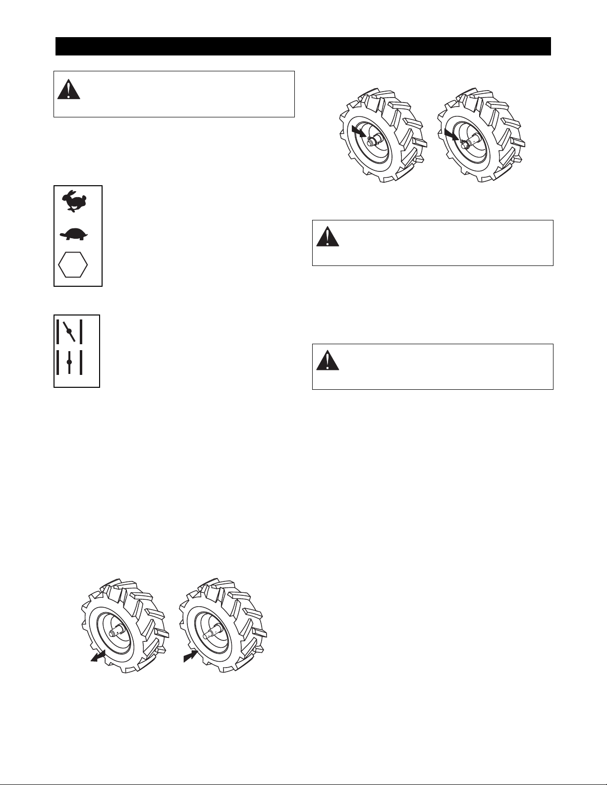
SAFETY ALERTS
Look for these symbols to point out
important safety precautions. They mean:
Attention!
Personal Safety Is Involved!
Become Alert!
Obey The Message!
The safety alert symbols above and signal words below
are used on decals and in this manual.
Read and understand all safety messages.
NOTATIONS
NOTE:
General reference information for proper
operation and maintenance practices.
IMPORTANT:
Specific procedures or information
required to prevent damage to unit or attachment.
PRACTICES AND LAWS
Practice usual and customary safe working
precautions, for the benefit of yourself and others.
Understand and follow all safety messages. Be alert to
unsafe conditions and the possibility of minor,
moderate, or serious injury or death. Learn applicable
rules and laws in your area. Always follow the practices
set forth in this manual.
REQUIRED OPERATOR TRAINING
Original purchaser of this unit was instructed by the
seller on safe and proper operation by the seller. If unit
is to be used by someone other than original
purchaser; loaned, rented or sold, ALWAYS provide
this manual and any needed safety training before
operation.
SAFETY DECALS AND LOCATIONS
ALWAYS replace missing or damaged Safety Decals.
Refer to figure below for Safety Decal locations.
1.
WARNING!
Before operating unit, completely read and
understand all manuals provided.
Keep all safety devices and shields in place.
Never allow children or uninstructed adults to
operate machine.
Stop engine and remove spark plug wire
before clearing tines or repairing.
Keep children and others away from unit while
operating.
SAFETY
DANGER:
IMMINENTLY HAZARDOUS
SITUATION! If not avoided, WILL RESULT in
death or serious injury.
WARNING:
POTENTIALLY HAZARDOUS
SITUATION! If not avoided, COULD RESULT
in death or serious injury.
CAUTION:
POTENTIALLY HAZARDOUS
SITUATION! If not avoided, MAY RESULT in
minor or moderate injury. It may also be used
to alert against unsafe practices.
CAUTION
PRUDENCE
080831
When starting engine
•Make sure clutch is in neutral and
axle drive pins are engaged in wheel
hubs.
•Place feet firmly on the ground and
keep free hand clear of machine.
En démarrant le moteur
•S'assurer que l'embrayage est libre
et que les goupilles d'entraînement
de l'essieu sont engagées dans les
moyeux des roues.
•Se mettre en position stable et dégager
la main de libre de la machine.
CUIDADO
Al arrancar el motor
•Asegúrese que el embrague estéen
neutro y que los dedos de arrastre
del eje impulsor estén enganchados
a los bujes de la rueda.
•Coloque los pies firmemente sobre el
suelo y mantenga su mano libre
alejada de la máquina.
CAUTION
PRUDENCE
CUIDADO
Drive system may
be hot.
080830
Le système
d'entraînement peut
être chaud.
El sistema conductor
puede estar caliente.
077541
DANGER
ROTATING TINES
• Keep hands and feet away.
• Disengage clutch, stop engine and
remove spark plug wire before
clearing.
ROTATION DES DENTS
• Éloigner les mains et les pieds.
• Débrayer, arrêter le moteur et retirer le
câble de la bougie avant dégagement.
ROTACIÓN DE LOS DIENTES
• Mantenga las manos y los pies alejados.
• Desenganche el embrague, pare el motor
y retire el alambre de la bujía de encendido
antes de limpiarlos.
PELIGRO
DANGER
TO AVOID SERIOUS INJURY
• Before operating unit, completely read
and understand all manuals provided.
• Keep all safety devices and shields in
place.
• Never allow children or uninstructed
adults to operate machine.
• Stop engine and remove spark plug
wire before clearing tines or repairing.
• Keep children and others away from
unit while operating.
• Use extreme caution when reversing or
pulling tiller toward you.
• Know location and function of all
controls.
• Do not operate tines with wheel hub
drive pins disengaged. Loss of control
may result.
• Stop engine when travelling between
work areas.
WARNING
POUR ÉVITER LES BLESSURES GRAVES
• Avant de mettre l'appareil en marche, lire entièrement
et bien comprendre tous les manuels fournis.
• S’assurer que tous les garants et autres dispositifs
de sécurité sont en place et fonctionnent correctement.
• Ne jamais autoriser des enfants ou des adultes non
conpétents à utiliser la machine.
• Arrêter le moteur et retirer le câble de la bougie avant
de dégager les dents ou avant réparation.
• Éloigner les enfants et toute autre personne pendant
le fonctionnement de la machine.
• Êrte extrêmement prudent en faisant marche arrière
ou en tirant la machine vers soi.
• Se familiariser avel l’émplacement et la fonction de
toutes les commandes.
• Ne pas faire fonctionner les dents avec les goupilles
activant le moyeu des roues non engagées, ceci
pourrait entraîner une perte de contrôle.
• Arrêter le moteur pendant le déplacement d'un point
de travail à l'autre.
PARA EVITAR LESIONES GRAVES
• Antes de operar la unidad, lea y comprenda
totalmente todos los manuales provistos.
• Mantener todos los dispositivos de securidad y
protectores colocados y funcionando
correctamente.
• No permitir nunca que niños o personas ajenas
operen la máquina.
• Pare el motor y retire el alambre de la bujía de
encendido antes de limpiar o reparar los dientes.
• Mantenga la unidad alejada de los niños u otras
personas cuando esté en funcionamiento.
• Usar precaución extrema al tirar de o empujar la
máquina.
• Conocer la ubicación y función de todos los
controles.
• No opere los dientes del motocultor con los dedos
de arrastre del buje de la rueda desenganchados.
Esto puede resultar en una pérdida de control.
• Pare el motor al desplazarse entre áreas de trabajo.
ADVERTENCIA
080833
AVERTISSEMENT
1
2
3
4
OB0721
Figure 3
OL1801
OL4630
OL4640
OL4650
OL4370

GB - 5
Use extreme caution when reversing or pulling
tiller towards you.
•Know location and function of all controls.
•Do not operate tines with wheel hub drive pins
disengaged. Loss of control may result.
•Stop engine when traveling between work areas.
DANGER! ROTATING TINES
Keep hands and feet away.
•Disengage clutch, stop engine and remove spark
plug wire before clearing.
2. CAUTION!
When starting engine:
•Make sure clutch is in neutral and axle drive pins
are engaged in wheel hubs.
•Place feet firmly on the ground and keep free
hand clear of machine.
3. CAUTION! Drive system may be hot.
4. HOT SURFACES
Do not touch parts which are hot from
operation. Allow hot parts to cool.
ASSEMBLY SAFETY RULES
Read, understand, and follow all safety practices in
owner/operator Manual and engine manual before
beginning assembly. Failure to follow instructions could
result in personal injury and/or damage to unit.
ALWAYS remove wire from spark plug before
assembly. Unintentional engine start up can cause
death or serious injury.
OPERATIONAL SAFETY RULES
Walk Around Inspection
Complete a walk around inspection to understand:
•Work area •Your unit •All safety decals
Work Area
Keep children and people away. Keep children out of
work area and under watchful care of a responsible
adult.
NEVER allow children to operate or play on or near
unit. Be alert and shut off unit if children enter area.
Keep area of operation clear of all toys, pets, and
debris. Thrown objects can cause injury.
Dust, fog, etc. can reduce vision and cause an
accident. Operate unit only when there is good visibility
and light.
Personal Safety
NEVER operate unit after or during the use of
medication, drugs or alcohol. Safe operation requires
your complete and unimpaired attention at all times.
Wear proper footwear. DO NOT operate unit barefoot
or when wearing open sandals or canvas shoes.
DO NOT wear loose clothing that may get caught in
rotating parts.
ALWAYS keep hands and feet away from all rotating
parts during operation. Rotating parts can cut off body
parts.
DO NOT touch unit parts which might be hot from
operation. Allow parts to cool before attempting to
maintain, adjust or service.
NEVER place your hands or any part of your body or
clothing under or near any moving part while unit is
running.
Fumes from engine exhaust can cause injury or death.
DO NOT run engine in an enclosed area. Always
provide good ventilation.
ALWAYS disengage forward and reverse controls, stop
unit and engine, remove spark plug wire and allow
moving parts to stop before leaving operator’s position.
Operation
Understand:
•How to operate all controls
•The functions of all controls
•How to STOP in an Emergency
Disengage forward and reverse controls and engage
wheel hub drive pins before starting engine.
Disengage wheel hub drive pins only when tiller is
transported or not in use, never when engine is
running.
Exercise caution to avoid slipping or falling.
ALWAYS be aware of traffic when operating near
roadways.
Abnormal vibrations are a warning of trouble. Striking a
foreign object can damage unit. Immediately stop unit
and engine. Wait for all moving parts to stop. Remove
wire from spark plug. Inspect unit and make any
necessary repairs before restart.
DO NOT overload tiller by attempting to till too deep at
too fast a rate.
Only allow responsible adults who are trained and
familiar with the instructions to operate the machine.
DO NOT operate at too fast a rate. DO NOT change
engine governor settings or over-speed engine.
ALWAYS keep protective structures, guards and panels
in good repair, in place and securely fastened.
OL4660
OL4490
OD0061

GB - 6
DO NOT operate in reverse unless absolutely
necessary. Use extreme caution when operating in
reverse.
Stay alert for holes, rocks, roots and hidden hazards in
area of operation.
If loss of control occurs when impacting hard ground or
foreign object, release clutch levers and handlebars
and reestablish control. DO NOT force tines down by
hanging on handlebar.
Hazardous Slopes
Operate across the face of slopes, not up and down.
Keep all movements on the slope
slow
and
gradual.
DO NOT operate on steep slopes.
Transport
Use extra care when loading or unloading unit onto
trailer or truck.
Secure unit chassis to transport vehicle. NEVER
secure from rods or linkages that could be damaged.
DO NOT transport unit while engine is running.
DO NOT transport unit while hub drive pins are
engaged.
Turn fuel shut off valve to off position.
Cleaning
Keep unit free of debris. Clean up oil or fuel spills.
Spark Arrester
This product is equipped with an internal combustion
type engine. DO NOT use unit on or near any
unimproved, forest-covered or brush covered land
unless exhaust system is equipped with a spark
arrester meeting applicable local, state or federal laws.
A spark arrester, if it is used, must be maintained in
effective working order by operator.
FUEL SAFETY RULES
Fuel is highly flammable and its vapors are explosive.
Handle with care. Use an approved fuel container.
NO smoking, NO sparks, NO flames. ALWAYS allow
engine to cool before servicing.
NEVER fill fuel tank when engine is running or hot from
operation.
NEVER fill or drain fuel tank indoors.
Replace fuel cap securely and clean up spilled fuel.
MAINTENANCE AND SERVICE SAFETY
RULES
ALWAYS keep protective structures, guards, and
panels in good repair, in place and securely fastened.
NEVER modify or remove safety devices.
DO NOT change engine governor settings or
over-speed engine.
Fumes from engine exhaust can cause injury or death.
DO NOT run engine in an enclosed area. Always
provide good ventilation.
Keep all hardware properly tightened.
Disengage forward and reverse controls, stop engine,
wait for moving parts to stop and remove wire to spark
plug before attempting to unclog, repair, adjust or
inspect unit.
STORAGE SAFETY RULES
NEVER store unit with fuel in fuel tank inside a building
where any ignition sources are present.
Allow engine to cool completely before storing in
closed area or covering unit.
For extended storage, clean unit thoroughly. See
engine manual for proper storage.
ACCESSORY AND ATTACHMENT SAFETY
RULES
Use only attachments or accessories designed for your
unit.

GB - 7
Tools Required
Tire gauge, adjustable wrench or open-end wrenches:
7/16", 1/2" and 3/4".
PACKAGE CONTENTS
PREPARATION
Install Handlebar
Install Forward Clutch Cable
NOTE:
The forward clutch cable exits right side of belt
guard.
1. Remove nut from cable end and install the cable
into the outside hole of the mounting bracket on
the handlebar.
2. Replace the nut onto the cable end. Do not
tighten until cable adjustments have been made.
3. Slide rubber cap onto threaded rod.
4. Install cable eye to the bail stop bracket with .25"
x .75" bolt, flanged bushing and locknut.
5. Adjust cable. See
Service and Adjustments.
ASSEMBLY
WARNING:
AVOID INJURY. Read and
understand
Assembly Safety Rules
in
Safety
section before attempting to assemble unit.
Hardware
Pack
Literature
Pack
Handlebar
Assembly
Tiller
Assembly
Figure 4 DB0062
2. Position handlebars in a safe, comfortable height.
Insert bolts to hold position.
1. Install handlebars to upper
portion of bracket using .38"
hardware. Do not tighten.
3. Place washers and nuts on bolts
inserted in step 2. Tighten all
hardware.
Low Middle High
OB0900
Figure 5

GB - 8
Install Reverse Clutch Cable
1. Locate the reverse clutch cable installed on the
left side of the sheave housing.
2. Remove the nut from the cable end and install the
cable into the inside hole of the mounting bracket
on the handlebar.
3. Replace the nut onto the cable end. Do not
tighten until cable adjustments have been made.
4. Install the rubber cap.
5. Install the cable eye to the reverse lever.
6. Adjust cable. See
Service and Adjustments.
7. Install a tie strap to secure the both clutch cables
to the handlebar. Use tie strap below mounting
bracket.
Check Tire Pressure
Check tire pressure using a low pressure tire gauge for
accurate reading. For correct pressures, refer to
Specifications
.
Check Engine Oil
Engine is shipped without oil in the engine crankcase.
Fill oil to proper level. Refer to engine manual for
detailed instructions.
Fill Fuel Tank
Refer to engine manual for proper type. Fuel tank
capacity is 3 qts. (2.84L).
Check Lubrication
Check for proper lubrication. Refer to
Maintenance
.
Check Function of all Controls
Ensure unit runs and performs properly. Refer to
Operation
.
Test Operator Presence System
1. Start engine in a flat, open area.
2. Engage forward clutch control.
3. Ensure unit drives forward and tines rotate
forward.
4. Release forward clutch control and ensure wheel
drive and tines come to a complete stop.
5. Engage reverse clutch control.
6. Ensure unit drives backward and tines rotate
backward.
7. Release reverse clutch control and ensure wheel
drive and tines come to a complete stop.
IMPORTANT:
DO NOT operate unit if operator
presence system does not function properly. See
Service and Adjustments
to adjust clutches or see your
dealer.
1. Cable Eye
2. Bolt
3. Rubber Cap
4. Nut
5. Forward Clutch
Cable
6. Flanged Bushing
7. Locknut
8. Mounting Bracket
12
3
Figure 6
4
5
6
7
8
1. Cable Eye
2. Rubber Cap
3. Nut
4. Reverse Clutch Cable
5. Mounting Bracket
6. Tie Strap
Figure 7
1
23
4
5
6
WARNING:
FAILURE OF CONTROLS could
result in death or serious injury.
CAUTION:
DO NOT attempt to start your
engine at this time. Thoroughly read this
manual and engine manual.

GB - 9
CONTROLS AND FEATURES
See Figure on page 2 for all Controls and Features
locations.
Throttle
Throttle controls engine speed and stops
the engine. Set throttle in fast position (1)
when starting. Set throttle to stop position
(3) when stopping.
When first operating tiller, use slow engine
speed (2). After you have become familiar
with unit operation, increase throttle to fast
position (1) for best tilling results.
Choke
1. Choke position: chokes off air to engine
for easier start.
2. Run position: allows for normal
operation.
NOTE:
Gradually open choke after engine
starts.
Recoil Starter Handle
The recoil starter handle is used to start the engine.
Wheel Drive Pins
NOTE:
The solid-axle provides equal power to both
wheels. The wheels hold tiller back while tines are
digging.
With wheel drive disengaged, the tiller may be moved
with engine shut off.
To engage/disengage wheel drive:
1. Shut off engine, remove spark plug wire.
2. Remove drive pin from hole.
3. Pull wheel out to engage wheel drive. Push wheel
in to disengage wheel drive.
4. Insert drive pin. Repeat steps on other side of
unit.
Clutch Controls
NOTE:
Clutch is disengaged when forward and reverse
controls are released.
To engage forward travel and tine rotation, depress
forward control to handlebars.
To engage reverse travel and tine rotation:
1. Lift handlebars to raise tines slightly off the
ground.
2. Pull reverse control up to handlebar.
To stop travel and tine action, release all handles.
Handlebar
Handlebars should be set to a safe, comfortable tilling
height.
To adjust handlebar height, loosen upper bolts on
handlebar bracket. Remove lower hardware on
handlebar bracket.
Align holes and secure with hardware.
OPERATION
WARNING: AVOID INJURY. Read and
understand Operational Safety Rules in
Safety section before operating.
STOP
OB0351
1
2
3
OB0840
1
2
To engage To disengage
OB0812
WARNING: DO NOT engage controls unless
wheel hub drive pins are engaged. Tiller may
run away, propelled by the high speed tines.
CAUTION: Avoid injury to feet. Keep away
from tine hood when tiller is traveling in
reverse.
Engaged Disengaged
OB0813

GB - 10
Depth Control
IMPORTANT: DO NOT overload tiller by attempting to
till too deep at too fast a rate.
NOTE: Tilling depth varies with ground conditions.
GROUND AND TINE SPEED
Tiller comes with forward drive belt in low speed groove
of pulley. Low speed is best for heavy tilling. Move belt
to high speed groove for faster tine and wheel speed
for cultivating or breaking up last bits of soil in final
pass.
See Service and Adjustments to change speed.
TILLING WIDTH
To till the minimum width, remove the two outer tine
sets by removing the four nuts and bolts that hold them
to the tine spool.
FILL FUEL TANK
1. Wipe dust, dirt and debris from around cap.
2. Remove fuel cap.
3. Fill gasoline tank. Refer to engine manual for
correct fuel type.
4. Replace cap and wipe up any spilled fuel.
TO STOP IN AN EMERGENCY
To stop the unit:
1. Release forward and reverse controls to
disengage clutch.
2. Move throttle to the “STOP”position.
TO START AND SHUT OFF ENGINE
Before Each Use
Check each item under Before Each Use in the
Maintenance Schedule.
Starting
NOTE: Try controls without running engine to see how
they work and what they do.
1. Open fuel shut-off valve.
2. Move throttle control to fast position.
3. Place choke lever in middle position in warm
conditions. Place choke lever in choke position for
cold weather conditions.
4. Grasp recoil starter handle and pull rope out
slowly until it pulls harder. Let rope rewind slowly.
5. Pull handle with a rapid continuous full arm
stroke. Let rope rewind slowly. Repeat until
engine starts.
IMPORTANT: DO NOT let starter handle snap against
engine.
CAUTION: Do not adjust tilling depth with
tines rotating. Disengage clutch and shut off
engine before changing tilling depth.
OB0781
Figure 9
To change tilling
depth:
1. Remove hairpin
and cotter pin.
2. Reposition depth
control stick.
3. Replace cotter pin
and hairpin.
Till
Deep
Till
Shallow
WARNING: Gasoline is highly flammable and
must be handled with care. Never fill tank
when the engine is running or hot from
operation. DO NOT allow open flame,
matches or smoking in area. DO NOT overfill.
Wipe up any spills. Use approved (Red)
gasoline container.
CAUTION: DO NOT attempt to start your
engine at this time. Thoroughly read this
manual and engine manual.
WARNING: Disengage clutch and place
wheel drive pins in engaged position before
starting engine.
CAUTION: Avoid injury. Do not place hand on
engine exhaust while pulling recoil handle.

GB - 11
Shut Off
1. Release forward and reverse controls to
disengage clutch.
2. Move throttle to the “STOP”position.
TO OPERATE UNIT
1. Set depth stick to desired depth.
NOTE: In previously untilled ground, set depth stick in
second notch from top to a tilling depth of 1/2" to 1"
(11mm to 26mm).
2. Disengage wheel drive.
3. Move tiller to work area.
4. Engage wheel drive.
5. Start engine.
6. Check operator presence system. See Assembly.
7. Practice operating controls and tiller with tines out
of ground before starting to till.
8. Use clutches to till forward and backward.
IMPORTANT:
•Never attempt to engage both forward and
reverse controls at the same time.
•Do not exert pressure on handlebars while tilling.
Heavy pressure on handlebars cause tines to
propel tiller forward instead of digging. Keep both
hands on handle grips when tilling to maintain
balance and direction of tiller.
•If loss of control occurs because of the tines
impacting hard ground or hidden objects, do not
attempt to force the tines down. If control is lost,
release handlebars to stop tines.
•Do not let material build up on tines. Reverse tiller
to unwind debris.
When reaching end of a row, lift handlebars to raise
tines out of ground slightly. Push handlebars to right or
left to turn tiller in desired direction.
NOTE: Tilling wet soil produces hard-to-break lumps.
Tilling soil that is too dry results in powdered soil.
PARKING
To park the unit, release forward and reverse controls
and move the throttle lever to stop position.
TO TRANSPORT UNIT
To transport unit on a truck or trailer:
1. Disengage clutch and stop engine.
2. Close fuel shut-off valve (see engine manual).
3. Place drive pins in disengaged position.
4. Put unit onto truck or trailer and secure.
IMPORTANT: Do not secure unit to transport vehicle
by cables, shields, or linkages that could be damaged.
WARNING: FAILURE OF OPERATOR
PRESENCE SYSTEM could result in death or
serious injury.

GB - 12
Ariens Dealers will provide any service or adjustments
which may be required to keep your unit operating at
peak efficiency. Should engine service be required,
contact an Ariens dealer or an authorized engine
manufacturer's service center.
SERVICE POSITION
Place unit on a flat level surface. ALWAYS stop engine
and disengage clutches. Assure unit is secure and will
not tip over.
MAINTENANCE SCHEDULE
The chart below shows the recommended
maintenance schedule that should be performed on a
regular basis. More frequent service may be required
due to working conditions (heavy loads, high ambient
temperatures, dusty conditions, or airborne debris).
After first two (2) hours of operation.
IMPORTANT: For all engine maintenance information,
refer to engine manual.
Checking Engine Oil
The engine crankcase oil should be checked daily or
every five (5) hours of operation. Oil level MUST be
maintained in safe operating range at all times or
engine damage will result. See engine manual for
detailed instructions.
Change Engine Oil
IMPORTANT: Change oil after first two (2) hours of
operation. Thereafter change oil every fifty (50) hours
of operation (more often in dusty, dirty conditions). See
engine manual for proper type, viscosity and amount
required.
NOTE: Run engine just before changing oil. Oil flows
more freely and carries away more contamination
when warm.
Check Spark Plug
Check spark plug yearly or every 100 operating hours.
Refer to engine manual for detailed instructions.
Service Air Cleaner
See engine manual for detailed information.
General Lubrication
Lubricate all pivot points with oil every twenty-five (25)
hours.
Check Transmission Oil
IMPORTANT: DO NOT run unit without proper amount
of oil.
Every twenty five (25) hours or each season, check oil
level in the gear boxes. If necessary, add Ariens L-2
Special Gear Lubricant at oil fill port. Check and
replace plug when full.
To check oil level in the gear boxes:
1. Position tiller on a flat level surface.
2. Remove the level check plug. Oil should run out
of or be up to check hole.
MAINTENANCE
WARNING: AVOID INJURY. Read and
understand Maintenance and Service and
Battery Safety Rules in Safety section before
attempting any maintenance.
MAINTENANCE SCHEDULE
Before
Each Use
25 50 100
Before
Storage
Check Engine Oil ••
Change Engine Oil ••
Check Spark Plug •
Service Air Cleaner •
General Lubrication ••
Check Transmission
Oil ••
Check Tire Pressure •
Check Fasteners •
*
*
CAUTION: DO NOT touch engine or tiller
drive parts which are hot from operation. Be
careful handling hot drain oil.

GB - 13
If oil level is low:
1. Clean dirt from fill port area.
2. Be sure gear case is level.
3. Add oil at the oil fill port.
4. Recheck oil level and replace plug.
Check Tire Pressure
Every twenty-five (25) operating hours, check that tire
pressure is at 14 PSI.
Check Fasteners
Every fifty (50) operating hours, check all that all
fasteners are properly tightened and in good condition.
CHANGING DRIVE BELTS
NOTE: The forward and reverse drive belts must each
be partially removed in order to remove either belt.
1. Shut off engine and remove spark plug wire from
spark plug.
2. Remove belt cover hardware and belt cover.
3. Remove right belt finger.
4. Remove the forward belt from the top sheave.
5. Remove the reverse belt from idler.
6. Remove belt from sheaves and pull it down and
out from under unit.
7. Remove the forward belt from the bottom sheave
and pull it down and out from under unit.
8. Bring the new reverse belt from under the unit
and install on the idler and top sheave. Make sure
the belt is installed properly under top belt finger.
9. Install forward belt in fast or slow position (See
Ground and Tine Speed).
10. Install the reverse belt on the bottom sheave.
11. Reinstall right belt finger so it is 1/4" (6mm) from
forward belt.
12. Install belt cover and hardware.
13. Connect the spark plug wire.
OB0820
Level Check Plug
Drain Plugs
Figure 10
Oil Fill Port
OB0530
Figure 11
SERVICE AND ADJUSTMENTS
WARNING: AVOID INJURY. Read and
understand Maintenance and Service and
Battery Safety Rules in Safety section before
attempting any maintenance.
1. Top Belt Finger
2. Reverse Drive Sheave
3. Forward Drive Sheave
4. Reverse Belt
5. Right Belt Finger
6. Reverse Clutching Idler
7. Bottom Sheave
8. Forward Clutching Idler
9. Forward Belt
10.Idler
1
2
4
5
OB0841
7
8
Figure 12
3
6
9
10

GB - 14
GROUND AND TINE SPEED
To change forward speed, drive belt is shifted from one
sheave groove to the other groove. Clutch must be
disengaged to move belts.
To Place Belt on Fast Sheave
1. Stop engine.
2. Disconnect spark plug wire.
3. Remove belt guard.
4. Start belt off bottom sheave in direction of
rotation.
5. Pull starter rope slowly to roll belt off sheave.
6. Place belt in fast position on forward and bottom
drive sheaves.
7. Install belt guard.
8. Connect spark plug wire.
To Place Belt on Slow Sheave
1. Stop engine.
2. Disconnect spark plug wire.
3. Remove belt guard.
4. Start belt off drive sheave in direction of rotation.
5. Pull starter rope slowly to roll belt off sheave.
6. Place belt in slow position on forward drive
sheave.
7. Place belt in slow position on bottom sheave.
8. Install belt guard.
9. Connect spark plug wire.
ADJUSTING CLUTCH CABLES
To check forward or reverse clutch cables:
1. Shut off engine, allow muffler to cool and remove
spark plug wire from spark plug.
2. Engage the forward or reverse handle fully and
check the distance the spring extends at the
lower end of the cable. If spring does not extend
from 1/2" to 5/8" (12.7mm to 15.9mm), adjust
cables.
To increase spring length:
1. Loosen adjustment nut toward rubber cap on
clutch cable.
2. Secure cable to bracket by tightening jam nut.
3. Remeasure spring extension distance and
readjust as needed.
To decrease spring length:
1. Loosen jam nut downward on clutch cable.
2. Secure cable to bracket by tightening adjustment
nut.
3. Remeasure spring extension distance and
readjust as needed.
WARNING: DO NOT remove belt cover while
engine is running. Disengage clutch, stop
engine and remove wire from spark plug
before attempting to change belt speed.
CAUTION: Engine and drive parts are hot
after operation.
Forward Belt in Forward Belt in
OB0890
Slow Position Fast Position
Figure 13
1
2
1
2
1. Adjustment Nut
2. Jam Nut
Forward
Cable
Reverse
Cable
Figure 14 OB0830

GB - 15
Check each item in Before Storage in the Maintenance
Schedule. See Engine Manual for detailed instructions
on preparing the engine for storage.
Unit
Store unit in a cool dry protected place.
Inspect unit for visible signs of wear or damage. Order
any parts required and make necessary repairs to
avoid delays when beginning use again.
Clean unit thoroughly.
IMPORTANT: NEVER spray unit with water or store
unit outdoors.
Touch up any chipped or scratched painted areas to
avoid rust.
Engine
When storing tiller for an extended period, refer to
Engine Manual.
STORAGE
WARNING: AVOID INJURY. Read and
understand Storage Safety Rules in Safety
section before operating.
TROUBLESHOOTING
PROBLEM PROBABLE CAUSE CORRECTION
Engine will not
start. 1. Fuel tank empty.
2. Fuel shut off valve in closed position.
3. Engine problem.
1. Fill fuel tank with clean, fresh gasoline. See
Engine Manual for proper type and grade.
2. Place fuel shut off valve in open position.
3. See engine manual.
Engine runs
roughly. 1. Restricted air cleaner.
2. Restricted fuel cap vent.
3. Engine trouble.
1. See engine manual.
2. See engine manual.
3. See engine manual.
Unit does not till in
forward/reverse. 1. Clutch cables need adjustment.
2. Attachment jammed or damaged.
1. Adjust clutch cables. See Service and
Adjustments.
2. Stop engine and remove spark plug wire.
Clear obstruction or repair unit before
operation.
Tines operate
slowly. 1. Clutch needs adjustment or repair.
2. Tines damaged.
3. Engine problems.
1. Adjust clutch cables. See Service and
Adjustments.
2. Repair or replace before operation.
3. See engine manual.

GB - 16
To obtain a complete parts manual, find your model
and serial number. Then go to www.ariens.com or call
1-800-678-5443.
SPECIFICATIONS
Model Number 901026
Description RT7018
Number of Tines 16
Tine Diameter - in. (cm) 12 (30.5)
Adjustable Tilling Width - in. (cm) 9 - 16 (22.9 - 40.6)
Max. Tilling Depth - in. (cm) 6 (15.3)
Height - in. (cm) 42 (106.7)
Length - in. (cm) 58 (147.3)
Width - in. (cm) 22 (55.9)
Weight - lbs (Kg) 180 (81.7)
Tine Speed - RPM 170 - 220
Forward - MPH (KPH) .75 (1.2) - 1.05 (1.6)
Reverse - MPH (KPH) 1.00 (1.5)
Engine Manufacturer Briggs & Stratton
Engine Power - HP (KW) - 4 cycle 7 (5.3)
Engine Governed Speed - RPM 3600 ± 100
Fuel See Engine Manual
for type and grade
Fuel Tank Capacity - qt (L) 3 (2.85)
Air Cleaner Dual Element
Transmission Case Oil Ariens L-2 special
gear lubricant
Crankcase Capacity 20 oz.
Engine Oil Type See engine manual.
Spark Plug Gap 0.030 in. (0.76 mm)
Tire Size - in. (cm) 13 x 5.00-6
(33 x 12.7-15.2)
Tire Air Pressure 14 PSI (.98 k/cm2)
SERVICE PARTS
Order these parts through your dealer.
Part No. Part Description
07202400 Forward V-belt
07238000 Reverse V-belt

GB - 17
2 Year Limited Warranty
Ariens Company warrants to the original purchaser that consumer products manufactured
by Ariens Company will be free from defects in material and workmanship for a period
of two (2) years after the date of purchase, and will repair any defect in material or
workmanship, and repair or replace any defective part, subject to the conditions, limitations
and exclusions set forth herein.
The two year duration of this warranty applies only if the product is put to ordinary,
reasonable, and usual personal, family, or household uses. If the product is put to any
business, commercial, or industrial use such as, but not limited to, commercial landscaping,
mowing or snow removal services, or golf course or park maintenance, or agricultural
or farmstead use, then the duration of this warranty is ninety (90) days after the date
of purchase, or one (1) year after the date of purchase if the product is labeled as a
Professional/Commercial Product. If any product is rented or leased, then the duration
of this warranty is ninety (90) days after the date of purchase.
Genuine Ariens service parts and accessories not purchased with the product covered
by this warranty, but which are later purchased and used with that product, are warranted
to be free from defects in material and workmanship for a period of ninety (90) days
after date of purchase, and Ariens Company will repair or replace any such part or
accessory free of charge, except for labor, during that period.
Ariens Company
655 West Ryan Street
P.O. Box 157
Brillion, WI 54110-0157
920-756-2141
Fax 920-756-2407
www.ariens.com
This warranty is subject to the following conditions, limitations, and exclusions:
This warranty is valid only if the following conditions are
met:
•The warranty registration card must be completed and
returned to Ariens Company.
•The purchaser must perform maintenance and minor
adjustments explained in the owner’s manual.
•The purchaser must promptly notify Ariens Company or an
authorized Ariens service representative of the need for
warranty service.
This warranty is subject to the following limitations:
•The purchaser must transport the product to and from the
place of warranty service.
•Warranty service must be performed by an authorized Ariens
service representative. (To find an authorized Ariens service
representative, contact Ariens Company at the number or
address above.)
•Batteries are warranted only for a period of twelve (12)
months after date of purchase, on a prorated basis. For the
first ninety (90) days of the warranty period, a defective
battery will be replaced free of charge. If the applicable
warranty period is more than 90 days, Ariens Company will
cover the prorated cost of any defective battery, for up to
twelve(12) months after the date of purchase.
The following items are not covered by this warranty:
•Engines and engine accessories are covered only by the
warranty made by the engine manufacturer, and are not
covered by this warranty.
•If the product is equipped with a Peerless gearbox and/or
transmission, the gearbox and/or transmission are covered
only by the warranty made by Peerless, and are not covered
by this warranty.
•Parts that are not genuine Ariens service parts are not
covered by this warranty.
•Shoes, runners, scraper blades, shear bolts, string trimmer
height guide, mower blades, mower vanes, trimmer line,
headlights, light bulbs, are not covered by this warranty.
•Any defect which is the result of misuse, alteration, improper
assembly, improper adjustment, neglect, or accident, is not
covered by this warranty.
•Products which were not purchased in the United States,
Puerto Rico, or Canada are not covered by this warranty. In
all other countries, contact place of purchase.
Form: ALW2-110600
DISCLAIMER OF FURTHER WARRANTY
Ariens Company makes no warranty, express
or implied, other than what is expressly made
in this warranty. If the law of your state provides
that an implied warranty of merchantability, or
an implied warranty of fitness for particular
purpose, or any other implied warranty, applies
to Ariens Company, then any such implied
warranty is limited to the duration of this
warranty. Some states do not allow limitations
on how long an implied warranty lasts, so the
above limitation may not apply to you.
LIMITATION OF REMEDY AND DAMAGES
Ariens Company’s liability under this warranty, and under any
implied warranty that may exist, is limited to repair of any
defect in workmanship, and repair or replacement of any
defective part. Ariens Company shall not be liable for incidental,
special, or consequential damages (including lost profits).
Some states do not allow the exclusion of incidental or
consequential damages, so the above limitation or exclusion
may not apply to you.
This warranty gives you specific legal rights, and you may also have other rights
which vary from state to state.

Ariens Company
655 West Ryan Street
P.O. Box 157
Brillion, WI 54110-0157
920-756-2141
Fax 920-756-2407
www.ariens.com
This manual suits for next models
1
Table of contents
Other Ariens Tiller manuals