manuals.online logo
Brands
  1. Home
  2. •
  3. Brands
  4. •
  5. Ariens
  6. •
  7. Tractor
  8. •
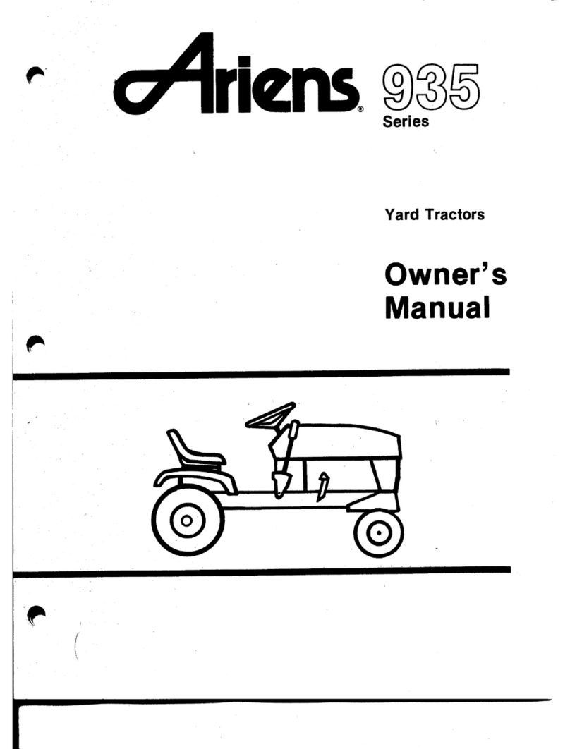
  9. Ariens 935000 Series User manual

Ariens 935000 Series User manual

r
935000 Series
Yard Tractors
Modal 935006 (YT1132) 11 H.P.
Gear drive with 32” mower
Serial no. 003501 and up
Model 935009 (YT1138) 11 H.P.
Gear drive with 38” mower
Serial no. 000101 and up
Model 935011 (YT1032) 10 H.P.
Gear drive with 32” mower
Serial no. 000101 and up
INSTRUCTIONS FOR SAFE OPERATION
1. Know the controls and how to stop quickly. REAO THE
OWNER’S MANUAL.
2. Do not allow children to operate the vehicle. Do not allow
adults to operate it without proper instruction.
3. Do not carry passengers. Keep children and pets asafe
distance away.
4. Clear the work area of objects which might be picked up
and thrown.
5. Sit on seat, disengage traction and attachment power and
shift into neutral before attempting to start the engine.
6. Disengage power to attachment, stop the engine and place
Speed Selector Lever to “NEUTRAL” position and set
parking brake lock before leaving the operator’s position.
7. Disengage power to attachment and stop the engine before
making any repairs or adjustments.
8. Disengage power to attachment when transporting or not
in use.
9. Take all possible precautions when leaving the vehicle
unattended, such as disengaging the attachment power,
lowering the attachment brake lock, stopping the engine
and removing the key.
10. Do not stop or start suddenly when going uphill or
downhill. Operate up and down the face of steep slopes;
never across the face. If you cannot back up the hill, DO
NOT operate the tractor on it. It is too steep for safe opera-
tion.
11.Reduce speed on slopes and in sharp turns to prevent
tipping or loss of control. Exercise extreme caution when
changing direction on slopes.
12. Stay alert for holes in the terrain and other hidden
hazards.
13. Use care when pulling loads or using heavy equipment.
a. Use only approved hitch points.
b. Limit loads to those you can safely control.
c. Do not turn sharpely. Use care when backing up.
d. Use counterweight when suggested in the tractor
owner’s manual or in the attachment owner’s manual. „
14. Watch out for traffic when crossing or near roadways.
15. When using any attachments, never direct discharge of
material toward bystanders nor allow anyone near the
vehicle while in operation.
16. Handle gasoline with care —it is highly flammable.
a. Use approved gasoline container.
b. Never remove the cap of the fuel tank or add gasoline to
arunning or hot engine, or fill the fuel tank indoors.
Wipe up spilled gasoline.
17. Never store the equipment with gasoline in the tank inside
abuilding where fumes may reach an open flame or spark.
Allow the engine to cool before storing in any enclosure.
18. Exhaust fumes are dangerous. Do not run the engine
indoors.
19. Keep the vehicle and attachments in good operating condi-
tion, and keep safety devices in place.
20. Keep all nuts, bolts, and screws tight to be sure the equip-
ment is in safe working condition.
21. To reduce fire hazard, keep the engine free of grass,
leaves, or excessive grease.
22. The vehicle and attachments should be stopped and in-
spected for damage after striking aforeign object, and the
damage should be repaired before restarting and operating
the equipment, see items 6&7.
23. Do not change the engine governor settings or overspeed
the engine.
24. When using the vehicle with mower, proceed as follows:
a. Mow only in daylight or in good artificial light.
b. Shut the engine off when unclogging chute.
c. Check the blade mounting bolts for proper tightness at
frequent intervals.
d. Always look behind you before backing up.
THIS SAFETY ALERT SYMBOL IDENTIFIES IMPORTANT SAFETY INFORMA-
TION IN THIS MANUAL. WHEN YOU SEE THE SYMBOL BE ALERT TO THE
POSSIBILITY OF INJURY AND CAREFULLY READ THE INFORMATION THAT
FOLLOWS.
-2-
CONTENTS
Be Aware of Safety Decals 3
Controls 4.5
Operation 5-6
Adjustments/Maintenance 7-14
Lubrication 14-15
Storage 15-16
Basic Consumer-User Service Components 17-18
Assembly &Pre-Service 19
Registration &Delivery 20
•Road operators manual
•Keep shields in place
•Keep people and pets asate
distance away
•Release parking brake
•Depress clutch pedal
•Shift to desired speed
•Slowly release clutch
ROTATING PARTS
•Keep hands and feet away from under
entire housing
•Oo not operate mower unless grass
catcher is attached or mower guard
is in operating position
32” ONLY
CAUTION
Before startmy engine be sure
machine is in neutral and
implement clutch is disemjatjed *
ROTATING PARTS
•Keep hands and feet
away from under
entire housing
•Do not operate mower
unless grass catcher is
attached or mower guard
is in operating position
FEATURES AND CONTROLS
®IGNITION AND STARTER SWITCH —FIGURE 1
The ignition and starter switch has three positions: “OFF",
“RUN", and “START”. Start the engine by turning the key
fully clockwise to “START" position and then release the key as
soon as the engine starts. Stop the engine by turning the key
counterclockwise to the “OFF" position.
®THROTTLE-CHOKE CONTROL LEVER —FIGURE 1
This control operates both the throttle and choke. When starting
acold engine, raise the lever past the offset and into the
"CHOKE” position. After the engine has started, lower the lever
to the throttle operating range and allow the engine to warm at
1/2 throttle. Select the appropriate engine speed in the throttle
range after the engine has warmed up.
NOTE: UNLESS OTHERWISE SPECIFIED, THE ATTACHMENTS
SHOULD BE OPERATED AT FULL THROTTLE. THE THROTTLE IS
NOT TO BE USED TO SELECT DESIRED TRAVEL SPEEDS.
OPERATE AT FULL THROTTLE AND REGULATE GROUND SPEED
WITH THE GEAR SHIFT LEVER.
©LIGHT SWITCH —FIGURE 1
Turn lights on by pulling the control knob out. Turn lights off by
pushing the knob in.
@ATTACHMENT LIFT LEVER —FIGURE 1
To raise the attachment, depress thumb button, pull the lever to
the rear, and release thumb button. This will hold the attachment
in the raised position. When using the mower attachment, select
the “notch" that allows the mower to cut at the desired height.
To lower the attachment, pull the lever to the rear, depress the
button to release the latch and allow the lever to move forward.
©IMPLEMENT POWER CONTROL —FIGURE 1
The Implement Power Control is used to operate the at-
tachments. Push the lever forward to engage the clutch and
drive the attachment. Pull the lever rearward to disengage the
clutch and stop the attachment. The lever must be in the rear
(disengaged) position to start the engine. THIS IS ASAFETY
FEATURE. The engine will not start until the lever has been
placed in the disengaged position.
©SPEED SELECTOR LEVER -FIGURE 2
The Speed Selector Lever is used to select any of three forward
gears or one reverse gear. The markings “1, 2, 3“ and "R” on
the floor plate indicate the locations of the gears. The slowest
forward gear is indicated by “1 ", the secondary gear, "2", and
the fastest gear, "3”. The "R" indicates reverse. The Speed
Selector Lever must be in the “NEUTRAL" position as shown in
Figure 2to start the engine. THIS IS ASAFETY FEATURE.
©HIGH-LOW SPEED RANGE SELECTOR -FIGURE 2
The High-Low Speed Selector gives achoice of six forward
speeds; three in “HIGH" range; and three in “LOW" range.
The speed in reverse gear is the same in both ranges.
FIGURE 2
©CLUTCH PEDAL -FIGURE 1
Depressing the Clutch pedal disengages the transaxle from the
engine and permits shifting the speed selector to any desired
gear. Always release the clutch pedal slowly' for smooth ac-
celeration. Do not allow foot to rest on pedal except when
clutching.
IMPORTANT: ALWAYS DEPRESS CLUTCH PEDAL TO EASE
ENGINE STARTING. DEPRESSING CLUTCH PEDAL RELEASES
PARKING BRAKE. BE READY TO APPLY FOOT BRAKE WHEN
STARTING FROM PARK POSITION.
©BRAKE PEDAL —FIGURE 1
Depressing the brake pedal applies pressure to the disk brake
and stops the tractor (with the clutch depressed). Be sure to
depress clutch pedal to disengage the clutch before braking.
Brake will not stop tractor without depressing clutch pedal.
©PARKING BRAKE LOCK -FIGURE 3
AParking Brake Lock is provided to prevent the tractor from
moving when parked or left unattended. To lock the brake, pull
the parking brake lock up with the pedal fully depressed. Then
release the brake pedal. Figure 3shows the parking brake lock
engaged. Clutch pedal must not be depressed when locking
brake. Parking brake lock may be disengaged by depressing
either brake or clutch pedal.
-4-

1FEATURES AND CONTROLS
AA
IMPORTANT: ENGAGE THE 8RAKE LOCK BEFORE DISMOUN-
TING FROM THE TRACTOR OR ANY TIME IT IS LEFT UNAT-
TENDED.
CAUTION. WHEN USING TRACTOR 0R ATTACHMENT FOR THE
FIRST TIME USE LOW RANGE SPEEDS AND LOWER GEARS TO
MAKE SURE OF YOUR CONTROLS
1OPERATION
WHEN USING ATTACHMENTS OTHER THAN MOWERS
Arear weight box and wheel weights are available to increase
traction when using the Sno-Thro or the front blade attachments.
Rear tire chains are also available for use in snow conditions
NOTE: TOO MUCH REAR WHEEL TRACTION WILL RESULT IN
DRIVE TRAIN 0VERL0A0 AND POSSIBLE DAMAGE.
THEREFORE: WEIGHT BOX LIMIT IS 125 LBS. REAR TIRE
CHAINS ARE NOT TO BE USED ON DRY SOIL OR GRAVEL.
PRE-STARTING INSPECTION
1.Check oil in engine crankcase. Add oil as required to main-
tain proper level See "LUBRICATION” section.
2. Check fuel supply. Fill with clean, fresh gasoline only. See
Engine Instructions manual provided for fuel recommenda-
tion.
3. Check air cleaner and tire pressures.
4. Check for engine, transmission or differential oil leaks.
See your Ariens dealer for repairs.
5. Make visual checks regarding safety precautions,
obstructions and maintenance.
STARTING THE ENGINE
Use the following procedure to start the engine.
1Depress Clutch Pedal ©and hold the tractor in position by
depressing the Brake pedal Q.See Figure 1
.
2Place the Speed Selector Lever ©in the "NEUTRAL”
position as shown in Figure 2.
NOTE: THE ENGINE WILL NOT START UNLESS THE SPEED
SELECTOR LEVER IS IN THE "NEUTRAL” POSITION.
3Place Implement Power Control ©Figure 1, in the rear
(disengaged) position
NOTE THIS IS ASAFETY FEATURE. THE ENGINE WILL NOT
START UNLESS THE IMPLEMENT POWER CONTROL IS IN THE
DISENGAGED POSITION
4. Raise Throttle-Choke Control Lever ©Figure 1. past the
offset in the slot to the "CHOKE” position
NOTE: OPERATOR MUST BE ON SEAT TO START UNIT TRAC-
TOR HAS ASEAT SWITCH FOR SAFETY.
5. Turn ignition key ©shown in Figure 1clockwise all the
way. Release key as soon as the engine starts and
gradually lower the Throttle Choke Control Lever past the
offset until the engine runs at '/? throttle.
NOTE: AWARM ENGINE WILL REQUIRE LESS CHOKING THAN A
COLD ENGINE.
If the engine fails to start on the first attempt, turn key to the
"OFF” position, wait afew minutes and try again. Do not
operate starter continuously for more than 30 seconds at atime.
Always allow engine to warm up before applying load. In below
freezing weather, allow engine to run at afast idle for aperiod of
at least five minutes before moving the tractor or starting the at-
tachment. SERIOUS DAMAGE TO THE ENGINE AND TRANSMIS-
SION COULD RESULT IF THIS PROCEDURE IS NOT FOLLOWED.
STOPPING THE ENGINE
Always use the following procedure to stop the engine:
1. Move the Speed Selector Lever ©(Figure 1) to the
“NEUTRAL” position.
2. Disengage the Implement Power Control ©.Figure 1.
3. Engage Parking Brake Lock ©by depressing the Brake
Pedal ©(Figure 1) and pulling up on the Parking Brake
Lock ©(Figure 3).
-5-
STOPPING THE ENGINE (CONTINUED)
4. Lower attachment to the ground.
5. Lower Throttle Choke Control Lever and allow the engine to
idle for ashort period of time. DO NOT STOP AHOT
ENGINE AT HIGH SPEED AS INTERNAL ENGINE DAMAGE
COULD RESULT.
6. Turn ignition key counterclockwise to the “OFF" position
to stop the engine.
SELECTOR LEVER WHILE RELEASING THE CLUTCH PEDAL. THE
CLUTCH PEDAL MUST BE DEPRESSED TO ENGAGE ANY
SELECTED GEAR. DEPRESSING THE PEDAL TOO LITTLE WILL
CAUSE GEAR CLASH AND POSSIBLE DAMAGE TO THE
TRANSMISSION. HOLD LEVER TOWARD -ENGAGED POSITION
WHILE DECLUTCHING. A
WARNING:
7.
BE CAREFUL: REMOVE IGNITION KEY BEFORE DISMOUN- 1BEFORE SERVICING ANY ATTACHMENT-
TING FROM TRACTOR. THIS WILL PREVENT CHILDREN
AND INEXPERIENCED OPERATORS FROM STARTING THE aDISENGAGE POWER TO ATTACHMENT
TRACTOR.
OPERATING THE TRACTOR b. SHUT OFF ENGINE.
1.
Start the engine using the procedure explained under
“Pre-starting Inspection” and “Starting the Engine".
NOTE: THE SPEED SELECTOR LEVER MUST BE IN THE
NEUTRAL POSITION, THE IMPLEMENT POWER CONTROL
DISENGAGED AND THE OPERATOR ON SEAT TO START THE
ENGINE.
c. MAKE SURE ATTACHMENT HAS STOPPED REVOLV-
ING.
d. DISCONNECT ENGINE SPARK PLUG CABLE TO PRE-
VENT ACCIDENTAL RESTART.
2.
KEEP CHILDREN, BYSTANDERS, AND PETS OUT OF THE
WORKING AREA.
2. Release Parking Brake Lock ©by depressing the Brake
©or Clutch Pedal ©(Figure 1) until the lock disengages.
3. Depress Clutch Pedal, place Speed Selector Lever ©and
High-Low Range Selector ®(Figure 1) into the desired
gear and range and slowly release the pedal to provide
smooth acceleration.
4. Select the desired throttle speed with the Throttle-Choke
Control Lever. When operating apower-driven attachment,
operate the engine at full throttle, (3250 RPM) unless
otherwise specified and control travel speed by selecting
an appropriate gear.
5. To raise or lower the attachment use the Attachment Lift
Lever ©.
6. To start the attachment, engage the Implement Power Con-
trol ©slowly with the engine running at Vt throttle, then
increase speed to full throttle.
7. To stop the tractor, fully depress Clutch and Brake Pedals
and place Speed Selector Lever in “NEUTRAL”. Fully
depress Brake Pedal and engage the Parking Brake Lock
when parking or leaving the tractor. (Figures 1, 2&3)
EMERGENCY STOPPING
Always use caution when mowing-be alert for children, pets or
obstacles in path. If necessary to make emergency stop, firmly
depress Clutch Pedal and Brake Pedal.
3. KEEP HANDS, FEET AND CLOTHING AWAY FROM POWER
DRIVEN PARTS.
4. KEEP ALL SHIELDS AND GUARDS IN PLACE.
OPERATING TIPS
NOTE: FOR BEST CUTTING RESULTS CLEAN INSIDE OF MOWER
PAN AFTER EACH MOWING OPERATION IS COMPLETED.
NOTE: OPERATE ENGINE AT “FAST” THROTTLE-SETTING AND
SELECT SPEED SELECTOR LEVER AS DESCRIBED IN FOLLOW-
ING INSTRUCTIONS.
1. The Tractor may be operated at one of three forward
speeds or one reverse speed in each of two speed ranges.
Depress Clutch Pedal ©and use Speed Selector
Lever® to shift from “NEUTRAL” (N) to First Speed (1)
or Reverse (R).
2. The operator should acquaint himself with the area to be
mowed and slow down using Speed Selector Lever ©
,
not Clutch, to maintain control in restricted spaces.
IMPORTANT: DO NOT FORCE SPEED SELECTOR LEVER IF GEAR
OOES NOT ENGAGE. APPLY SLIGHT PRESSURE ON THE SPEED
3.
In heavy cutting conditions, where grass may be extremely
high or thick, the Attachment Lift Lever® should be set
at ahigher setting than normal and the Speed Selector
Lever© set at Second or First Speed.
-6-
OPERATION
OPERATING TIPS (CONTINUED)
4. The use of higher Lever settings will allow grass cutting in
heavy conditions without lugging the engine. Asecond
cutting may be required in some cases to mow grass to the
desired height.
5With aGrass Bagger the use of lower ground speeds may
be required depending on grass conditions. Avoid cutting
at too low aheight which may lug engine and cause plugg-
ing of the discharge area or bagger.
6. Generally, try tractor operation af lower ground speeds un-
til you are familiar with the controls of the unit, then ex-
periment with higher speeds if desired. Be sure that safe
operation is possible at the speed traveled. Avoid cutting
grass when wet.
ADJUSTMENTS/ MAINTENANCE
GENERAL
Aliens Dealers will provide any service which may be required to
keep the Yard Tractor operating at peak efficiency. Ariens Com-
pany recommends that you contact an Ariens Dealer before
making any major adjustments to this tractor. Refer to the Engine
Instructions for engine maintenance instructions. If repairs or
service are required for the engine, see your Ariens Dealer or the
nearest authorized engine service station.
SEAT ADJUSTMENT
The seat is adjustable front or back to many positions. Adjust-
ment is made by loosening the two rear mounting bolts located
under rear of the seat; sliding the seat to the most comfortable
position and then tightening the mounting bolts.
C" RAISING THE HOOD -FIGURE 4
1. The engine, battery, electrical components, air cleaner,
fuel filter and fuel tank are readily accessible by raising the
hood.
2. To raise the hood, grasp each side and raise it upwards
and forward until it stops.
RAISING THE REAR DECK —FIGURE 4
The transaxle, PTO and jackshaft assembly, clutch idler, and
Traction Drive Belt are readily accessible by raising the rear deck
until the seat rests against the steering wheel.
AIR CLEANER SERVICE
Clean the air cleaner and re-oil the element every 25 hours under
normal operating conditions. When operating in extremely dusty
conditions, perform this service at more frequent intervals.
1. Raise the tractor hood for access.
2. Remove ihe air cleaner cover and service per engine
manufacturer's instructions furnished with the tractor.
3. Replace the cover and lower the hood.
IMPORTANT: NEVER RUN THE ENGINE WITH THE AIR CLEANER
REMOVED!
ENGINE COOLING SYSTEM —FIGURE 6
1. The engine is air cooled. Grass particles, chaff and dirt
may clog the cooling system, especially when mowing dry
grass or operating in extremely dusty conditions. Con-
tinued operation with aclogged cooling system may cause
severe overheating and possible engine damage.
ADJUSTMENTS/ MAINTENANCE
ENGINE COOLING SYSTEM (CONTINUED)
2. It is essential that the rotating screen, engine cooling fins
and the exhaust system be kept free of dirt and debris
which could cause the engine to overheat.
3. To avoid overheating and possible engine damage,
periodically remove the shrouding from around the cooling
fins, Figure 6, and clean the area shown within the heavy
black line of all grass, dirt or chaff accumulation.
SEAT MAINTENANCE
When cleaning seat use avinyl cleaner (not asolvent.) Protect
the seat from weather damage by storing tractor inside an
enclosure or by covering the seat. If the seat is damaged repair it
with avinyl repair, kit. A
CAUTION: REMOVE BATTERY FROM TRACTOR BEFORE TIPPING
OR LIFTING THE UNIT FOR ADJUSTMENTS. BATTERY IS NOT
SEALED AND SPILLED ACID WILL DAMAGE EQUIPMENT. WHEN
HANDLING BATTERY BE SURE TO AVOID CONTACT WITH BAT-
TERY ACID, WHICH CAN CAUSE SERIOUS INJURY TO EYES,
ETC.
BATTERY SERVICE A
WARNING: STORAGE BATTERIES GIVE OFF HIGHLY INFLAM-
MABLE HYDROGEN GAS. DO NOT ALLOW SPARKS OR FLAME
NEAR BATTERY. DO NOT LAY TOOLS ACROSS BATTERY TER-
MINALS WHICH MAY CAUSE ASPARK RESULTING IN AN EX-
PLOSION.
BATTERY CHARGE RATE
PRODUCT MODEL FOR 10 HRS. /s
Tractor Ariens 291 75 3.9 Amps
(WISCO LM-9) %
NOTE: CHARGING BATTERY AT AHIGHER RATE WILL DAMAGE
BATTERY.
1. Do an occasional visual inspection. Be sure to keep the '
battery clean, both the case and the terminals. This visual
inspection should be done once amonth.
2. Check the level of the electrolyte. It may be necessary to
add distilled water. This should be checked before each
usage.
3. Another important check is the specific gravity. The
specific gravity should be checked with ahydrometer.
NOTE: AHYDROMETER, PART NO. 140, OFFERED THROUGH
ARIENS IS RECOMMENDED FOR ALL SET-UP AND
MAINTENANCE PROCEDURES OF ARIENS BATTERIES.
TIRE PRESSURES -TABLE 1
Check tires pressures at least once each month. Inflate tires to
pressures shown using alow pressure tire gauge for accurate
readings. Keep tires properly inflated at all times. Over-inflation
will cause operator discomfort. Under-inflation will cause short
tire life. Make sure the tire valve caps are in place. r-
UBESKE
Ujht
kQAPINQ
Httvy
Front
13 x5.00 -6
(Lawn Work)
10 psi
(Tilling)
12 psi
(Sno-Thro)
16 psi
Rear
18x8.50-8
(Lawn Work)
6psi
(Sno-Thro)
8psi
(Tilling)
10 psi
TABLE 1
FUEL FILTER SERVICE —FIGURE 7
When dirt or other foreign material is allowed to enter the fuel
tank it will collect in the fuel filter eventually causing fuel stop-
page. If this occurs, replace filter.
CAUTION: ELECTROLYTE CONTAINS SULPHURIC ACID WHICH
IS HARMFUL TO SKIN. EYES AND CLOTHING. HANDLE WITH
EXTREME CARE. IF SPILLAGE OCCURS ON BODY OR
CLOTHING, RINSE AT ONCE WITH WATER.
WARNING: REVERSED BATTERY CABLES OR REVERSED
CABLES FROM ABATTERY CHARGER OR BOOSTER BATTERY
CAN CAUSE DAMAGE TO THE PRODUCT. SPARKS AND POTEN-
TIAL HAZARDS TO OPERATOR COULO RESULT. MAKE CERTAIN
THE GROUNO CABLE IS CONNECTED TO THE ENGINE AND THE
POSITIVE CABLE IS CONNECTED TO THE POSITIVE (+)TER-
MINAL.
MOWER BLADE AND VANES -FIGURES 8A9
Check tire pressure. Uneven tire pressure may cause uneven
grass cutting.
-8•
ADJUSTMENTS /MAINTENANCE
MOWER BLADE AND VANES (CONTINUED)
Mowers are equipped with high lift blades standard. Vanes may
be bolted to the blades to improve discharge and bagging or col-
lecting of grass. These vanes may or may not be helpful de-
pending on your type of grass and cutting conditions.
Ariens recommends that the user try the mower without vanes
first and if the performance is satisfactory, use without vanes
since the vanes use more power and generate more noise. Use
vanes only if satisfactory performance cannot be obtained
without them. Generally, broadleaf grasses can be cut and bagg-
ed without vanes. The finer grasses may require vanes, in damp
conditions, vanes may also be of help.
Routinely check for wear on the mower blade and vanes, if used.
This is especially true in sandy soil conditions.
A
CAUTION: WEAR OF THE MOWER BLADE CAN CAUSE STRUC-
TURAL WEAKNESS. DO NOT INSTALL NEW OR REPLACEMENT
VANES ON WORN BLADES. THIS IS APOTENTIAL HAZARD.
Replace worn parts with Ariens original equipment, blades,
vanes, and Grade 8hardware as specified. Cap screws must be
installed with heads on top of the vanes and vanes on top of the
blade. See Figure 8.
NOTE: CAP SCREWS MUST BE 6RA0E 8
LOCATED ON TOP OF VANES CAP SCREWS §?
j|
1AS SHOWN. /h
NOTE: MOUNT VANE /
TO BLAOE AS /
SHOWN ONLY
WITH WORD
“FRONT
EXPOSED
r/
|f*U
LOCKNUT
CUTTING —
EDGE
FIGURE 8
IMPORTANT: THE VANES MUST BE USED IN PAIRS. THEY CAN-
NOT BE INTERCHANGED WITH DIFFERENT OR WORN VANES ON
THE SAME BLADE. USING ONE OF EACH OF ADIFFERENT TYPE
OR WORN VANE WILL CAUSE THE BLADE TO BE OUT OF
BALANCE AND SEVERE VIBRATION WILL OCCUR. EVEN WEAR
ON THE PARTS AND PROPER BALANCE IS ENSURED BY
REPLACING VANES IN PAIRS.
The mower blade should always be kept sharp and properly
balanced. Disconnect spark plug wire. Remove Mower Pan,
clear dirt and grass from underside, and check blade. Use a
heavy glove or padding for hand protection while removing
mower blade. Remove the nut and lockwasher securing the
blade and remove blade. See Figure 4.
Replace mower blade in position on mower and secure with
lockwasher and nut. Use aheavy wrench; torque to 50-55 lbs.
Be sure to use aheavy glove or padding for hand protection while
fastening blade. See Figure 9.
SHIFT LEVER DETENT ADJUSTMENT —FIGURE 10
Check tightness of screws holding shift handle in the detent
positions. Screws must be tightened securely. This will eliminate
jumping out of gear. See Figure 10.
DISC BRAKE ADJUSTMENT —FIGURE 11
Once each season, or if the brake begins to slip and does not
hold the tractor, it is necessary to adjust the disc brake located
on the lower left side of the transaxle assembly. See Figure 11
.
Adjust as follows:
1.Position the tractor on asmooth level surface and place the
Speed Selector Lever in "NEUTRAL” so the tractor can be
pushed by hand to check the brake.
FIGURE 11
-9-
ADJUSTMENTS/MAINTENANCE
DISC BRAKE ADJUSTMENT (CONTINUED)
2.
Adjust the setscrew in the brake jaw assembly clockwise
until the brake just starts to lock. This can be felt by
pushing the tractor by hand. Leave the brake pedal up
during this adjustment.
1
.
Lower the Attachment Lift lever. One front set of pins and
washers will connect the tabs on the front of the mower
pan to the front hangers, the second set of pins and
washers connect the front of the pan to the belt tightener
bracket. The rear set of pins and washers connect the rear
hangers to the frame.
3.
Turn setscrew 1/2 turn counterclockwise from locking
point to adjust the brake.
BRAKE PEDAL SPRING ADJUSTMENT —FIGURE 3
The tension on the Brake Pedal itself is adjustable. If the brake
pedal does not return or feels loose, adjust the nut on the end of
the brake rod just inside the frame next to the parking brake slot.
Tighten the nut until the spring adjacent to the nuts is 1V* in-
ches in length.
REMOVAL OF MOWER PAN -FIGURES 12 &14
In order to perform some maintenance it may be necessary to
remove the mower pan as follows:
1. Lower the mower pan. Remove the hairpin cotter and
washer from the stud on the attachment idler (Figure 16)
and disconnect the mower brake link.
2. Raise the mower deck. Loosen the belt fingers on the trac-
tor PTO sheave, slide them to one side, and remove the
mower belt from this sheave. See Figure 16.
3. Lower the mower pan and remove the hairpin cotters and
washer. The two pins and washers on the front secure the
mower pan to the front hangers and can be disconnected
to free the front of the pan. The other two pins and
washers join the front of the pan to the belt tightener
bracket. Loosen the hex nuts and turn the rear hanger
hooks to the side to free them from the rear hangers. See
Figure 12.
4. Place front hanger on top of rear hanger. Raise the Attach-
ment Lift Lever to pull the hangers up out of the way. Pull
the mower pan from under the tractor.
The front and rear hangers may be assembled and engaged with
washers and hairpin cotters.
2. With the Mower Belt in place on the pan and the lift arm in
its highest position, position the pan under the tractor and
forward against the front wheels.
3. Lower the Attachment Lift Lever. Slide the pan back (while
lifting the rear of the pan) so that the pan hanger hooks
slide up on the rear hanger. Assemble the front hangers to
the tabs on the mower pan, while, at the same time,
assembling the front and rear hangers. Secure with four
washers and hairpin cotters. Connect the Belt Tightener
Bracket to the pan.
4. Raise the Attachment Lift Lever to maximum height. Con-
nect Mower Belt to PTO Sheave.
5. Connect the blade brake arm to the stud on the center of
the Attachment Clutch Idler. Secure with awasher and a
hairpin cotter.
6. Adjust the belt fingers on the tractor PTO Sheave to clear
the belt by 1/8 to 1/16”. Tighten the belt finger hard-
ware.
INSTALL BLADE BRAKE ARM AS SHOWN
cjnno 35281 BRACKET
64093 WASHER
67020 HAIRPIN
Y
35235 (32” MOWER)
35248 (38” MOWER)
X'
64093 WASHER
67020 HAIRPIN
FIGURE 13
MOWER PAN LEVELING —FIGURES 12, 14 &18
FIGURE 12
INSTALLATION OF MOWER PAN -FIGURES 12 &13
Position the tractor on asmooth, level surface and install the
mower pan as follows:
The mower pan is designed to cut evenly with the rear of the pan
1/8 inch higher than the front. To level the mower pan proceed
as follows:
1.Position the tractor on asmooth level surface. Adjust tire
pressure as follows (light loading):
Front -10 psi /Rear -6psi
2. Measure the distance from surface to mower blades at the
front and rear of the pan. The rear of blades should be 1/8
inch higher than front and blades should hang even side to
side.
3. If adjustment is required, turn the hex nuts on the rear
hanger hooks to move the hooks up or down to secure the
proper adjustment. When the pan is leveled and hangs
evenly, tighten the hex nuts securely. See Figure 12.
-10 -
ADJUSTMENTS/MAINTENANCE
MOWER PAN LEVELING (CONTINUED)
4.
Adjust Mower Belt for proper center distance. See Figure
14 and 19. Adjust nuts on the adjustor rod to move mower
pan forward or rearward. Adjust for 1to I’/? inch
clearance between belt as shown in Figure 19 with mower
pan in highest position.
A
CAUTION: ADJUSTMENT TOO FAR FORWARD WILL NOT ALLOW
MOWER BELT TO DECLUTCH! CHECK FOR PROPER MOWER
BELT DECLUTCHING IN ALL HEIGHT POSITIONS. IF MOWER
BELT'DOES NOT DECLUTCH. ADJUST MOWER PAN BACKWARD
UNTIL PROPER DECLUTCHING OCCURS. (P.T.O. SHEAVE MUST
NOT HAVE ATENDENCY TO DRIVE MOWER BELT AND/OR
OVERRIDE BRAKE.)
ADJUSTMENT NUTS —
.
MOUNTING POST
\h£ON FRONT AXLE
ADJUSTOR ROD nr -HAIRPIN
BELT TIGHTENER BRACKET
FIGURE 14
MOWER PAN CUTTING HEIGHT —FIGURE IS
After the mower pan has been leveled properly, minor ad-
justments can be made in the pan cutting height by increasing or
decreasing the center distance between 35321 rod end and
35322 adjustment link. Increasing center distance lowers cut-
ting height. Decreasing center distance raises cutting height.
Raising the Attachment Lift Lever to another notch in the iift
quadrant will also raise the cutting height of the mower pan. Ad-
just to suit individual grass cutting conditions.
MAIN DRIVE BELT REPLACEMENT -FIGURES 16 &17
A. Removal of main drive belt.
NOTE: REMOVE SPARK PLUG WIRE.
1
.
Loosen or remove the three fasteners holding spindle
housing and belt fingers on transaxle mount near PTO
sheave and remove or rotate the belt fingers away from
PTO sheave. See Figure 16. Spindle housing should be
free to move, allowing belt removal.
2. Move Implement Clutch Lever to "OUT."
3. Move Attachment Lift Lever to highest position.
4. Unwrap mower drive belt from PTO Sheave (DO NOT
PRY).
5. Move Attachment Lift Lever to lowest position.
6. Move Implement Clutch Lever to "IN."
7. Remove hairpin and mower brake link from attachment
idler. See Figure 16.
8. Disconnect attachment idler spring from anchor on
right side of transaxle. (Use vise grips —See Figure
16.)
9.
Remove cotter pin, washer and PTO Rod from attach-
ment idler arm. See Figure 16.
FIGURE 16
10. Loosen fasteners holding two belt fingers around
traction drive belt to frame, and rotate fingers away
from belt. See Figure 17.
11.Depress Clutch Pedal with left foot and unwrap trac-
tion drive belt from transaxle and upper groove of
top PTO sheave. See Figure 17.
12. Release clutch, disconnect traction clutch spring
from traction clutch idler arm. (Use vise grips). See
Figure 17.
13. Rotate attachment idler until hair pin at top of idler
assembly pivot pin can be removed rearward. See
Figure 17.
-11 -
ADJUSTMENTS/MAINTENANCE
MAIN DRIVE BELT REPLACEMENT (CONTINUED)
14. Remove PTO pivot pin, hairpin and washer. See
Figure 16.
15. Lower attachment idler assembly until traction
clutch idler arm is free of pivot pin.
16. Disconnect main idler spring from anchor point at
left side of frame. (Use vise grips). See Figure 16.
17. Slide rear of belt ahead and between upper traction
and lower attachment idler assemblies. See Figure
16.
18. Unwrap main drive belt from engine sheave and
remove from tractor.
B. Installation of New Belt
1.Wrap new main drive belt around engine sheave.
2. Feed other end rearward, above steering arm and
through, between upper traction and lower attach-
ment idler pivot assemblies.
3. Push attachment idler arm upward until pivot pin is
completely positioned through the traction clutch
idler arm pivot.
4. Rotate attachment idler arm so that hairpin can be
re-installed in a forward direction. Place washer over
pivot pin, install hairpin.
5. Move Implement Clutch to “IN”.
6. Feed PTO rod between main drive belt lengths and
install end through hole in attachment idler arm. See
Figure 16.
7. Install washer and cotter pin in PTO Rod -See Figure
16.
8. Connect attachment idler spring to anchor on right
front corner of transaxle. (Use vise grips.)
9. Wrap main drive belt around lower (larger groove on
top PTO sheave.) See Figure 17.
10. With the main drive belt in the groove, re-assemble
the spindle housing and belt fingers. See Figure 16.
1 1 .Reconnect main idler spring to anchor hole on left
side of frame. Be sure main idler is on backside of
main drive belt and spring is above steering link.
See Figure 16.
12. Grasp traction clutch idler spring with vise grips and
connect hook to traction clutch idler arm. See Figure
17.
13. Depress traction clutch pedal and wrap traction
drive belt around upper groove on PTO sheave and
transaxle sheave. DO NOT PRY. See Figure 17.
14. Release clutch pedal and align and tighten traction
belt fingers to 1/16" to 1/8" from belt.
15. Move Implement Clutch Lever to "OUT" and move
Attachment Lift Lever to highest position.
16. Wrap mower belt around bottom PTO sheave. DO
NOT PRY.
17. Re-align fingers around bottom PTO sheave 1/16"
to 1/8" away from pulley and tighten.
18. Move Implement Clutch Lever to "IN".
19. Attach mower brake link to stud under attachment
idler and secure with hairpin. See Figure 13.
20. NOTE: LEAVE SPARK PLUG WIRE DISCONNECTED.
21 .Move Attachment Lift Lever to lowest position.
22.
Move Implement Clutch Lever to "OUT”. Place
Speed Selector Lever in "NEUTRAL".
FIGURE 17
23. Crank engine (with starter only) about six revolu-
tions.
24. Inspect main drive belt and main idler for alignment
and clearance from sharp edges.
25. Replace spark plug wire and test function.
TRACTION DRIVE BELT REPLACEMENT —FIGURE 17
The traction drive belt is easily replaced by lifting the rear deck;
loosening the belt fingers: including belt finger on traction clutch
idler arm; depressing the Clutch Pedal and removing the belt.
Replacement is similar, depress the Clutch Pedal; install the belt
and replace the belt fingers. Adjust the three belt fingers to pro-
vide 1/8 to 1/16 inch clearance from the belt with clutch engag-
ed (pedal up).
-12 -
ADJUSTMENTS/ MAINTENANCE
MOWER BELT REPLACEMENT &ADJUSTMENT —
FIGURES 18 &19
If belt squeals when Implement Power Control is properly engag-
ed. check adjustment of belt. If squeals continue, belt may re-
quire replacement.
A. Removal
1.Place the Attachment Lift Lever in the lowest posi-
tion, (forward). Disengage the Implement Power
Control (lever to rear).
2. Loosen the belt fingers at the PTO sheave and turn
them away from the sheave.
1TOP VEW ]
PTO 31755 BELT FINGERS
ATTACHMENT IDLER (CLUTCHING)
fflNHi
PTO SHEAVE
—
BELT CLEARANCE: 1" -
IN HI6HEST POSITION MOWER BELT
FIGURE 19
ANOTE ABOUT ARIENS BELTS
3. Remove the hairpin or cotter pin securing the brake
band and rotate the band away from the sheave. See
Figure 18.
FIGURE 18
4. Raise the mower pan to its mid position and remove
the mower belt from the PTO sheave; lower the pan
and remove the belt from mower pan. See Figure 19.
B. Replacement
ARENS BELTS are individually engineered to the highest stan-
dards of material quality, design, and construction including
special cording locations for strength and stability. This assures
that the belts will deliver maximum performance and durability
for each product's specific applications.
The selling of ARENS BELTS reflects these quality features. Our
name and number stamped on your replacement belt is your
assurance of receiving the quality you are paying for.
MOWER BRAKE ADJUSTMENT —FIGURE 18
With the mower belt adjusted and the Implement Power Clutch
disengaged, adjust the nut on the end of the brake rod until the
spring is 7/8” in length. See Figure 18.
MOWER RUNNER ADJUSTMENT -32” MODELS
After adjusting the cutting height and blade pitch as described
elsewhere in this section, the mower runners may be adjusted,
as desired, to allow smooth, even cutting of grass at different
cutting height settings. Adjustment must be even from side to
side. Assemble outside spacers to runners and mower before
center spacers. This will aid in alignment and ease of installa-
tion. Do not tighten hardware until outside spacers are installed.
1. Position the replacement mower belt around the
sheave on the mower pan. Reposition the brake
band around the sheave and secure with the cotter
or hair pin. See Figure 18.
2. Raise the mower pan to its center position and install
the mower belt around the PTO sheave. See Figure
19.
C. Adjustment
Adjust mower belt for proper center distance, see Figure
14 and 18. Adjust nuts on adjustor rod to move mower pan
forward or rearward. Adjust for 1inch clearance between
belt as shown in Figure 19 with mower pan in highest
position.
1.To pre-set the runners prior to atest cutting they may be
adjusted as shown in Figure 20.
FIGURE 20
2. To obtain smoothest cutting in lowest cutting height
settings, the runners may be adjusted as shown in Figure
21.
3. To obtain smoothest cutting in higher cutting height
settings, the runners should be adjusted as shown in
Figure 22.
-13 *
ADJUSTMENTS /MAINTENANCE
MOWER RUNNER ADJUSTMENT -32” MODELS (CON-
TINUED)
LUBRICATION
ENGINE OIL —FIGURE 23
Fill crankcase with oil as recommended in Engine
Manufacturer’s Instructions supplied with the product. Check oil
level before each use and change oil regularly according to
Engine Manufacturer’s Instructions. Check oil level with tractor
on alevel surface. Keep dipstick area clean.
IMPORTANT: ENGINE WILL SMOKE EXCESSIVELY IF DIPSTICK
IS NOT PUSHED DOWN UNTIL IT SNAPS INTO PLACE.
CHANGE ENGINE CRANKCASE OIL —FIGURE 23
1.When the tractor is new, the oil should be changed after
the first five hours of operation. Thereafter under normal
operating conditions the oil should be changed every 25
hours of operation. If extremely dusty or dirty conditions
prevail, change oil more frequently.
2. Drain crankcase by opening petcock or removing the drain
plug, Figure 23. while the engine is warm. Allow the oil to
run into acontainer.
NOTE: WITH THE ENGINE WARM, THE OIL WILL FLOW MORE
FREELY PERMITTING MORE CONTAMINANTS' TO BE DRAINED
FROM THE CRANKCASE.
3.
Close petcock or replace the drain plug. Remove dipstick
and refill crankcase with the proper type and viscosity of
oil as shown in Engine Instruction Manual. Check oil on
the dipstick to make sure that the level is to the "FULL”
mark. DO NOT OVERFILL.
STEERING GEARS —FIGURE 23
Apply alight coat of Ariens Multi-Purpose Grease (Part No. 150)
to steering gears every 50 hours of operation. See Figure 23.
TRANSAXLE
The Transaxle is lubricated at the factory and should require no
further lubrication by the owner.
GREASE FITTINGS -FIGURES 24 &26
-14 -
LUBRICATION
GREASE FITTINGS (CONTINUED)
Each fitting should be wiped clean before and after lubrication.
Grease each fitting every 50 hours of operation with Ariens Multi-
Purpose Grease (Part No. 150). Following is alist of the grease
fittings with reference numbers that identify each location on the
corresponding illustration.
1. Right and Lett Steering King Pins —Figure 24.
2. Right and Left Front Wheels —Figure 24.
3. Jackshaft Spindle Housing —Figures 24 &26.
4. Grease mower input (center) spindle.
5. Transaxle is sealed for dirt-tree operation. However,
should repairs be needed, requiring additional lubrication,
use Ariens Multi-Purpose Grease, Part No. 150.
POINTS TO OIL -41 —FIGURES 24, 25 &26
4
1.Periodically oil the lift point pivots, front axle pivot, control
linkage pivots and the shaft pivots to insure long life and
smooth operation of the parts. See Figures 24 and 26.
2. Lubricate slide for shift interlock switch. See Figure 25.
IMPORTANT: KEEP GREASE AND OIL OFF THE BELTS TO AVOID
BELT SLIPPAGE AND DETERIORATION.
FIGURE 25
JACKSHAFT
SPINDLE
HOUSING
TRACTION DRIVE BELT O
FIGURE 26
STORAGE A
WARNING: NEVER STORE TRACTOR IN AN ENCLOSED AREA
WHERE FUEL FUMES MAY REACH AN OPEN FLAME, SPARK,
OR PILOT OF FURNACE, ETC. ALLOW THE ENGINE TO COOL
BEFORE STORING IN ANY ENCLOSURE. DRAIN FUEL OUT-
DOORS, AWAY FROM OPEN FLAME AND USE ONLY AN AP-
PROVED FUEL CONTAINER.
ENGINE
If tractor is not to be used for thirty days or more, prepare engine
according to Engine Instructions Manual.
BATTERY A
WARNING: STORAGE BATTERIES GIVE OFF HIGHLY INFLAM-
MABLE HYDROGEN GAS. DO NOT ALLOW SPARKS OR FLAME
NEAR BATTERY. DO NOT LAY TOOLS ACROSS BATTERY TER-
MINALS WHICH MAY CAUSE ASPARK RESULTING IN AN EX-
PLOSION. A
CAUTION: ELECTROLYTE CONTAINS SULPHURIC ACID WHICH
IS HARMFUL TO SKIN, EYES AND CLOTHING. HANDLE WITH
EXTREME CARE. IF SPILLAGE OCCURS ON BODY OR
CLOTHING, RINSE AT ONCE WITH WATER.
-15 -
BATTERY (CONTINUED) A
WARNING: REVERSED BATTERY CABLES OR REVERSED
CABLES FROM ABATTERY CHARGER OR BOOSTER BATTERY
CAN CAUSE DAMAGE TO THE PRODUCT. SPARKS AND POTEN-
TIAL HAZARDS TO OPERATOR COULD RESULT. MAKE CERTAIN
THE GROUND CABLE IS CONNECTED TO THE FRAME AND THE
POSITIVE CABLE IS CONNECTED TO THE POSITIVE (+)TER-
MINAL.
During the off season it is important to have the battery in the
same good condition or it will not deliver power when needed.
1.Make sure the battery is fully charged and the electrolyte
is to the proper level.
2. Make sure the battery is clean (both the case and the ter-
minals.)
3. After cleaning the terminals you may want to spread
petroleum jelly on the terminals to prevent loss of charge.
4. Leave the cables disconnected.
5. It would be best to leave the battery remain in acool, dry
area during the off season. This will slow down the loss of
charge during non-use periods.
6. Check your battery monthly during the off season and if
the battery has alow specific gravity apply acharge to it.
NOTE: AHYDROMETER, PART NO. 000140, OFFERED
THROUGH ARIENS IS RECOMMENDED FOR ALL SET-UP AND
MAINTENANCE PROCEDURES OF ARIENS BATTERIES.
GENERAL
NOTE: YOUR AUTHORIZED ARIENS DEALER IS TRAINED AND
EQUIPPED TO SERVICE YOUR TRACTOR. APERIODIC CHECK-UP
BY YOUR DEALER WILL HELP REDUCE YOUR MAINTENANCE
COSTS.
Store, tractor and mower in acool, dry place.
Inspect tractor and mower for visible signs of wear, breakage or
damage. Order any parts required and make necessary repairs to
avoid delays when beginning use again. Your Ariens dealer will
be able to assist you.
Clean the tractor and mower thoroughly. Touch up all scratched
and exposed areas with paint to avoid rust. See your Ariens
dealer.
TMAINTENANCE RECORD
t
DATE HOURS MAINTENANCE OR LUBRICATION ITEM
BASIC USER-CONSUMER COMPONENTS
NOTE: FOR ENGINE LUBRICATION ANO PARTS SUCH AS AIR
CLEANER AND SPARK PLUGS REFER TO ENGINE INSTRUC-
TIONS MANUAL SUPPLIED WITH UNIT. CONTACT ENGINE
MANUFACTURER'S DEALER FOR REPLACEMENTS.
PARTS OR SERVICE MANUALS
Basic Consumer-User Service Components are Htustrated on this
page and are described in the text of this manual. These com-
ponents are most commonly used for consumer repair.
Should acomplete parts list and/or repair manual less engine be
required order under the following part numbers.
Parts Manual Part No. PM-35-83
Repair Manual Part No. RM935-1983
Please Remit To: ARIENS COMPANY
655 West Ryan Street
BriMon, Wisconsin
54110-1098 U.S.A.
For engine parts 1st and repair instructions, contact the engine
manufacturer’s dealer.
35355
BASIC USER-CONSUMER COMPONENTS
Optional Accessorias*:
Weight Box (Rear), 735004
Wheel Weights, 735002; Tire Chains, 713977
Optional Attachments*:
42" Front Blade, 835002, (42FB)
36" Sno-Thro, 835006 (36ST)
32" Grass Bagger, 835016
38" Grass Bagger, 835017
26" Tiller, 835008 (26RT)
HANGER HANGER
35223 HOOK
35100
-18 -
BATTERY
Battery is dry charged. Dealer or customer must add electrolyte
(sulfuric acid and water) and make sure battery is fully charged.
STEERING WHEEL —FIGURE 27
Install steering wheel on the column as shown in Figure 27. Line
up the holes in steering wheel and steering post and secure by
driving in the roll pin.
FIGURE 27
INSTALLATION OF MOWER PAN —38” MOWER
Position the tractor on asmooth, level surface and install the
mower pan according to instructions in "ADJUSTMENTS-
MAINTENANCE” section.
LEVEL ADJUSTMENT OF MOWER PAN
The mower pan is designed to cut evenly with the rear of the pan
1/8 inch higher than the front. To level the mower pan follow in-
structions in “ADJUSTMENTS-MAINTENANCE” section of this
manual.
CHUTE DEFLECTOR INSTALLATION —FIGURE 28
A
WARNING: THE CHUTE DEFLECTOR MUST BE ATTACHED TO
THE 32” MOWER PAN ON THE TRACTOR BEFORE DELIVERY.
THE TRACTOR IS SHIPPED WITHOUT THE CHUTE DEFLECTOR
IN PLACE. ATTACH THE CHUTE DEFLECTOR (035243) TO THE
MOWER PAN CHUTE WITH THE TWO CARRIAGE BOLTS (62017)
INSERTED FROM THE INSIDE. AND SECURED WITH TWO
LOCKNUTS (65040). DEFLECTOR IS HELD DOWN BY THE CAR-
RIAGE BOLT (62042) AND WING NUT (65064) THROUGH THE
FLANGE ON THE FRONT OF THE DEFLECTOR AND PAN.
FIGURE 28
ENGINE
Use high quality detergent type oil with service designation SC,
CC, SD, or SE. Oil weight specifications are shown in Engine In-
structions Manual provided.
FILL FUEL TANK
Refer to Engine Instructions Manual provided.
-19 -
REGISTRATION
Fill out pre-warranty registration card and mail to Ariens Com-
pany. Warranty will only be registered under the model and
serial number found on the serial number label (also stamped in-
to the frame of the unit). Add serial numbers to this page.
DELIVERY
Using the Owner’s Manual as aguide, instruct the customer as
follows:
1.Instruct the customer on the operation of the tractor. Em-
phasize safety and discuss the safety information in the
Owner's Manual.
2. Advise customer to change oil in the engine crankcase
after the first five hours of operation.
3. Explain how to perform on the recommended lubrication
and periodic service.
4. Explain maintenance and adjustment instructions, instruct
customer to re-adjust Mower Belt after first five hours of
operation. Sqe page 13.
5. Demonstrate how to mount and dismount attachments.
6. Make certain the customer has his Owner's Manual and
Engine Instructions.
7. Explain Ariens Warranty Policy. Fill out and return Ariens
Warranty Registration Card.
SERIAL NUMBER —TRACTOR
(Plate Located on Frame)
SERIAL NUMBER —ENGINE
(Plate Located on Exterior of Engine) ~
Amessage to the Ariens customer...
Welcome to the world of Ariens equipment. We are pleased that you have selected Ariens and sincerely believe you have purchas-
ed the best equipment available. The care you give your new Ariens equipment will greatly determine the satisfaction and service
life you will obtain from it. Use this manual and the engine manual supplied, as your guide. By observing the instructions and sug-
gestions in these manuals, your Ariens equipment will serve you well for many years.
Your Ariens Dealer will be happy to supply any service or advice which may be requird to keep your Ariens equipment operating at
peak efficiency. He stocks genuine Ariens parts and lubricants; manufactured with the same precision and skill as the original
equipment. His factory trained staff is kept well informed on the best methods of servicing Ariens equipment and is ready and able
to serve you. If engine repairs or services are required, they can be obtained from an Ariens Dealer or from an authorized engine
manufacturer’s service station. If service is required, be prepared to supply the service person with the Model Number and Serial
Number of the equipment and the engine, as well as full description of the problem encountered.

Other manuals for 935000 Series

1

This manual suits for next models

3

Other Ariens Tractor manuals

Ariens S-10G User manual

Ariens

Ariens S-10G User manual

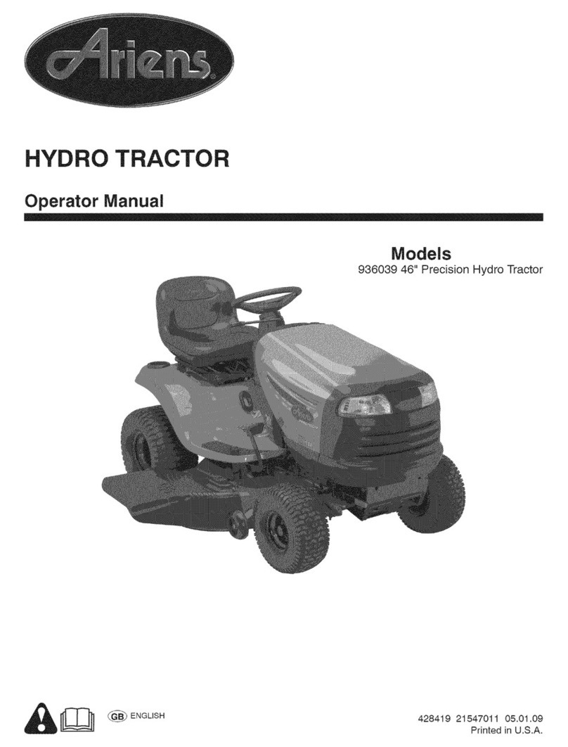
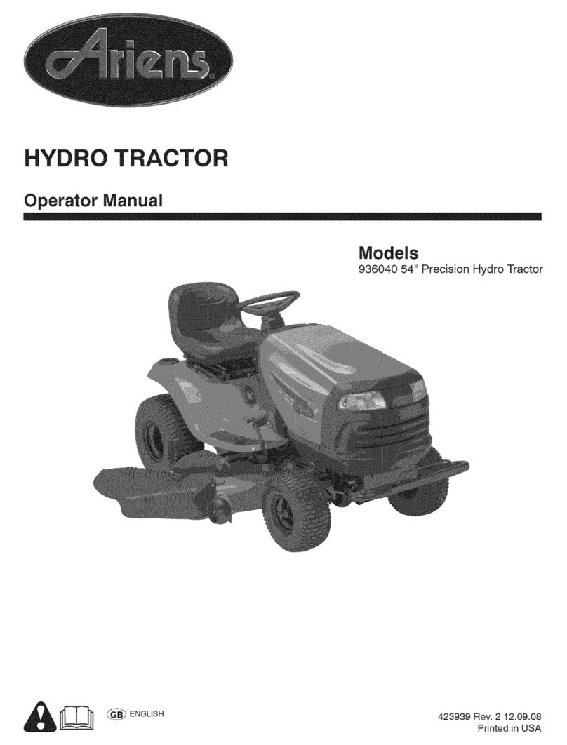
Ariens 936040 54" Precision Hydro Tractor User manual

Ariens

Ariens 936040 54" Precision Hydro Tractor User manual

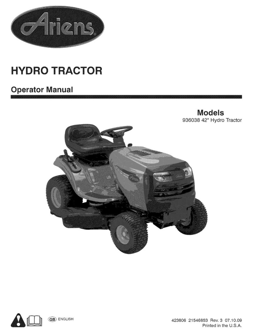
Ariens 936038 42" Hydro Tractor User manual

Ariens

Ariens 936038 42" Hydro Tractor User manual

Ariens 936093 User manual

Ariens

Ariens 936093 User manual

Ariens A18KG42 Owner's manual

Ariens

Ariens A18KG42 Owner's manual

Ariens 936045 42" Hydro Tractor User manual

Ariens

Ariens 936045 42" Hydro Tractor User manual

Ariens 936046 User manual

Ariens

Ariens 936046 User manual

Ariens 936039 46" Precision Hydro Tractor User manual

Ariens

Ariens 936039 46" Precision Hydro Tractor User manual

Ariens 935 Series User manual

Ariens

Ariens 935 Series User manual

Ariens 936083 User manual

Ariens

Ariens 936083 User manual

Ariens 42" Precision Gear Tractor User manual

Ariens

Ariens 42" Precision Gear Tractor User manual

Ariens 936037 42" Gear Tractor User manual

Ariens

Ariens 936037 42" Gear Tractor User manual

Ariens 931033 User manual

Ariens

Ariens 931033 User manual

Ariens 936085 User manual

Ariens

Ariens 936085 User manual

Ariens 936084 User manual

Ariens

Ariens 936084 User manual

Ariens A19A42 User manual

Ariens

Ariens A19A42 User manual

Ariens A20VA46 User manual

Ariens

Ariens A20VA46 User manual

Ariens 936085 User manual

Ariens

Ariens 936085 User manual

Ariens 936034 - 1540 Owner's manual

Ariens

Ariens 936034 - 1540 Owner's manual

Ariens A21A42 User manual

Ariens

Ariens A21A42 User manual

Ariens 936053 User manual

Ariens

Ariens 936053 User manual

Ariens 935269 42" Gear Tractor User manual

Ariens

Ariens 935269 42" Gear Tractor User manual

Ariens 931015 S-18 User manual

Ariens

Ariens 931015 S-18 User manual

Ariens 936041 42" Hydro Tractor User manual

Ariens

Ariens 936041 42" Hydro Tractor User manual

Popular Tractor manuals by other brands

Case HI STEIGER Series Service bulletin

Case HI

Case HI STEIGER Series Service bulletin

Case FARMALL 80N Tier 4A Service manual

Case

Case FARMALL 80N Tier 4A Service manual

Zetor UTILIX CL Operator's manual

Zetor

Zetor UTILIX CL Operator's manual

Zetor PROXIMA PLUS 8541 Operator's manual

Zetor

Zetor PROXIMA PLUS 8541 Operator's manual

Case IH JX Series Service manual

Case IH

Case IH JX Series Service manual

New Holland T9.390 Operator's manual

New Holland

New Holland T9.390 Operator's manual

Poulan Pro DB24H42YT Illustrated parts list

Poulan Pro

Poulan Pro DB24H42YT Illustrated parts list

Mahindra 35 Series Service manual

Mahindra

Mahindra 35 Series Service manual

Cub Cadet 2166 Operator's manual

Cub Cadet

Cub Cadet 2166 Operator's manual

Tektite Toro GM3280 ROPS Cab Operation manual

Tektite

Tektite Toro GM3280 ROPS Cab Operation manual

MacDon M150 2009 Setup Instruction

MacDon

MacDon M150 2009 Setup Instruction

Case IH MAXXUM 115 Service manual

Case IH

Case IH MAXXUM 115 Service manual

Kalmar TL2 Maintenance manual

Kalmar

Kalmar TL2 Maintenance manual

Raven AutoBoom installation manual

Raven

Raven AutoBoom installation manual

McCulloch M24-54T Operator's manual

McCulloch

McCulloch M24-54T Operator's manual

Charles RT115 Tier 3 owner's manual

Charles

Charles RT115 Tier 3 owner's manual

Kubota WSM L4400 Workshop manual

Kubota

Kubota WSM L4400 Workshop manual

Toro 13AX60RG544 Operator's manual

Toro

Toro 13AX60RG544 Operator's manual

manuals.online logo
manuals.online logoBrands
  • About & Mission
  • Contact us
  • Privacy Policy
  • Terms and Conditions

Copyright 2025 Manuals.Online. All Rights Reserved.